Table of Contents
Advertisement
Quick Links
Advertisement
Table of Contents

Related Manuals for Deye AE-FS2.0-2H2


Summary of Contents for Deye AE-FS2.0-2H2
- Page 1 Balcony Energy Storage System User Manual AE-FS2.0-2H2 Version:V1.1...
-
Page 2: Table Of Contents
Contents 1. Product Introduction ....................... 2 2. Parameters and Specifications ....................2 3. Packing List ..........................3 4. Safety Precautions ........................4 4.1 Preparations before Connecting ..................4 4.2 Safety Precautions during Use ..................4 5. Quick Guide ..........................5 5.1 Product Appearance ......................5 5.2 Introduction to Display Screen Icons ................ -
Page 3: Product Introduction
1. Product Introduction The DEYE1000/1000W Balcony Energy Storage System features built-in lithium iron phosphate battery cells and various functions including AC grid-connected charging/ discharging, off-grid power supply (UPS) applications, direct digital devices charging via USB ports, 2200W PV power charging, and battery capacity expansion up to 10kWh. Real-time monitoring of the power status is possible either locally via a touch screen, or remotely via an app. -
Page 4: Packing List
3. Packing List PV connector removal tool *2 GRID connecting wire 1.5m*1 PV positive connector *2 CT current transformer with PV negative connector *2 lead wire 5m*1 - 3 -... -
Page 5: Safety Precautions
4. Safety Precautions Reminder It is crucial and necessary to carefully read the User Manual (provided in the Appendix) before installing or using the battery. Failure to do so, not following any instructions or ignoring any warnings in this document may result in electric shock, serious injury, or damage to the battery, rendering the product non-functional. -
Page 6: Quick Guide
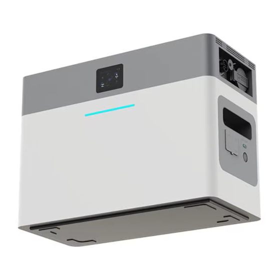
5. Quick Guide 5.1 Product Appearance ① CT interface ② Grid Interface ③ LOAD Interface ④ Main switch of AC output ⑤ USB-A output port *2 USB-C output port *2 ⑥ ⑦ USB output power switch ⑧ Main power switch ①... -
Page 7: Introduction To Display Screen Icons
5.2 Introduction to Display Screen Icons 5.3 Application Scenarios The battery offers solutions for both household energy storage systems and portable outdoor power supplies. The household energy storage systems can either come with PV charging or without it. For the system with PV charging, the UPS port is connected to the grid, and the PV port is connected to the PV power source. -
Page 8: Instructions For Connections Of The Product
6. Instructions for Connections of the Product 6.1 LOAD port First, make sure that the battery is turned off. Use a screwdriver to unscrew the lord interface protection cover as shown below. Open the protective cover of the lord interface, insert the plug of the appliance to be used into the interface, make sure the connection is tight. -
Page 9: Pv Port For Dc Input
The min. open-circuit voltage (Voc) of the PV module should be higher than 25V (min. Startup voltage of the inverter). Input voltage range: 20V - 60V. Inverter model AE-FS2.0-2H2 PV Input Voltage 25V (25V-60V) PV Array MPPT Voltage Range 20V-55V No. -
Page 10: Grid Port For Ac Input
Removal of the Connector's locking nut Use a crimping tool to crimp the metal terminal. Crimping the Terminal onto the Wire Insert the crimped terminal through the locking nut into the top of the connector, then tighten the locking nut back onto the connector. Connector (with the locking nut already tightened) Finally, insert the DC connectors into the positive/ negative input ends of the inverter. - Page 11 Model Area of the Circuit Breaker Maximum Cable Length Cable External cable AE-FS2.0-2H2 1.5mm 20A/400V (L+N+PE)20m Cable Information The AC output connector is divided into three parts: a socket, a sleeve, a sealing ring, and a locking nut. The connection steps are as follows: Step 1: Remove the sealing ring and the sleeve from the AC connector in turn.
-
Page 12: Ct Port For Dc Input
The orientation of the conductos for the AC Connector Step 6: Slide the sealing ring and the sleeve along the conductors until the sleeve clicks into the socket. Make sure the sealing ring is tightly fit into the sleeve around the conductors and then tighten the locking bolt. -
Page 13: Bat Port For Dc Input
connected to the grid supply represents the L phase, the blue wire represents the neutral N phase, and the green-yellow wire represents the ground wire (PE). We recommend installing an AC switch between the inverter AC input port and the grid supply. The specifications of the AC switch should be determined based on the load capacity. -
Page 14: System Diagram
shut down. If water enters the USB port, use a dry tissue to absorb the water. After drying it, the device can be used normally. Failure to do so may cause it to malfucntion but will not damage the USB port. -
Page 15: System Working Mode
6.8 System Working Mode Grid-connected mode: After the grid port is connected, the battery module and the connected PV power source can supply energy to the grid. The energy transfer logic can be configured, and it is also possible to set the grid supply and the connected PV power source to charge the battery module. - Page 16 power switches are not turned on and there is no load connected, the battery will automatically shut down after 5 minutes. The standby time can be set in the APP. - 15 -...
-
Page 17: Using The App
7. Using the APP You can control and monitor the battery through the Deyecloud APP or the website www.deyecloud.com. Download the Deyecloud APP by scanning the QR code below. 7.1 Login On the login page, you can choose to log in with email, phone number, or username. Enter the corresponding account information and click "Login". -
Page 18: Create A Plant
7.2 Create A Plant Step 1: Click on the top right corner of the plant page and select [Create A Plant]. Step 2: After filling in the relevant information about the plant, click [Confirm]. Note: Please select the correct grid connection type. For string inverters and micro-inverters, select the grid connection system;... -
Page 19: Configuration Of The Network
7.4 Configuration of the Network After successfully adding the collector, please configure the Wi-Fi network for the collector to ensure the system operates correctly. Method I: Network Configuration via Bluetooth Step 1: Go to the configuration page for network configuration. There are two ways to access the configuration page: ①... - Page 20 Step 2: Access the Bluetooth search interface by default. From the list of discovered devices, select the required SN. Step 3: The system will automatically retrieve the current network connected to the phone. You can also manually modify it. After entering the Wi-Fi password, click on [Next]. Step 4: After the network configuration is completed, you can enter a personalized name.
- Page 21 Method 2: Network Configuration via Wi-Fi For devices that do not support network configuration via Bluetooth, the network configuration can be done by scanning the QR code or entering the collector SN. Step 1: Click [Scan to Add] or [Manually Add] to add the device. Step 2: The system will automatically retrieve the current network connected to the phone.
- Page 22 Step 4: click [Connect] to skip to the WLAN page and configure the collector. Step 5: Select WLAN (AP+SN) prompted by the system and enter the password. Step 6: Click [←] to return to the APP after the successful connection. - 21 -...
- Page 23 Step 7: Connect the device and wait for the configuration process, including Configuring, Restarting, and Completing Verification. Step 8: After the "Configuration Succeeded" page is displayed, click [Complete] to close the page and complete the network configuration. - 22 -...
- Page 24 - 23 -...
-
Page 25: Use Of The Extender Battery Module
8. Use of the Extender Battery Module The extender battery module is used in conjunction with the AE-FS2.0-2H2 Balcony Energy Storage System. Up to four extender battery modules can be connected to the system, enabling a capacity expansion by up to 8kWh to meet the user's demand for a larger battery capacity. - Page 26 4. When connecting the extender modules, ensure that the connecting cables between the extender modules and the AE-FS2.0-2H2 battery system is inserted tightly. Failure to secure the connecting cables may result in overheating of the connection joints, affecting the system's performance.
-
Page 27: Faq
9. FAQ Q1: What type of battery is used for the product? Is the battery safe? The high-quality lithium iron phosphate battery is used for the product. The battery can operate safely and normally as the system is developed with multiple protection strategies which protect against scenarios of undervoltage, overvoltage, overcurrent, low tempreature, and high tempreature. -
Page 28: Common Faults And Troubleshooting Methods
10. Common Faults and Troubleshooting Methods Definitions and Solutions of Faults of the Balcony Energy Storage System Fault Code Definitions Solutions DC_Inversed Failure DC_Insulation_Failure GFDI_Failure GFDI_Ground_Failure EEPROM_Read_Failure EEPROM_Write_Failure DC/DC_Softstart_Fault GFDI_Relay_Failure IGBT_Failure AuxPowerBoard_Failure AC_MainContactor_Failure AC_SlaveContactor_Failure GFCI_Failure Active_Battery_Hold Tz_Integ_Fault Tz_GFDI_OC_Fault Tz_GFCI_OC_Fault Rreserved BusUnba lance_Fault DCIOver_M1_Fault Pa rallel_Comm_Fault... - Page 29 1. Once the issue is identified as per the 1. Check if the Deye inverter operating mode is set to lithium battery analysis method, proceed with the mode. corresponding solution.
- Page 30 Problem Description Analysis Method Measures 1. Check whether the charging and discharging MOS is functioning 1. Replace BMS; properly Battery pack Overvoltage protection 2. Check the ambient temperature of the battery pack. 2. Replace the battery pack. 3. Check if the battery pack is too old or damaged. 1.
- Page 31 Problem Description Analysis Method Measures 1. Check if the DI DO connections are correct. 1. Adjust the connected wiring harness. Host address duplication 2. Restart the master first and then restart the slave 1. Check whether the heating MOS is stuck or if it has trouble switching 1.
-
Page 32: After-Sales Service
During the warranty period, if damage is caused by manufacturing processes, materials, or other non-human factors, Deye ESS will provide free repair services and replacement of parts. The following conditions are not covered by the warranty: Unauthorized disassembly for maintenance or any other purposes;...
Need help?
Do you have a question about the AE-FS2.0-2H2 and is the answer not in the manual?
Questions and answers