Table of Contents
Advertisement
Quick Links
Advertisement
Table of Contents

Related Manuals for Deye Spring SE-G5.1 Pro-B


Summary of Contents for Deye Spring SE-G5.1 Pro-B
- Page 1 User Manual Spring series LFP Battery SE-G5.1 Pro-B Version:V2.2 ~ 1 ~...
- Page 2 Read and follow these instructions! The following precautions are intended to ensure your safety and prevent property damage. Before installing this product, be sure to read all safety instructions in this document for proper installation. Failure to comply with the instructions with this symbol may result in a serious accident, causing death or a severe injury.
-
Page 3: General Safety Precautions
1. Precautions 1.1 General Safety Precautions The product provides a safe source of electrical energy when operated as intended and as designed. Potentially hazardous circumstances such as excessive heat or electrolyte mist may occur under improper operating conditions, damage, misuse and/or abuse. The following safety precautions and the warning messages described in this part must be observed. -
Page 4: Product Introduction
Verify polarity at all connections before energizing the system. Reverse polarity at the battery terminals will void the Warranty and destroy the batteries. Do not short circuit the batteries. Do not combine Lithium Batteries with other brands or chemistries; Do not mix Lithium Batteries from different installations, clients, or job sites. -
Page 5: Product Specifications
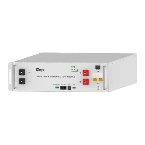
14. Used for fixing with cabinet. 15. Negative output terminal. 16. RUN light: green LED lighting to show the battery running status Alarm light: yellow and red LED lighting to show the battery has been alarmed or protected. 17. SOC: These 5 LEDs are used to display the pack SOC. The lightning of these LEDs indicates the SOC of 20%, 40%, 60%,80% and 100%. - Page 6 Storage Temperature 0℃~35℃ Humidity 5%~95% ≤2000m Altitude ≥6000(25°C±2°C,0.5C/0.5C,90%DOD,70%EOL) Cycle Life Wall-Mounted, Floor-Mounted, Rack-Mounted (19-inch standard Installation cabinet, cabinet depth ≥600mm Communication Port CAN2.0, RS485 UN38.3, IEC62619, CE,UKCA, VDE2510-50, FCC, UL1973, UL9540A, Certification REACH, ROHS [1] DC Usable Energy, test conditions: 90% DOD, 0.5C charge & discharge at 25°C. System usable energy may vary due to system configuration parameters.
- Page 7 3.1 Parts List Check the parts during unpacking. Table 3-1: Parts Lists Items Appearance Usage Qty. Remarks Battery Provide power Pair of 150mm 4AWG Battery power cable(both ends have 3U-LBCable150 waterproof terminals) and one 250mm RJ45 communication cable for battery parallel. Pair of 4AWG DC power cable (one end has a waterproof terminal, the other end is M10...
-
Page 8: Battery Installation
Table 3-2: Recommended Tools and Instruments Items Usage Appearance To fasten battery and Phillips Screwdriver or Bit assemblies Box Cutter Opening boxes Insulated Torque Wrench Installing cables and busbars Insulated Sockets Installing cables and busbars Measure battery module’s Battery Tester voltage 3.2 Visual Inspection of the Modules After transporting the modules to the installation location, check for:... -
Page 9: Battery Module Installation
Arc Flash and Shock Hazard Insulated tools are required for any work on this energized equipment. Sharp Edges Wear gloves and other protective gear to prevent injury. Pinch Point Use caution when working in the enclosure to prevent injury. Heavy Object Can cause muscle strain or back injury. - Page 10 Installation method 2:With standard 19 inches cabinet or rack installation The battery can be mounted on a standard 19 inches cabinet or rack. Battery modules can be inserted into a rack frame according to the customer battery configuration scheme. Installation method 3: Wall-mounted method The installation location description should meet the size requirements of the figure below: Figure 4-1...
- Page 11 Use the 6 screws of M4*8 to fix the battery pack Fixed Ears the both sides battery, as show in Figure 4-2. Figure 4-2 g) Choose the recommend drill head (as shown in Figure 4-3) to drill 4 holes on the wall,100mm-110mm deep.
- Page 12 Figure 4-4 The battery can be mounted on a standard 19 inches cabinet or rack. Battery modules can be inserted into a rack frame according to the customer battery configuration scheme. Note the allowable installation modes. ~ 12 ~...
-
Page 13: Cable Connection
5. Cable Connection 5.1 Single Battery Connection Before connect the cable with the inverter, the worker must confirm the output switch of the inverter has been turn off, to prevent the risk of fire or electric shock. Before connection, make sure to close the battery. ... - Page 14 Figure 5-1: Install the Grounding Wire Step 1 Wear the protective gloves. Step 2 Install the battery ground cable. Step 3 Install negative and positive power cables for the battery. 1) Remove the protective cover from the battery power wiring terminal. 2) Connect the negative power cable to the battery.
- Page 15 3) Take-down negative fixing bolt by the Phillips Screwdriver and connect the negative output cable between the battery negative terminal of the battery and the inverter. After connecting the battery, fastening bolt immediately to avoid dropping. 4) Install the protecting cover. 5) Sort the cables and fasten the battery cables to the perforated bracket with cable ties.
- Page 16 Max. 12kW Total Max. 240A DC+ BUS DC- BUS The first battery Each cable Max.120A If the inverter power exceeds 12kW, the parallel mode must be used mode 2! 2. Parallel mode2 (It is suitable for scenarios where the inverter power>12kW) Schematic diagram of parallel connection of high-power system batteries: Max.
- Page 17 Or larger capacity systems: Hybrid Inverter Battery Input Max.16pcs DC+ BUS DC- BUS OUT Port IN Port(Next Battery) The First Battery IN Port IN Port OUT Port Cluster 8 Cluster 1 Cluster 2 5.2.2. As shown in 5.2.1, connect the communication line (a standard RJ45 network cable) between the adjacent batteries.
-
Page 18: Activate The Product
(2) IN Port Definition (3) OUT Port Definition 5.3 Visual Inspection of the Connection After connecting the battery, check for: Usage of positive and negative cables. Connection of the positive and negative terminals. All the bolts are tightened. ... -
Page 19: Inspection, Cleaning And Maintenance
Start the Battery: After installation, wiring, and configuration are completed, you must check all the connection. When the connections are correctly, and then press power button to activate the battery. The green working light on of the battery flashes, indicating that the battery system is normal. -
Page 20: Troubleshooting
7.4 Maintenance The Li-Ion battery is maintenance free. Charge the battery to approximately > 80% of its capacity at least once every year to preserve the battery’s capacity. 7.5 Storage The battery product should be stored in a dry, cool, and cool environment; ... - Page 21 internal resistance of some cells rectify the fault. is too high. The mains power failure has lasted for a long time. The battery voltage is Cells are not consistent. The Under voltage less than 40V. capacity of some cells Same as above. protection The minimum cell voltage deteriorates too fast or the...
-
Page 22: Transportation Requirements
9.2 Recovery of anode materials The recovery process of anode materials is relatively simple. After the separation of anode plates, the purity of copper can be more than 99%, which can be used for further refining electrolytic copper. 9.3 Recovery of diaphragm The diaphragm material is mainly harmless, and has no recycling value. -
Page 23: Eu Declaration Of Conformity
Product: Rechargeable Li-ion Battery System Models: SE-G5.1Pro-B Name and address of the manufacturer: NINGBO DEYE ESS TECHNOLOGY CO., LTD No. 18,Zhenlong 2 Road,Binhai Economic Development Zone,Cixi,Ningbo,Zhejiang,China This declaration of conformity is issued under the sole responsibility of the manufacturer. Also this product is under manufacturer’s warranty.
Need help?
Do you have a question about the Spring SE-G5.1 Pro-B and is the answer not in the manual?
Questions and answers