
Related Manuals for Deye GE-F60


Summary of Contents for Deye GE-F60
- Page 1 Installation and Operation Installations High Voltage Battery GE-F60 Version: V1.0...
-
Page 2: Table Of Contents
Table of contents All Rights Reserved: ....................4 About This Manual ....................4 1 Safety Precautions ....................5 1.1 Personal Requirements ................... 5 1.2 Electrical Safety ....................6 1.3 Battery Safety ....................7 1.4 Hoisting and Transportation ................7 1.5 Installation and Wiring ..................7 1.6 Operation and Maintenance ................ - Page 3 4.5.3 Hoisting ........................27 4.6 Fixing Methods ....................27 5. Electrical connection ................... 28 5.1 Electrical connection Overview ..............29 5.2 Preparation before connection ............... 29 5.4 Cable connection ................... 30 5.4.1 Cable connections inside BESS ................30 5.4.3 Cable connection between BESS ................32 5.4.2 Cable connection between the inverter and BESS ..........
- Page 4 12.1 System Parameter ..................50 12.2 Contact Information..................51...
-
Page 5: All Rights Reserved
Software Licenses • It is prohibited to use data contained in firmware or software developed by Deye ESS, in part or in full, for commercial purposes by any means. • It is prohibited to perform reverse engineering, cracking, or any other operations that compromise the original program design of the software developed by Deye ESS. -
Page 6: Safety Precautions
Warning! Failure to follow the instructions of this sign may result in a serious accident resulting in serious personal injury. Caution! Failure to follow the instructions of this sign may result in minor or moderate injury. Notice! Provide information that is considered important but not relevant to the danger. -
Page 7: Electrical Safety
1.2 Electrical Safety Danger! • Touching the power grid or the contact points and terminals in the devices connected to the power grid may lead to electric shock! All circuit connectors must be disconnected during maintenance. • The battery side or the power grid side may generate voltage. Always use a standard voltmeter to ensure that there is no voltage before touching. -
Page 8: Battery Safety
• Do not store batteries with inflammable and explosive materials. This may cause product damage or property loss. Maintain the battery according to this manual. Deye ESS is not responsible for insurance and claims if maintenance is not performed in accordance with this manual. -
Page 9: Disposal Of Waste
GE-F60 lithium iron phosphate battery the new energy storage products developed and produced by DEYE ESS, which can be used to support the reliable power supply of various equipment and systems. The GE-F60 is particularly suitable for high-rate cyclic charging and discharging scenarios. -
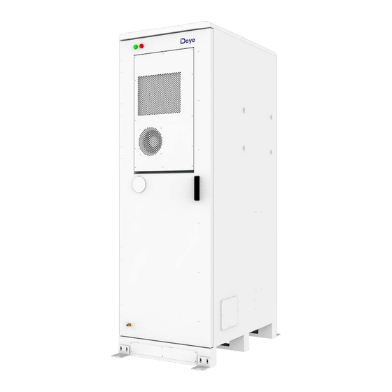
Page 10: External Design
2.2 External Design Cabinet Appearance ⑤Flammable gas outlet: When flammable gas ① Indicator light: When the green light comes on, the BESS is Run. When the red appears in the BESS, it can be discharged light comes on, the BESS gives an alarm. through this outlet. -
Page 11: Air-Conditioner Design
2.3 Air-conditioner Design System built-in air conditioner cooling The air conditioning system uses steam compression refrigeration, so that it becomes cold air, and then sends it to the internal air duct of the energy storage cabinet to cool the battery. Energy storage Air Conditioning Model:... -
Page 12: Internal Design
2.4 Internal Design 2.4.1 Internal Equipment ①Air conditioner Cooling the BESS. When the BESS is detected to be on fire, aerosol ②Aerosol Fire Suppression Device is emitted to extinguish the fire. ③Travel switch Check whether the BESS’s door is closed. A device used to detect smoke in a fire and sound ④Smoke detector an alarm when smoke is detected. - Page 13 ①Fan Emission of combustible gas Detect combustible gases and notify ②Combustible gas sensor aerosol fire suppression systems ③Serial relay Control system ④Terminal line For connecting cables ⑤Switching Mode Power Supply Power source Used to measure ambient temperature ⑥Temperature and humidity sensor and humidity...
-
Page 14: Battery Introduction
⑦Miniature circuit breaker Controlled power-on and power-off Automatic regulation, safety protection, ⑧Lightning protection backup protector conversion circuit ⑨Water immersion sensor Check the BESS for water leakage ⑩Terminal line Connect external cables 2.4.2 Battery Introduction Battery Module Battery Type LiFePO4(LFP) Nominal Voltage 51.2Vdc Rated Capacity 100Ah... - Page 15 Detection of aerosol concentrations in the ①Aerosol sensor Provides electrical energy storage and ②Battery module output ③CCS Cells Contact System ④Vent hole Heat dissipation ⑤Battery Negative- ⑥Battery Positive+ ⑦Fan Promote internal and external air flow ⑧BMU Battery monitoring Power Distribution Unit...
- Page 16 Operating Voltage 120~750Vdc Nominal Charge/Discharge Current 100A Max. Charge/Discharge Current 125A DC Input Rating 12±2%V/4.15A Operating Temperature Range -20~65°C Ingress Protection IP20 Dimension (W/D/H) 440*570*150mm Weight Approximate 17kg Connection position of the common negative pole of the ①B- battery Connection position of the common positive pole of the battery ②B+ Used to manually control the connection between the battery ③Air switch...
-
Page 17: Indicator Light Design
2.4.3 Indicator light Design Indicator light: When the green light comes on, the BESS is Run. When the red light comes on, the BESS gives an alarm. 1. The following faults trigger either level 2 fault. The cabinet ALARM red light is on, the external ALARM light is on, and the RUN indicator is off. - Page 18 Charging low Main positive relay 40 Pre-charge failed fault temperature fault adhesion Discharging low The Charging voltage is too blown fuse temperature fault Pressure difference BMU repeat fault 42 BMU communication fault too large fault Temperature difference too large BMU repeat fault 43 BMU number anomaly fault Internal CAN...
- Page 19 humidity 1 fault communication fault 4 Low humidity alarm 12 Internal ambient 20 Internal fan overloaded humidity 2 fault fault 5 Electric heating 13 Inner coil temperature 21 External fan failure protection fault 6 Outdoor ambient 14 Pressure sensor failure 22 External fan temperature fault communication fault...
-
Page 20: Transport And Storage
too large fault Temperature difference too large BMU repeat fault 43 BMU number anomaly fault Internal CAN Abnormal Mot total High SOC fault communication fails pressure collection Abnormal Temperature Cell temperature low PCS CAN collection of the BMS voltage fault Communication fails connector Abnormal Temperature... -
Page 21: Storage Requirement
Additional traction may be required if ESS needs to be transported on slopes. Remove all obstacles that exist or may exist on the way, such as tree branches, cables, etc. The BESS should be transported and moved under good weather conditions. ... -
Page 22: Mechanical Installation
Notice! : To ensure battery life, keep the storage temperature of the battery module between 0 ° C and 35 ° C • Storage If the battery energy storage system is not used for a long time, please refer to the following table to save power. -
Page 23: Product Inspection
4.1.2 Product Inspection Check BESS and internal equipment for damage. If you find any problems or have any questions, please contact the agency or Deye ESS. 4.2 Installation Environment • The environment around the installation site should be dry and well-ventilated. -
Page 24: Installation Spacing Requirement
Foundation laying drawing(Unit: mm) Notice! : The dregs excavated during the foundation construction should be removed immediately to avoid affecting the hoisting in the later stage. 4.3 Installation Spacing Requirement Installation spacing drawing(Unit: mm)... -
Page 25: Installation Of Inverters And Bess
4.4 Installation of inverters and BESS First remove the M12 screws on the BESS with the wrench of the M12 and install the inverter rack on the BESS. Second fix the inverter on the rack, and drive three screws on each side with a phillips screwdriver to complete the installation. -
Page 26: Transportation And Lifting
4.5 Transportation and lifting 4.5.1 Transportation Forklift Transport If the installation site is flat, use a forklift to move the equipment. The bottom of the machine has a special forklift transport fork hole. A forklift with a rated load of more than 1500kg should be used. -
Page 27: Hoisting Equipment
4.5.2 Hoisting Equipment Warning! : Comply with crane safety procedures at all times. Do not stand within 500-1000mm of the lifting area! During the whole lifting process, no one is allowed to stand under the boom or the work station. The lifting work must be stopped in bad weather. -
Page 28: Hoisting
4.5.3 Hoisting In the process of lifting the devices, each operation link should be carried out according to the following requirements: • The equipment should be hoisted vertically and should not be dragged on any surface during hoisting. • Check the connection between the lifting tool and the device before hoisting. •... -
Page 29: Electrical Connection
Fix the L-shaped Angle steel to the cabinet first, and then drive the expansion screws to fix the ground. Use screws (M10*30) with torque (30N·m) above and use expansion screw(M12*80) to fix the bolt angle. Due to the uncertainty of drilling accuracy and bit material, it is recommended to choose a drill bit from φ16.5 to φ17. -
Page 30: Electrical Connection Overview
Warning! Sand and moisture infiltration can damage the electrical equipment in the container or affect its operating performance! Do not perform electrical connections during sandstorms or when the relative humidity of the surrounding environment is greater than 95%. Make electrical connections when there is no wind or sand and when the weather is clear and dry. -
Page 31: Cable Connection
Goggles Safety shoes Safety gloves Protective tools Protective clothing Opening mode Opening procedure 1. Locked State 2. Move the cover above the keyhole upward 3. Insert the door key and turn it clockwise to eject the handle 4. Turn the handle clockwise to the position shown in the picture to open the front door. 5.4 Cable connection 5.4.1 Cable connections inside BESS Power cable connection: The 215mm power cord of battery module is used to connect the... -
Page 33: Cable Connection Between Bess
5.4.3 Cable connection between BESS It can be connected to one to six BESS. It is recommended that each BESS be connected to power distribution separately. If the power distribution is not connected separately, follow the method recommended by Deye ESS. -
Page 35: Cable Connection Between The Inverter And Bess
5.4.2 Cable connection between the inverter and BESS 1. If the BESS is connected in parallel, open the cabinet door and connect according to the following figure. The negative copper bar is connected to the PDU P- and the negative electrode of the inverter. -
Page 36: Operation After Cable Connection
5.5 Operation after cable connection When all electrical connections are complete, check the wiring thoroughly and carefully. In addition, you need to do the following: • Check all air intakes and outlets for blockage. • Seal the gap around the cable inlet hole. Warning! •... -
Page 37: Power-On Procedure
• Check whether the emergency stop button is released. • Check and confirm that there is no ground fault. • Use a multimeter to check whether the AC voltage and DC voltage meet the starting conditions and ensure that there is no overvoltage. •... -
Page 38: Unplanned (Emergency) Shut Down
6.3 Unplanned (emergency) shut down Fire incidents: Contact your local fire professional. Unplanned downtime (downtime due to failure) : Contact Deye ESS. 7 Fire Suppression system Caution! The battery is equipped with fire suppression equipment General rules: Please comply with the fire laws and regulations of the country/region where the project is located. -
Page 39: Exhaust System
7.2 Exhaust system When the ① combustible gas detector detects flammable gas in the housing, the ② fan will open and exhaust the flammable gas. -
Page 40: Troubleshooting
8 Troubleshooting To determine the status of the battery system, users must use additional battery status monitoring software to examine the protection mode. Refer to the installation manual about using the monitoring software. Once the user knows the protection mode, refer to the following sections for solutions. -
Page 41: Inspection, Cleaning And Maintenance
9. Inspection, cleaning and maintenance. 9.1 Basic Information The battery is not fully charged. It is recommended to complete the installation within 3 months after the arrival of goods. Do not disassemble any battery in the battery product, do not dissect the battery; ... - Page 42 Check whether there are foreign objects, dust, dirt, and condensed Inside the BESS water inside the BESS. Check the temperature of the radiator and the amount of dust Air inlet and outlet accumulated. Clean heat-dissipation modules with a vacuum cleaner if necessary Completely power off the devices inside the ESS before checking.
-
Page 43: Battery Maintenance
free of stains and damage. Replace them if necessary. Surge protection Check whether the SPD and fuse are properly fastened. device and fuse Corrosion Check whether there is oxidation or rust inside the container. 9.3 Battery Maintenance Below is the recommended maintenance cycle. The actual maintenance cycle should be adjusted according to the specific installation environment of this product. - Page 44 specifications. If case of any abnormality, take corrective actions immediately. • Check whether all wire inlets and outlets of the battery cluster are sealed properly. • Check the battery cluster for internal seepage of water. • Check whether the power cables and copper busbars are loose, and tighten them according to the aforesaid torque.
-
Page 45: Upgrade
If you have any questions about the operation and maintenance of this product, please contact Deye ESS customer Service center, do not operate without authorization. 10 Upgrade 10.1 USB Upgrade USB only supports USB flash drives with FAT32 file system format. - Page 46 Step 2. Click to start Step 3. If the system upgrade is successful, the lower right corner will prompt green success, and if it fails, it will prompt red failure.
- Page 47 2. Upgrade a single PACK Step 1. After successfully connecting to the host computer, select "Firmware - Browse - Upgrade File" Step 2.Select the upgrade pack number, if there is "0x" in "Device Address", enter the corresponding hexadecimal number, such as upgrading Pack No. 29, enter 1D; if there is no "0x" in "Device Address", enter the corresponding decimal number No., if you upgrade Pack No.
-
Page 48: Pcs Upgrade
Step 3. If the system upgrade is successful, the lower right corner will prompt green success, and if it fails, it will prompt red NG. 10.3 PCS Upgrade Step1. Open the website https://pv.inteless.com/plants, enter the account number and password. - Page 49 Step2.In the device list-inverter list, enter the collector serial number to find the target collector. Step3. Select the target device and click Remote Upgrade.
-
Page 50: Battery Recycling
Step4. Select "Energy Storage Machine/BMS" for the firmware type, select the firmware version provided by the technician, and click OK to start the upgrade. 11. Battery recycling When the equipment or internal equipment reaches the end of its service life, it cannot be disposed of together with domestic waste. -
Page 51: Recovery Of Anode Materials
The diaphragm material is mainly harmless, and has no recycling value. List of recycling equipment Automatic dismantling machine, pulverizes, wet gold pool, etc. 12 Contact Information 12.1 System Parameter Model GE-F60 System Specification Nominal Output Power/UPS Power (W) 50000 50/60Hz; 3L/N/PE 220/380, 230/400Vac AC Output Frequency and Voltage... - Page 52 12.2 Contact Information For more information on battery module handling, please contact us. Service hotline :+86 0574 8612 0560, Email :service-ess@deye.com.cn For more information, visit http://deyeess.com. Comply with the regulations on waste battery disposal. Stop using the damaged battery immediately. Contact your installer or sales partner before processing. Keep the battery away...
Need help?
Do you have a question about the GE-F60 and is the answer not in the manual?
Questions and answers
WHAT IS THE PRODUCT DESCRIPTION FOR GE-F60