Table of Contents
Advertisement
Quick Links
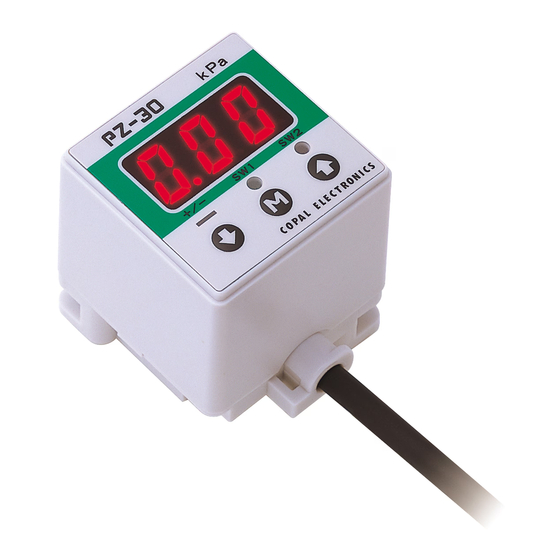
SMALL SIZE
PRESSURE INDICATOR
PZ-30
marking
(Compliance with EMC Standards)
Instruction Manual
Ver.5.0
These products (pressure sensors, pressure switches, pressure gauges, pressure indicators, leakage sensors,
etc.) are designed and manufactured as general industrial parts. Therefore, a person with sufficient knowledge
and experience shall confirm the conditions and environments described in the catalog, specifications, and
instruction manual of each product, check the suitability of the product for the machine, device, or system which you use,
and ensure safety before use.
These products are not intended to be used for applications particularly requiring high reliability (These include, but are
not limited to, nuclear power control, aerospace and military purposes).
The details of warranty shall be as per the descriptions in this document and we shall not be liable for any damage on you
resulting from the use of any equipment or device (including control systems) which is not in accordance with this
document (hereinafter referred to as "use in violation"). In the case where you resell our products, we shall not be liable
for any damage on a third party resulting from use in violation by the third party, and even if we make payment to the third
party in connection with such use in violation regardless of the name by which such payment may be called, we may
demand the whole amount thereof from you.
①This product is a pressure indicator which displays the detected pressure by connecting a pressure sensor with a
built-in amplifier and setting the rated pressure range of an applicable sensor. Since the product type differs
according to the specifications (voltage and current signals) of each sensor, use it with appropriate combinations.
②The power voltage applied to this product is used as the drive voltage for the sensor connected. Therefore, make sure
the power requirements of the sensor and use it within the allowable specification range.
③Make cable wiring when the power is turned OFF. Be careful to mis-wiring and non-wiring, it may damage the product.
④Use a stable DC power supply. For the relay, solenoid, or other inductive loads used on the same power circuit with
this product, use an appropriate surge absorption element (diode, varistor, etc.) ( Refer to the figure at right.)
⑤The protection structure of this product conforms to IP40 of IEC standards or equivalent. The product is not suitable
for use in dust- and drip-proof environments requiring higher standards. In
addition, since it does not have an explosion proof structure, do not use it
in flammable gases.
⑥Do not pull the cable with a force of 40N or more when handling this
product, as this may disconnect the cable or damage the product.
⑦Do not use pointed objects such as pens to press the setting buttons on
the display panel.
⑧Use pH neutral detergents to clean the housing of this product. Do not
use thinners or other solvents.
Important Information and Warnings
Thank you for purchasing a
NIDEC COMPONENTS
In order to use the product correctly and most appropriately,
please completely read this manual before use and keep it
for future reference.
For more detailed information please ask for the
nearest distributor or the following sales center.
Nishi-Shinjuku Prime Square bldg., 7-5-25
Nishi-Shinjuku, Shinjuku-ku,Tokyo 160-0023, Japan
Phone: +81-3-3364-7055 Fax: +81-3-3364-7098
URL : https://www.nidec-components.com
CORP. product.
Surge voltage
Unit power supply
absorption circuit
AC input
DC input
F G
Grounding of
FG terminal
+ V
kPa
+/-
SW1
SW2
1
Advertisement
Table of Contents

Related Manuals for Nidec PZ-30


Summary of Contents for Nidec PZ-30
- Page 1 (Compliance with EMC Standards) Nishi-Shinjuku Prime Square bldg., 7-5-25 Nishi-Shinjuku, Shinjuku-ku,Tokyo 160-0023, Japan Instruction Manual Phone: +81-3-3364-7055 Fax: +81-3-3364-7098 URL : https://www.nidec-components.com Ver.5.0 Important Information and Warnings These products (pressure sensors, pressure switches, pressure gauges, pressure indicators, leakage sensors, etc.) are designed and manufactured as general industrial parts. Therefore, a person with sufficient knowledge and experience shall confirm the conditions and environments described in the catalog, specifications, and ...
-
Page 2: Specifications
Specifications Sensor input signal 1〜5V type(V type)/ 4〜20mA(I type) Sensor connection ST: Terminal board type, Osada ONC-051(one-touch type) CN: Connector type, AMP 0-171826(pin-header type) Power voltage 10.8〜30VDC(including ripple) Current consumption 50mA or less Pressure display Full 3 digit LED display(sampling cycle: 4 times per second) Negative pressure display (±)Red LED is lit Display accuracy ±1%FS(not including sensor errors) Temperature characteristic ±0.5%FS(0-50℃, at 25℃ reference) Switch outputs 2 outputs, NPN/PNP transistor open collector Switch capacity 30VDC 100mA or less Residual voltage 1.2V or less(NPN)/ 2.2V or less(PNP) Hysteresis 0〜300counts(variable) Repeatability ±0.2%FS Short circuit protection Provided Response Approx.5ms(digital filter setup: F-0) Temperature ±0.5%FS(0-50℃, at 25℃ reference) Operation display Output 1 (green LED) and Output 2 (red LED) light up when outputs are ON. Analog output Voltage output of sensor input signal: 1〜5V Operating... -
Page 3: Operation Panel
Operation Panel 3 digit LED Pressure display unit (SW1) LED (SW2) LED (−) LED button button button Initial LED Display (About 3 Seconds) All LEDs flash twice. The Rated Pressure Setting The Operations Mode ( pressure code flashes. detection) is activated. Input/Output Circuit Diagrams (Wire Colors Conform to IEC Standards) 〈Voltage analog output〉 〈Current analog output〉... -
Page 4: Operating Procedure
Operating Procedure Operations Mode In the Operations Mode, press In the Operations Mode, press the the and buttons simultaneously and buttons simultaneously for more for more than one second. than one second. 〈Initial Settings Mode〉 〈Pressure Settings Mode〉 ①Magnification Setting ①Setting 1 (Voltage Output Setting) ②Setting 2 In each Settings Mode, press ②SW Output Setting ③Response ( Common) the button for more than ③Rated Pressure Setting one second. ④Filter Settings Initial Settings Mode/Setting Procedure (When changing the rated pressure, perform③Rated Pressure Setting first.) Press the and buttons Press the button to move Press the button for Use the and button to simultaneously to enter to the next digit. The value of set the value of each digit. more than one second the Initial Settings Mode. the digit may be set when the to return to the LED below the digit flashes. Operations Mode. Press the button to move Third ... - Page 5 In the Operations Mode, press the The ( −) LED flashes to notify the The ( −) , (SW1) , and ( SW2) LEDs In this example, "−12P": 0 to and buttons simultaneously Magnification Settings Mode. First, flash to notify the Rated Pressure −100kPa is selected and the for more than one second. enter the Rated Pressure Settings Settings Mode. The "12P" display LED flashes to indicate that it ...
- Page 6 Magnification Setting/Rated Pressure Setting Indication method Gauge / absolute pressure Mode ( 1/3) Pressure unit Magnification Setting Rated pressure range 0〜10 0〜35 0〜50 0〜-100 0〜100 0〜350 0〜500 0〜600 0〜700 0〜1000 0〜2.00 Code Magnification Setting code “11P” “41P” “51P” “-12P” “12P” “42P” “52P” “62P” “72P” “13P” “23P” 0.00 “1” ×1 (kPa) 9.99 35.0 50.0 -99.9 99.9...
-
Page 7: Digital Filter Setting
Pressure Settings Mode/Setting Procedure (Perform②SW Output Setting in the Initial Settings Mode first.) In the Operations Mode, ①The ( SW1) LED flashes to notify the In this example, Setting 1 is ②The ( SW2) LED fla-shes press the and Setting 1 Settings Mode. In this example, set to −700. Press the to ... - Page 8 Others 〈Non-Display Mode〉 ○Non-Display [ Temporary] Mode ・ When the keys are not operated for more than 10 seconds during Operation Mode,the system will automatically select Non-Display [ Temporary] Mode and the display will turn off. ・ Decimal point LED shown in the figure below will blink during Non-Display [ Temporary] Mode. ・ Using the EEPROM,the PZ-30 series can retain preset values even if the power is turned off. ・ If an error message is detected,the display will comeback and show the error message. ・ You can change any functions during Non-Display [ Temporary] Mode. ・ When you set Non-Display [ Full-time] during Non-Display [ Temporary] Mode. the mode change Non-Display [ Full-time] Mode. (How to set) Blink ・ To enable Non-Display [ Temporary] Mode,press key for more than 4 seconds. will be displayed and Non-Display [ Temporary] Mode will be ...
-
Page 9: Warranty And Disclaimer
〈Key Protection Mode〉 ○key protection Mode ・ Key Protection Mode is used to lock the front panel key in order to prevent preset values from being accidentally changed. ・ Using EEPROM,the PG-30/35 series can retain the preset values even if the power is turned off. (How to set) ・ To enable key Protection Mode,press key for more than 4 seconds. will be displayed and the keys will be locked. ・ To disable key Protection Mode,press key for more than 4 seconds. will be displayed and the keys will be unlocked. 〈Cousion of attachment〉 ○If mounting with an angled bracket, the maximum torque of the M3 screws should be less than 0.3N−m. ○If mounting with an Panel holder set, do not apply excessive force. Warranty and Disclaimer 1) The warranty period of these products is one year after delivery to a designated place. The warranty mentioned here is limited to the warranty of a delivered product itself, and it does not cover consumables such as batteries. Each product has its own specifications such as durability (pressure cycles). Therefore, check with each service office. 2) If a failure or damage of the product occurs during the warranty period, for which we are responsible, we will promptly replace or repair the product free of charge. The warranty mentioned here means the warranty of the product itself and does not cover any damage induced by a failure of the product. 3) The warranty does not cover when any of the following items is applicable: ・ The failure is caused by conditions, environments, or handling not described in the catalogue and agreed specifications and other documents. ・ The product has been modified, adjusted, or repaired by a person/company other than our company after delivery. ・ The failure cannot be foreseen by the scientific and technological knowledge at the time of delivery. ・ The failure is caused by force majeure such as disasters. - Page 10 Outline Dimensions (Unit:mm) Terminal board type □31.4 □30 2 ‒ M3 Depth 6 Window PZ-30 Push button 5 core cable +/‒ L = 2000 ± 100 AWG26 Wire input Terminal : OCN-051 manufactured by Osada Wire : AWG16〜26 Wire strip length : 9〜10mm Connector type □31.4 □30 1 2 3 Rear Terminal No. 2-M3 Depth 6 26.5 PZ-30 5 core cable 3 2 1 Connector Pin No. L = 2000 ± 100 AWG26 Connector : 0-171826-3 (Pitch 2.5) manufactured by AMP (Housing : 0-171822-3) Connector pin No. Rear terminal No. Connection of pressure sensor V+:Power supply voltage output (Input voltage) Sensor signal: Voltage output Vs (1〜5V) /Current output Is (4〜20mA) COMMON(※) When connecting the 2-wire type of current output sensors, please do not connect the 3 (Com.) terminal.
-
Page 11: Angled Brackets
50max. □42.6 24.7 6max. +0.5 〈Accessories(Sold separately)〉 Panel holder set Product name Model no. Description Angled bracket for Angled bracket for wall attachment Panel holder cover ACPG-011 wall attachment Two M3x4 male screws Panel holder Angled bracket for Angled bracket for floor attachment Main body ( PZ-30) ACPG-012 floor attachment Two M3x4 male screws Attachment Panel holder cover panel Panel holder Panel holder set ACPG-003 Two panel stoppers Holder cover set Panel holder cover Holder ACPG-004 (for protection of gauge sides) Panel holder cover set Panel holder Panel ...
Need help?
Do you have a question about the PZ-30 and is the answer not in the manual?
Questions and answers