Table of Contents
Advertisement
Quick Links
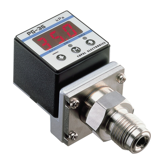
SMALL SIZE PRESSURE GAUGE
PG-35H
INSTRUCTION MANUAL
Important Information and Warnings
①For stability, use a regulated direct current power supply.
Surge absorbing devices(diodes, varistors, etc.)are necessary if inductive loads such as relays or
solenoids are connected to the same circuit as the PG-35H.
If using a DC power supply unit such as a switching power supply, the FG terminal should be earthed. Do
not wire in parallel to high tension cables or power lines, or use cable ducts which contain high tension
cables or power lines.
②Be careful not to crimp any wires during handling, or put any pressure on the display area of the main body
while assembling piping.
③Use pH neutral detergents to clean the body. Do not use solvents such as thinners.
④This product is dust proof and drip proof(IP65 of IEC standards)and is not suitable for use in
environments requiring higher standards.
Also, do not use this product in an environment with a possibility of product being covered by liquids other
then water(Such as oil, solvent, and etc.)and outdoor.
⑤Do not use pointed objects such as pens to press the setting buttons on the display panel, as this may push
holes in the setting buttons and damage them.
⑥Do not insert wires, etc. in the pressure port, as this may damage the internal diaphragm and cause
malfunctioning.
⑦The PG-35H series do not have an explosion proof structure.
Do not use it for the detection of flammable gases.
⑧When analog output is supplied to a noise-sensitive device,a
low-pass filter is requested in a customer's circuit.
⑨Countermeasures for noise interference:
Please connect either the shield wire or the metal part of the
product to frame ground(FG)of the power source.
⑩In case a wire extension is needed, please use a shielded
wire.
Thank you for purchasing a
NIDEC COPAL ELECTRONICS CORP. product.
In order to use the product correctly and most
appropriately, please completely read this manual before
use and keep it for future reference.
For more detailed information please ask for the nearest
Ver.3.2
distributor or the following sales center.
Nishi-Shinjuku Prime Square., 7-5-25
Nishi-Shinjuku, Shinjuku-ku, Tokyo 160-0023 Japan
https://www.nidec-copal-electronics.com
Power supply unit
AC input
Earthing of FG terminal
DC output
FG
Surge absorbing circuit
1
Advertisement
Table of Contents

Related Manuals for Nidec PG-35H Series


Summary of Contents for Nidec PG-35H Series
- Page 1 Thank you for purchasing a NIDEC COPAL ELECTRONICS CORP. product. In order to use the product correctly and most SMALL SIZE PRESSURE GAUGE appropriately, please completely read this manual before use and keep it for future reference. PG-35H For more detailed information please ask for the nearest distributor or the following sales center. Nishi-Shinjuku Prime Square., 7-5-25 INSTRUCTION MANUAL Nishi-Shinjuku, Shinjuku-ku, Tokyo 160-0023 Japan Ver.3.2 https://www.nidec-copal-electronics.com Important Information and Warnings ①For stability, use a regulated direct current power supply. Surge absorbing devices(diodes, varistors, etc.)are necessary if inductive loads such as relays or solenoids are connected to the same circuit as the PG-35H. If using a DC power supply unit such as a switching power supply, the FG terminal should be earthed. Do not wire in parallel to high tension cables or power lines, or use cable ducts which contain high tension ...
-
Page 2: Specifications
Specifications PG-35H Model 104R 354R Type Gauge pressure Rated pressure range −0.1〜10MPa −0.1〜35MPa Maximum pressure 20MPa 50MPa Break-down pressure 40MPa 50MPa Oil that do not corrode Fe and Ni Acceptable media Liquids or gases that do not corrode SUS316 10.8〜30VDC (including ripple) Operating voltage Current consumption 50 mA maximum Two outputs NPN/PNP:Transistor open collector Switch rating: 30VDC100mA maximum Residual voltage: 1.2V maximum (NPN) /2.2V maximum (PNP) at 100mA. Hysteresis 0〜300 counts setting ( adjustable) Switch Repeatability ±0.2%FS±1digit... -
Page 3: Function Names
Output Electrical Diagram (Wire colors correspond to IEC standards) Open Collector Output Model Open Collector Output Model (brown) (brown) Display Display Power supply Power supply D.C 10.8〜30V D.C 10.8〜30V (gray) (black) Switch output 1 load load Analog Wire color Connection output (white) Brown Power ⊕ (black) Switch output 2 Sensor Sensor Sensor Sensor Gray Analog output Switch output 1 (gray) load load (white) Analog Black SW output1 Switch output 2 output White... - Page 4 Multiplier factor Setting The multiplier factor setting is determined by the value of the third digit : the red −LED should be flashing during the setting. Pressure range ( −Pr〜+Pr) Muitiplier factor 104R 354R ×0.0102 −1.0〜99.9 −1〜357 ×0.01 −1.0〜99.9 −1〜350 ×145 −0.01〜1.45 −0.01〜5.07 ×0.001 −0.10〜9.99 −0.1〜35.0 Sections containing an oblique stroke are multiplier factor that cannot be selected because of resolving power or display digits. (Values will not be displayed automatically.) Note:“A” is set prior to delivery. An example of setting “2”. In the operations mode, press Press the button until Set the value of the third Press the button for more the and buttons simultaneously the − LED under the digit to “2” using and than one second to return to enter the Initial Settings Mode. third digit flashes. buttons. to the Operations Mode. ※Change of magnification setting is effective only for pressure reading. Set values for switching are not scaled automatically. Analog Output Setting The analog output setting is determined by the value of the second digit:the green SW1 LED should ...
- Page 5 Switch Output Setting The switch output setting is determined by the value of the first digit : the red SW2 LED should be flashing during the setting. Output SW1 output SW2 output There are four operation modes. These are shown in the diagrams below. Mode Separate Window comparator Separate Window comparator Separate Mode Window Comparator Mode Operation (H operation) (A operation) ○ ○ ○ ○ ○ ○ P1 : SW1 P2 : SW2 ○ ○ ○ ○ (L operation) (B operation) ○ ○ ○ ○ ○ ○...
-
Page 6: Hysteresis Setting
Pressure Settings Mode M P a M P a M P a M P a +/− +/− +/− +/− C O PA L E L E C T R O N I C S C O PA L E L E C T R O N I C S C O PA L E L E C T R O N I C S C O PA L E L E C T R O N I C S Set the value using the... -
Page 7: Troubleshooting
Troubleshooting ■If the following error messages are displayed, follow the procedures in the table. Display and problem Cause Solution Turn off the power and verify the load Output current is exceeding 100mA. connected switch output 1 and 2. Pressure was applied at the zero point Press M button and return the applied pressure to the adjustment. atmospheric pressure and try zero-point adjustment again. Please contact us. Please use a regulated DC power Failure of the internal circuit. E-3, E-4 supply and measures for the power line noise. 999Flashing Pressure values exceed the display range. Normal state Flashing of the Pressure values exceed the rated pressure Normal state pressure valie range. (110%FS) Black out of the Non-display mode Normal state ( See Non-display mode.) display Disable the key Key protection mode Normal state ( See Key protection mode.) operation Zero point Adjustment Pressing the and buttons simultaneously in the Operations Mode M P a displays on the screen. One second later this change to than ... - Page 8 M P a M P a M P a M P a Blink +/− +/− +/− +/− C O PA L E L E C T R O N I C S C O PA L E L E C T R O N I C S C O PA L E L E C T R O N I C S C O PA L E L E C T R O N I C S ・To enable Non-Display [...
- Page 9 Outline Dimensions(Unit:mm) ■PG-35H Outline Dimensions Fitting part:R2 type 31.4 □3 0 10.5 Five core shielded cable L=2000±100 COPAL ELECTRONICS 2 −M 4 Drpth5 R1/4;Fe,Ni Fitting part: G3 type 31.4 □3 0 10.5 Five core shielded cable L=2000±100 COPAL ELECTRONICS 2 −M 4 Depth5 G3/8;SUS316L...
- Page 10 Brackets(Option) ■PG-35H Holder cover set (sold separately) (5.7) □42.6 □40 24.7 Panel holder cover Panel holder Main body COPAL ELECTRONICS Holder cover set ■Accessories(Sold separately) Product name Model no. Description Appllcable model Holder cover set PG-30/35 Panel holder cover, (for protection of ACPG-004 PG-35H panel holder gauge sides) (Note) Since this product contains small components, please handle this product carefully. Product can be damaged if an unwanted force is applied. Model Numbers Pressure ranges Fitting part types 104 : −0.1〜10MPa R2 : R1/4 354 : −0.1〜35MPa G3 :...
Need help?
Do you have a question about the PG-35H Series and is the answer not in the manual?
Questions and answers