Advertisement
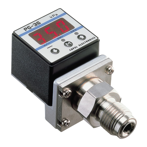
SMALL SIZE PRESSURE GAUGE
PG-35/PG-30
marking
(Compliance with EMC Standards)
Instruction Manual
Important Information and Warnings
①Select either the PG-30 or the PG-35 depending upon the type of pressurized media.
②The maximum impressed pressure of the PG-30-102R at the time of vacuum break is 500kPa.
③For stability, use a regulated direct current power supply.
Surge absorbing devices (diodes,varistors, etc.) are necessary if inductive loads such as relays or solenoids are connected to the same
circuit as the PG-30/PG-35.
If using a DC power supply unit such as a switching power supply, the FG terminal should be earthed. Do not wire in parallel to high
tension cables or power lines, or use cable ducts which contain high tension cables or power lines.
④Be careful not to crimp any wires during handling, or put any pressure on the display area of the main body while assembling piping. The
fitting torque of sealing screws and M5 fitting screws should be 3.0N・m maximum.
⑤Use pH neutral detergents to clean the body. Do not use solvents such as thinners.
⑥This product is dust proof and drip proof (to IP65 of IEC standards) and is not suitable for use in environments requiring higher
standards.
⑦Do not use pointed objects such as pens to press the setting buttons on the display panel, as this may push holes in the setting buttons and
damage them.
⑧Do not insert wires, etc. in the pressure port, as this may damage the internal diaphragm and cause malfunctioning.
⑨PG-35 G3/8 type:
Do not touch or scratch the diaphragm at the edge of the fitting, as this may alter the performance characteristics or damage the
diaphragm, and cause malfunctioning.
⑩PG-35 gasket type:
Do not touch or scratch the edge of the fitting, as this may damage the sealing and
cause leakage.
⑪The PG-30/35 series do not have an explosion proof structure. Do not use it for the
detection of flammable gases.
⑫When analog output is supplied to a noise-sensitive device,a low-pass filter is requested
in a customer's circuit.
⑬Counter measures for noise interference.
Please connect the shielded wire of this product to FG terminal of the power line. (The
shield wire is connected with the metal part inside of the product.)
Thank you for purchasing a
NIDEC COPAL ELECTRONICS CORP. product.
In order to use the product correctly and most
appropriately, please completely read this manual before
use and keep it for future reference.
Ver.9.2
For more detailed information please ask for the nearest
distributor or the following sales center.
Nishi-Shinjuku Prime Square., 7-5-25
Nishi-Shinjuku Shinjuku-ku Tokyo 160-0023, Japan
https://www.nidec-copal-electronics.com
AC input
Power supply unit
Surge absorbing circuit
DC output
F G
F G←The shield wire
+ V
PG30/35
1
Advertisement
Table of Contents

Related Manuals for Nidec PG-35


Summary of Contents for Nidec PG-35
- Page 1 Thank you for purchasing a NIDEC COPAL ELECTRONICS CORP. product. In order to use the product correctly and most SMALL SIZE PRESSURE GAUGE appropriately, please completely read this manual before use and keep it for future reference. PG-35/PG-30 For more detailed information please ask for the nearest distributor or the following sales center. marking (Compliance with EMC Standards) Nishi-Shinjuku Prime Square., 7-5-25 Instruction Manual Nishi-Shinjuku Shinjuku-ku Tokyo 160-0023, Japan Ver.9.2 https://www.nidec-copal-electronics.com Important Information and Warnings ①Select either the PG-30 or the PG-35 depending upon the type of pressurized media. ②The maximum impressed pressure of the PG-30-102R at the time of vacuum break is 500kPa. ③For stability, use a regulated direct current power supply. Surge absorbing devices (diodes,varistors, etc.) are necessary if inductive loads such as relays or solenoids are connected to the same ...
-
Page 2: Specifications
Specifications PG-35 PG-30 Model 102R 103R 102A 101R 102R 103R Type Gauge pressure Absolute pressure Gauge pressure Rated pressure range −100〜100kPa −100〜1000kPa 0〜100kPa ( abs) −10〜10kPa −100〜100kPa −100〜1000kPa Maximum pressure 200kPa 2000kPa 200kPa ( abs) 20kPa 200kPa 1500kPa Break-down pressure 300kPa 3000kPa 300kPa ( abs) 50kPa 500kPa 2000kPa Acceptable media... -
Page 3: Operating Procedures
Operating Procedures Set magnification Setting1 (eleven selections) Initial Pressure Setting2 Operations Set analog output Settings Settings Hysteresis (three selections) Mode Mode Mode (0〜300 digits) Set switch output Digital Filter (eight combinations) (F-0〜F-3) When the power is swiched on, the Operations Mode is automatically selected. Settings remain in effect after switching off the power. Initial Settings Mode +/− +/− +/− +/− Press the and buttons Press the button to move Press the button for Use the and button to set simultaneously to enter the to the next digit. The value more than one second the value of each digit. Initial Settings Mode. of the digit may be set when to return to the the LED below the digit flashes. - Page 4 ■Switch Output Setting The switch output setting is determined by the value of the first digit : the red SW2 LED should be flashing during the setting. Output SW1 output SW2 output There are four operation modes. These are shown in the diagrams below. Mode Separate Window comparator Separate Window comparator Separate Mode Window Comparator Mode Operation (H operation) (A operation) ○ ○ ○ ○ ○ ○ P1:SW1 P2:SW2 ○ ○ ーPr ーPr ○ ○ (L operation) (B operation) ○ ○ ○ ○ ○ ○ P1:SW1 P2:SW2 ーPr Minimum:Setting1...
-
Page 5: Troubleshooting
Troubleshooting ■If the following error messages are displayed, follow the procedures in the table. Display and problem Cause Solution Turn off the power and verify the load Output current is exceeding 100mA. connected switch output 1 and 2. Pressure was applied at the zero point Press M button and return the applied pressure to the adjustment. atmospheric pressure and try zero-point adjustment again. Please contact us. Please use a regulated DC power E-3,E-4 Failure of the internal circuit. supply and measures for the power line noise. 999 Flashing Pressure values exceed the display range. Normal state Pressure values exceed the rated pressure Flashing of the pressure value Normal state range. (110%FS) Non-display mode Normal state (See Non-display mode.) Black out of the display Disable the key operation Key protection mode Normal state (See Key protection mode.) Zero point Adjustment Pressing the and buttons simultaneously in the Operations Mode displays on the screen. One second later this change to than the and buttons are released. (If the pressure port is opened to the atmosphere.) +/− Note:You have to adjust Zero under open air condition. Otherwise you can be seen E‐2 error as you adjusted Zero with residual pressure. 102A mode Zero point is adjusted prior to delivery.(0.3kPa abs max.) Others ■Tube at atmospheric pressure intake If ... -
Page 6: Outline Dimensions
■Key Protection Mode <Key Protection Mode> ・Key Protection Mode is used to lock the front panel key in order to prevent preset values from being accidentally changed. ・Using EEPROM,the PG-30/35 series can retain the preset values even if the power is turned off. (How to set) +/− +/− +/− ・To enable Key Protection Mode,press key for more than 4 seconds. will be displayed and the keys will be locked. ・To disable Key Protection Mode,press key for more than 4 seconds. will be displayed and the keys will be unlocked. Outline Dimensions Unless otherwise specified tolerance : ±0.5(Unit:mm) ■PG-35 Outline Dimensions Fitting part:R2 type □31.4 Air intake 10.5 □30 2−M4 Depth 5 Five core shielded cable L=2000±100 R1/4 (PT1/4) (With M5 female screw) Fitting part: G2 type Fitting part: VC type Fitting part: GF type 9/16-18 UNF G3/8 (PF 3/8) G1/4 (PF1/4) (With M5 female screw) ■PG-35-B Outline Dimensions Fitting part:R2 type □31.4 (65) R1/4 (PT1/4)... -
Page 7: Warranty
V C :9/16-18 UNF (Gasket fitting) P G − 3 5 − 1 0 2 R − N R 2 B Port Blank:Stem mount Model names B : Back mount Switch output type PG-30:Non-corrosive gas type PG-35:High corrosion resistance type N:NPN open collector P:PNP open collector Pressure reference R:Compound pressure ( negative pressure〜positive pressure) A:Absolute pressure ( absolute vacuum〜barometic pressure) 【 PG-35 only】...
Need help?
Do you have a question about the PG-35 and is the answer not in the manual?
Questions and answers