Table of Contents
Advertisement
Quick Links
Introduction
Thank you for purchasing SHIMPO's Digital Tachometer DT-5TXR/ DT-5TFR. For instructions to use this product
properly and optimally for a long period of time, please be sure to read this manual thoroughly before use.
After reading, please store this manual in a safe place for future reference.
When you purchase the product with optional equipment:
Please refer to the optional equipment's operation manual.
Safety Requirements
The following requirements are very important for this product's correct and safe use.
After reading, be sure to store this manual in a safe, convenient place where operators can always refer to it easily.
Electric Shock
Be sure to turn the power OFF when wiring as well
as inspecting the unit.
Otherwise, an electric shock can be caused.
DO NOT touch the unit with wet (or sweaty) hands
for wiring and inspection.
Otherwise, an electric shock can be caused.
■POWER
Make sure AC voltage is between 85 and 264V.(DC powered DT-5TXDR:DC9 to 35V)
When installing unit,keep power and sensor wires separate.
■INPUT SIGNAL WIRE
Connection wiring from sensors shall not be kept in the same or parallel conduit or cable as the power
source, power or high voltage cables to avoid noise which may cause mulfunction.
Use shielded wire for input power connections in the shortest possible metal conduit.
■TERMINAL
After inserting wires tighten terminals securely.
■OPERATING ENVIRONMENT
DO NOT install this unit in the following locations:
Where the unit is exposed to direct sunlight, or where the ambient temperature exceeds a range of 0 - 45
Where the relative humidity exceeds a range of 35 - 85% and where the temperature changes quickly causing
condensation.
Where corrosive and/ or flammable gases are present.
Where levels of dust, salinity, and/ or ferric substance presence are high.
Where direct vibration or impacts can be applied to the unit.
Where the unit can easily be influenced by noises (including static electricity).
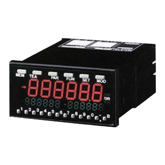
FEATURES:
●Multiple purpose digital tachometer measures
optional, liner, andflowratespeeds. Ifdesired, this
unit can also function as an elapse time counter or
ratiometer.
●An insertion of new cassette type adapter
increases functions.
●All functions are easily set via front panel keys.
●Easy mounting, no brackets or screws are required.
●Any AC voltage between 85 and 264V will power to
DT-5TXAR.(DC powered DT-5TXDR: DC9 to 35V)
Caution
DO NOT block the unit's ventilation holes located on
the sides of the unit. Also, DO NOT put any foreign
matters inside the unit through these holes.
Otherwise, abnormal heat generation or equipment
malfunction can be caused.
In case of assembling the first option to DT-5TXR unit
body after purchasing,
please note that only the options with "R" at the foot
of model name can be connected to the unit.
Operating Environment
1
(CASSETTE TYPE OPTIONAL UNIT)
.
Advertisement
Table of Contents

Related Manuals for Nidec SHIMPO DT-5TXR


Summary of Contents for Nidec SHIMPO DT-5TXR
- Page 1 FEATURES: ●Multiple purpose digital tachometer measures optional, liner, andflowratespeeds. Ifdesired, this unit can also function as an elapse time counter or ratiometer. ●An insertion of new cassette type adapter increases functions. (CASSETTE TYPE OPTIONAL UNIT) ●All functions are easily set via front panel keys. ●Easy mounting, no brackets or screws are required.
-
Page 2: Unit Model
Unit Model Please check your unit's model, as follows. The 2nd Option The 1st Option Power Requirement Input Type * HH: High set point 2 output High set point 1 output Low set point 1 output Low set point 2 output * For combinations of the above-mentioned output levels, refer to DT-5TXR/DT-5TFR Series List;... -
Page 3: Component Part Names And Functions
Component Part Names and Functions ●Front ●Rear * Since, for both DT-5TXR and DT-5TFR series, the optional board(s) are internally equipped, only terminal block (for the 1st optional equipment) or connector (for the 2nd optional equipment) can be viewed from outside of this unit. ●Side External Dimensions Note) When the connector is attached, a 30 mm or more space is required to lay its cable. - Page 4 Unit Attachment to Attachment Panel Refer to the following procedure to attach the unit to the attachment panel. Prior to starting attachment work, be sure to confirm that the attachment panel thickness is 1.2 to 5 mm. Remove the attachment Attach the provided water-proof packing to the panel surface.
- Page 5 Wiring to Power Source and Sensors (DT-5TXR) Note: To prevent an electric shock, prior to performing wiring, be sure to turn the unit's power OFF. Be sure to use the rated voltage (AC power specifications: 85 to 264V AC, DC power specification: 9 to 35V DC). Inverter out- put (to connect a motor) cannot be used as the power source.
- Page 6 Wiring to Power Source and Sensors (DT-5TFR) Note: To prevent an electric shock, prior to performing wiring, be sure to turn the unit's power OFF. Be sure to use the rated voltage (AC power specifications: 85 to 264V AC, DC power specification: 9 to 35V DC). Inverter out- put (to connect a motor) cannot be used as the power source.
-
Page 7: Parameter Settings
Basic Setting Procedure According to each operation mode and application, perform the settings as follows: Parameter Function Mode Settings Measurement start Settings Settings Refer to pages 8 to 12 Refer to pages 8 to 12 Refer to pages 8 to 12 Perform high and low set point 1 value settings (see page 13) or memory function settings (see page 14), whenever required. - Page 8 Mode, Parameter, and Function DT-5TXR/ DT-5TFR has the following five modes. Select an appropriate one according to your measurement purpose. The following parameters and functions have been set up in mode 1 (tachometer mode) upon shipping. ●Parameters (Upon shipping) * When parameter settings are not necessary, the default values (values shown above, designated upon shipping) can be used as is. ●Function (Upon shipping) Note 1) The high set point 2 value is displayed on the sub-display A, and the low set point 2 value, on the sub-B display.
- Page 9 About Hysteresis The output values for the same input differ [Example] when input is increased and decreased. This For high set point 1 value (also applicable phenomenon or the difference between these to low set point 1, high set point 2, and low two amounts is called hysteresis.
- Page 10 Parameters and Functions of Each Mode - 1 Each mode's parameter and function setting items are as follows: ■Mode 1 (Tachometer mode) ●Parameter ●Function * For detailed information about the parameter function, refer to page 8. * For detailed information about the function, refer to page 8. Note 1) The high set point 2 value is displayed on the sub-display A, and the low set point 2 value, on the sub-B display.
- Page 11 Parameters and Functions of Each Mode - 2 Each mode's parameter and function setting items are as follows: ■Mode 3 (Time width mode) ●Parameter ●Function * For detailed information about the function, refer to page 8. Note 1) The high set point 2 value is displayed on the sub-display A, and the low set point 2 value, on the sub-B display.
- Page 12 Parameters and Functions of Each Mode - 3 Each mode's parameter and function setting items are as follows: ■Mode 4 (Flow rate mode) ●Parameter ●Function * For detailed information about the function, refer to page 8. Note 1) The high set point 2 value is displayed on the sub-display A, and the low set point 2 value, on the sub-B display.
- Page 13 High and Low Set Point 1 Values Setup When an output value is larger than the set high set point 1 value, or smaller than the set low set point 1 value, each output display section (see below) lights up. Also, combining with optional equipment, signals can be output*. * High and low set point 1 value evaluation is only displayed.
- Page 14 Memory Function (Maximum and Minimum Value Display) Settings With this function, while performing regular measurement, the maximum (displayed on sub-display A) and minimum (displayed on sub-B display) values can simultaneously be checked. ●Keys used for memory function settings and their functions Used to display the maxi- mum and minimum values.
-
Page 15: Error Display
●Test mode (mode 99) is set up here. Regular display "500.0" is displayed on the main display, "7000," on the sub-display A, and "4000," on the sub-B display. Hold down the [MOD] key for approxi- mately 3 seconds. "500.0" displayed on the main display blinks and the currently T h e m a i n d i s p l a y ' s L E D selected mode's number appears. - Page 16 Optional Equipment (Commonly Used for DT-5TXR/ DT-5TFR) For both DT-5TXR and DT-5TFR, if you purchase a model with optional equipment, be sure to check its model, specifications, and wiring method for the correct use. Caution In case of assembling the first option to DT-5TXR unit body after purchasing, please note that only the options with “R”...
- Page 17 Optional Equipment (Commonly Used for DT-5TXR/ DT-5TFR) For both DT-5TXR and DT-5TFR, if you purchase a model with optional equipment, be sure to check its model, specifications, and wiring method for the correct use. Caution In case of assembling the first option to DT-5TXR unit body after purchasing, please note that only the options with “R”...
- Page 18 Optional Equipment (Commonly Used for DT-5TXR/ DT-5TFR) For both DT-5TXR and DT-5TFR, if you purchase a model with optional equipment, be sure to check its model, specifications, and wiring method for the correct use. ●Specifications ●Wiring (Connector connection) Output circuit * The user must perform cable connection.
- Page 19 Optional Equipment (Commonly Used for DT-5TXR/ DT-5TFR) For both DT-5TXR and DT-5TFR, if you purchase a model with optional equipment, be sure to check its model, specifications, and wiring method for the correct use. ●Specifications ●Wiring (Terminal block connection) Output circuit DT-5TXR/ DT-5TFR Series List This operation manual is applicable to the following models:...
Need help?
Do you have a question about the SHIMPO DT-5TXR and is the answer not in the manual?
Questions and answers