Advertisement
- 1 Symbols Used
- 2 Symbol Description
- 3 Safety Tips
- 4 Product Features
- 5 Device Diagram
- 6 Mounting Instruction
- 7 Wire Connection Sequence
- 8 Monitoring via DC Home or Renogy ONE
- 9 LCD Display Interface Overview
- 10 LCD Status Information
- 11 Key Functionality Chart
- 12 LCD Display Rules & Cycles
- 13 Error Code Chart
- 14 Charging Parameters
- 15 Activate Lithium Batteries
- 16 Specifications
- 17 Dimensions
- 18 Maintenance
- 19 Important Safety Instructions
- 20 Renogy Support
- 21 Documents / Resources
Symbols Used
The following symbols are used throughout the user manual to highlight important information.
 WARNING: Indicates a potentially dangerous condition which could result in injury or death.
 CAUTION: Indicates a critical procedure for safe and proper installation and operation.
 NOTE: Indicates an important step or tip for optimal performance.
Symbol Description
| Icons | Name | Description |
| | High Voltage | High voltage device. Installation should be performed by an electrician. |
 | High Temperature | This device will produce heat. Mount device away from other items. |
 | Wire Cutter | A wire cutter is needed for cutting and stripping wires prior to connection. |
 | Multi-meter | A multimeter is needed for testing equipment and verifying polarity of cables. |
 | Anti-static Glove | Anti-static gloves are recommended to prevent controller damage caused by static electricity. |
 | Electrical Tape | Electrical tape is recommended to safely insulate spliced or bare wires. |
 | Screwdriver | A common size screwdriver is needed to attach wires to the controller. |
Safety Tips
- Review this manual thoroughly before attempting installation.
- Beware of any nearby electrical equipment that may interfere with installing this device.
- Solar panels can generate high voltages and currents, make sure your solar panels are completely covered from sunlight during installation. It is recommended that installation be performed by a quali fied electrician.
- Connecting wires to this device can generate sparks, please wear proper insulation gear while installing this device.
- To avoid damage to the battery or controller, use proper fuses in wiring. Please do not hesitate to contact the professionals if you need help with fuse sizing.
- Always keep children away from this device.
- Be certain to use the correct gauge of wire, see below for a table of recommended wire size for various current loads.
| Solar Input Current | 5A | 10A | 20A | 30A | 40A | 60A |
| Wire Cross Section Area (mm²) | 1.5 | 2.5 | 5 | 8 | 10 | 12 |
| Wire AWG | 15 | 13 | 10 | 8 | 7 | 6 |
Product Features
Thank you for choosing our products. This MPPT solar charge controller is a device for solar charge regulation and direct current output load control. This device is mainly used in small and medium sized off-grid solar power systems.
These MPPT charge controllers have features as follows:
- By continuously checking solar panel power output changes, the controllers employ multiple MPPT charge algorithms in combination to boost charging efficiency in different weather and temperature conditions.
- Built-in buffer, allows max 25% exceeding rated power input.
- Charging modes available for most common deep-cycle battery types in the market, including AGM (sealed lead acid batteries), GEL, Flooded, and Lithium.
- Auto recognition of 12V/24V/36V/48V battery system voltage. Lithium battery excluded from this feature.
- Supports recording of system running data including power generated and power utilized for up to 300 days, compatible with monitoring App through IOS and Android.
- Provides multiple load control mode options for light based, time based and manually adjusted scenarios. Low no-load loss.
- Industrial grade design with reverse polarity protection for solar panels, battery and load.
- After installing the Renogy BT-2 Bluetooth module on this charge controller, you can view the working status of the charge controller through the DC Home APP and RENOGY Core.
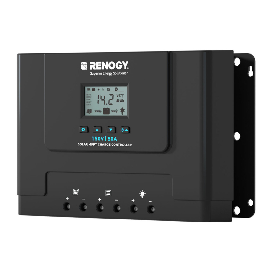
Device Diagram

Mounting Instruction
- Find a cool, dry and weather safe location for installation.
![]()
- Mark the controller's mounting holes on the mounting surface.
![]()
- Drill holes in the marked mounting hole location.
![]()
- Insert pilot screws in the mounting holes.
![]()
- Fasten the controller into the pilot screws.
![]()
- Continue to wire battery. solar DC load and other accessories to the controller
![]()


Wire Connection Sequence

During installation of the controller, please follow the order of connection below:
- Connect the positive battery wire followed by the negative battery wire.
![shock hazard]() Make sure your solar panels are fully covered to prevent electrical shock.
Make sure your solar panels are fully covered to prevent electrical shock.- Connect the positive solar array output wire followed by the negative solar array output wire.
- Connect DC load wires to the DC load output (if applicable).
- Connect the external temperature sensor to its terminal shown above, and attach or stick the temperature sensor to the battery side.
Monitoring via DC Home or Renogy ONE
With a Renogy BT-2 Bluetooth Module, the charge controller can be connected to the DC Home app for remote device monitoring. You can monitor and modify parameters of the charge controller through the DC Home app.

Recommended Components
Components marked with "*" are available on renogy.com.
- Connect the Renogy BT-2 Bluetooth Module to the RS485 Communication Interface on the charge controller. After the connection, the Bluetooth Module POWER indicator light will remain solid green.

- Place the Bluetooth module in a suitable site.

Depending on the specific application, the charge controller can establish either short-range or long-range communication connections with monitoring devices. These monitoring devices facilitate real-time monitoring, programming, and complete system management, offering comprehensive control and enhanced flexibility.
Make sure the Bluetooth of your phone is turned on.
The version of the DC Home app might have been updated. Illustrations in the user manual are for reference only. Follow the instructions based on the current app version.
Make sure that the charge controller is properly installed and powered on before it is paired with the DC Home app.
To ensure optimal system performance, keep the phone within 10 feet (3 m) of the Renogy BT-1 Bluetooth Module or a Renogy BT-2 Bluetooth Module.
To ensure optimal connection performance, download the latest DC Home app. Login to the app with your account.


Short-Range Monitoring
If only short-range monitoring is required, connect the charge controller to the DC Home app directly through the Bluetooth of your phone.

- Open the DC Home app. Tap + to search for new devices.
- Tap Confirm to add the newly found device to the device list.
- Tap the charge controller icon to enter the device information interface.
Wireless Long-Range Monitoring
If long-range communication and programming are required, connect the charge controller to Renogy ONE (sold separately) through Bluetooth, and the Renogy ONE to the DC Home app through Wi-Fi.

Recommended Components
Components marked with "*" are available on renogy.com.
Make sure that the Renogy ONE is powered on before the connection.
For instructions on Renogy ONE, see Renogy ONE Core User Manual.
Make sure the charge controller does not communicate with any other device.

- Connect the charge controller to Renogy ONE through the Bluetooth of your phone.
- Pair the Renogy ONE with the DC Home app by scanning the QR code on Renogy ONE.
LCD Display Interface Overview

| Display Section | Display Layout |
| Active Functions |  |
| Charge Mode & Parameter |  |
| Charge Status |  |
LCD Status Information
| Status Icon | Indication | Status | Description |
 | Solar Charge Indication | Flowing | Solar Power Charging Battery |
| Off | Solar Power Not Charging Battery | ||
 | DC Load Indication | Flowing | DC Load Drawing Power |
| Off | DC Load Off | ||
 | Charge Mode | Steady On | MPPT Charge Mode |
 | Boost Charge Mode | ||
 | Float Charge Mode | ||
| Off | Not Charging | ||
 | Voltage Setting | On | Setting Charge Voltage |
| Off | Charge Voltage Has Been Set | ||
 | Over Discharge Volt Settings | On | Setting Charge Voltage |
| Off | Charge Voltage Has Been Set | ||
 | Solar Icon | Steady On | Daylight Detected |
| Off | No Daylight Detected | ||
| Flash | Solar System Over Voltage | ||
 | Battery Icon | Steady On | Battery Connected and Functional |
| Off | No Battery Connection | ||
| Flash | Battery Over-Discharged | ||
 | Load Status | On | Load On |
| Off | Load Off | ||
| Flash | DC Load Short Circuit or Over-Load |
Key Functionality Chart
| System Mode | Function Key | Input | Input Function |
| View Mode |  | Short Press | View the previous page. |
 | Short Press | View the next page. | |
 | Short Press | DC Load On/Off (Only applicable when the Load Mode is set to "15". For details, see Load Mode Settings.) | |
 | Long Press | Enter Setting Mode. | |
| Set Mode | | Short Press | Increase the parameter value. |
| | Short Press | Decrease the parameter value. | |
| | Short Press | Exit Setting Mode without saving. | |
| | Long Press | Save the settings and exit the Setting Mode. | |
| Short Press | Jump to next parameter settings. |
LCD Display Rules & Cycles
The pre-startup display cycle occurs when the MPPT controller is powered on, typically lasting several seconds, during which the controller assesses the operating environment.

LCD Screen Display Cycle
The battery voltage view will be displayed by default. Use the ![]() and
and ![]() functional keys to cycle through different views. The battery voltage view will resume upon 30 seconds of inactivity. The error code view will be displayed when an error is detected. The backlight in the screen will be on for 20 seconds with any button operation.
functional keys to cycle through different views. The battery voltage view will resume upon 30 seconds of inactivity. The error code view will be displayed when an error is detected. The backlight in the screen will be on for 20 seconds with any button operation.

Setting Battery Mode

Enter Setting mode by pressing the  in any view page other than Load Mode Or Controller Temperature. Use the
  and
and  arrow keys to select battery mode, then long press to save the settings.
| Abbreviations | Battery Types | Description |
 | Flooded Battery | Auto-recognition with default parameters set for each type of batteries. |
 | Sealed/AGM Battery | |
 | Gel Battery | |
 | Lithium Battery (Lithium battery activation disabled) | Low temperature protection (Frozen charge forbid). Some parameters can be customized. |
 | Lithium Battery (Lithium battery activation enabled) | |
 | Advanced User Mode | Most parameters can be customized. |
Advanced Battery Settings
Pressing ![]() to enter Setting mode. Choose LI, ALI or USE mode, short press the
to enter Setting mode. Choose LI, ALI or USE mode, short press the ![]() again to cycle through each parameter view. Use the
again to cycle through each parameter view. Use the ![]() and
and ![]() arrow key to adjust parameter value, then long press
arrow key to adjust parameter value, then long press ![]() to save.
to save.
- Battery Type: LI/ALI
Low Temperature Protection (Low Tem Protect)

- Low Tem Protect Range = 32±9°F (0±5°C)
- Low Tem Protect Range = 5±9°F (-15±5°C)
- When the temperature reaches the protected EN/DIS range, the low-temperature protection will automatically turn on/off after 30 seconds.
- Battery Type: USER


Load Mode Settings

Enter Load Setting Mode by pressing ![]() in Load Mode view only. Use the
in Load Mode view only. Use the  and
and ![]() functional keys to cycle through load modes before long pressing
functional keys to cycle through load modes before long pressing ![]() to save and exit. Short pressing
to save and exit. Short pressing  will exit without saving the settings.
Long press ![]() to save settings and exit the setup interface.
to save settings and exit the setup interface.
Short press to cancel the settings and exit the setup interface.
| Mode | Definition | Description |
| 0 | Daylight Auto-Control | DC load turns on when no daylight is detected. |
| 1 to 14 | Daylight On / Timer Off | DC load turns on when no daylight is detected. DC load turns off according to timer. |
| 15 | Manual Mode | DC load turns on/off by pressing . |
| 16 | Testing Mode | DC load turns on and off in a quick succession. |
| 17 | Always On | DC load stays on. |
Temperature Unit Setting

In the temperature display interface, enter the temperature unit setting mode by long pressing ![]() . You can switch between °F (Fahrenheit) and °C (Celsius) by pressing and
. You can switch between °F (Fahrenheit) and °C (Celsius) by pressing and ![]() functional keys. Long press
functional keys. Long press ![]() to confirm saving and exit, and short press to exit the setting without saving.
to confirm saving and exit, and short press to exit the setting without saving.
Error Code Chart
| Code | Error | Description & Quick Troubleshoot |
| E00 | No Error | No action needed. |
| E01 | Battery Over-discharged | Battery voltage is too low. DC load will be turned off until battery re-charges to recovery voltage. |
| E02 | Battery Over-voltage | Battery voltage has exceeded controller limit. Check battery bank voltage for compatibility with controller. |
| E04 | Load Short Circuit | DC load short circuit. |
| E05 | Load Overload | DC load power draw exceeds controller capability. Reduce load size or upgrade to a higher load capacity controller. |
| E06 | Overheating | Controller exceeds operating temperature limit. Ensure the controller is placed in a well-ventilated cool, dry place. |
| E07 | Environmental Overtemperature | The environment temperature sampled by the external temperature probe is too high. |
| E10 | Solar Over-voltage | Solar array voltage exceeds controller rated input voltage. Decrease the voltage of solar panels connected to the controller. |
| E13 | Solar Reverse Polarity | The solar input wires are connected with reverse polarities. Disconnect and re-connect with correct wire polarities. |
| E14 | Battery Reverse Polarity | Battery connection wires connected with reverse polarity. Disconnect and re-connect with correct wire polarity. |
For further assistance, contact Renogy technical support service at https://www.renogy.com/contact-us.
Charging Parameters
The variable "n" is adopted as a multiplying factor when calculating parameter voltages, the rule for "n" is listed as the following: if battery system voltage is 12V, n=1; 24V, n=2; 36V, n=3; 48V, n=4.
For example, the equalize charge voltage for a 12V FLD (Flooded) battery bank is 14.8V*1=14.8V.
The equalizing charge voltage for a 24V FLD (Flooded) battery bank is 14.8V*2=29.6V.


Activate Lithium Batteries
To enable the lithium battery activation function, set the battery type to ALI on the charge controller. With the function enabled, when the connected lithium battery voltage of the charge controller is 0V, the lithium battery activation function is triggered automatically. The charge controller will activate the lithium battery at a constant voltage of 14.4V (for 12V systems), 28.8V (for 24V systems), 43.2V (for 36V systems), or 57.6V (for 48V systems).
After a period of constant charging, the LCD screen of the charge controller will show AALI, until the charging current from the charge controller to the battery exceeds 300mA. At this point, the lithium battery activation is successful, and the charge controller automatically exits the lithium battery activation mode.

Specifications
| Model | RCC60RVRE |
| System Wiring Grounded | Negative Grounded |
| Battery System Voltage | 12V/24V/36V/48V
|
| No-load Loss |
|
| Max Solar Input Voltage (Voc) | < 150V |
| Rated Solar Charge Current | 60A |
| Max Solar Input Power |
|
| Light Control Voltage | 5V*n |
| Light Control Delay Time | 5mins |
| Rated Load Current | 20A |
| Operating Temperature | -31°F to 113°F / -35°C to 45°C |
| IP Protection | IP32 |
| Net Weight | 7.72 lbs / 3.5 kg |
| Communication Port | RS485 |
| Operating Altitude | ≤ 3000 meters |
| Dimension | 12 × 8.07 × 3.9 in / 305 × 205 × 99 mm |
Dimensions

Dimension tolerance: ±0.2 in (0.5 mm)
Maintenance
Inspection
For optimum performance, it is recommended to perform these tasks regularly.
- Ensure the charge controller is installed in a clean, dry, and ventilated area.
- Ensure there is no damage or wear on the cables.
- Ensure the firmness of the connectors and check if there are any loose, damaged or burnt connections.
- Make sure the indicators are in proper condition.
- Ensure there is no corrosion, insulation damage, or discoloration marks of overheating or burning.
- If the charge controller is dirty, use a damp cloth to clean the outside of the device to prevent dust and dirt from accumulating. Before the charge controller is powered on, make sure it is completely dry after cleaning.
- Make sure the ventilation holes are not blocked.
In some applications, corrosion may exist around the terminals. Corrosion can loosen springs and increase resistance, leading to premature connection failure. Apply dielectric grease to each terminals contact periodically. Dielectric grease repels moisture and protects the terminals contacts from corrosion.
Risk of electric shock! Make sure that all power supplies are turned off before touching terminals on the charge controller.
Cleaning
Follow the steps below to clean the charge controller regularly.
- Disconnect all cables connected to the charge controller.
- Wear proper protective equipment and use insulated tools during operation. Be careful when touching bare terminals of capacitors as they may retain high lethal voltages even after power is removed.
- Wipe the housing of the charge controller and connector contacts with a dry cloth or nonmetallic brush. If it is still dirty, you can use household cleaners.
- Make sure the ventilation holes are not blocked.
- Dry the charge controller with a clean cloth and keep the area around the charge controller clean and dry.
- Make sure the charge controller is completely dry before reconnecting it to the solar panel and battery.
Storage
Follow the tips below to ensure that the charge controller is stored well.
- Disconnect all cables connected to the charge controller.
- By applying dielectric grease to each terminals, the dielectric grease repels moisture and protects the connector contacts from corrosion.
- Store the charge controller in a well-ventilated, dry, and clean environment.
Important Safety Instructions
General
- Wear proper protective equipment and use insulated tools during installation and operation. Do not wear jewelry or other metal objects when working on or around the charge controller.
- Keep the charge controller out of the reach of children.
- Do not dispose of the charge controller as household waste. Comply with local, state, and federal laws and regulations and use recycling channels as required.
![burn hazard]() In case of fire, put out the fire with a FM-200 or CO₂ fire extinguisher.
In case of fire, put out the fire with a FM-200 or CO₂ fire extinguisher.- Installing the charge controller improperly on a boat may cause damage to components of the boat. Have the devices installed by a qualified electrician.
- Do not expose the charge controller to flammable or harsh chemicals or vapors.
- Clean the charge controller regularly.
- Do not puncture, drop, crush, penetrate, shake, strike, or step on the charge controller.
- Do not open, disassemble, repair, tamper with, or modify the charge controller.
- Connect the negative prior to the positive terminal when connecting any device.
- It is recommended that all cables should not exceed 10 meters because excessively long cables result in a voltage drop.
- The cable specifications listed in the quick guide account for critical, less than 3% voltage drop and may not account for all configurations.
Charge Controller Safety
- Install the charge controller on a vertical surface - protected from direct sunlight, high temperatures, and water. Make sure there is good ventilation.
- Keep the charge controller away from heating equipment.
- Do not insert foreign objects into the charge controller.
- Confirm the polarities of the devices before connection. A reverse polarity contact can result in damage to the charge controller, thus voiding the warranty.
- Do not touch the connector contacts while the charge controller is in operation.
- Disconnect all connectors from the charge controller before maintenance or cleaning.
Battery Safety
- Do not use batteries if there is any damage.
- Do not touch the exposed electrolyte or powder if the battery is damaged.
- Risk of explosion! Never install the charge controller in a sealed enclosure with flooded batteries! Do not install the charge controller in a confined area where battery gases can accumulate.
- Prior to installing the charge controller, ensure all battery groups are installed properly.
Solar Panel Safety
- Do not use the solar panel(s) if there is any damage.
- Prior to connecting the charge controller to the solar panel(s), shade the solar panel(s).
- Always connect the charge controller to the battery first before connecting it to the solar panel. This prevents damage caused by open-circuit voltage from the solar panel.
Renogy Support
To discuss inaccuracies or omissions in this quick guide or user manual, visit or contact us at:
renogy.com/support/downloads
contentservice@renogy.com

Questionnaire Investigation
To explore more possibilities of solar systems, visit Renogy Learning Center at:
renogy.com/learning-center
For technical questions about your product in the U.S., contact the Renogy technical support team through:
renogy.com/contact-us
1(909)2877111
For technical support outside the U.S., visit the local website below:
| Canada | ca.renogy.com | China | www.renogy.cn |
| Australia | au.renogy.com | Japan | jp.renogy.com |
| South Korea | kr.renogy.com | Germany | de.renogy.com |
| United Kingdom | uk.renogy.com | Other Europe | eu.renogy.com |
Renogy Empowered
Renogy aims to empower people around the world through education and distribution of DIY-friendly renewable energy solutions.
We intend to be a driving force for sustainable living and energy independence.
In support of this effort, our range of solar products makes it possible for you to minimize your carbon footprint by reducing the need for grid power.
Live Sustainably with Renogy
Did you know? In a given month, a 1 kW solar energy system will...
Save 170 pounds of coal from being burned
Save 300 pounds of CO2 from being released into the atmosphere
Save 105 gallons of water from being consumed
Renogy Power PLUS
Renogy Power Plus allows you to stay in the loop with upcoming solar energy innovations, share your experiences with your solar energy journey, and connect with like-minded people who are changing the world in the Renogy Power Plus community.
![]()
@Renogy Solar
![]()
@renogyofficial
![]()
@Renogy
Manufacturer: RENOGY New Energy Co.,Ltd
Address: No.66, East Ningbo Road Room 624-625
Taicang German Overseas Students Pioneer Park
JiangSu 215000 CN
EC REP
eVatmaster Consulting GmbH
Battinastr.30
60325 Frankfurt am Main, Germany
contact@evatmaster.com
UK REP
EVATOST CONSULTING LTD
Suite 11, First Floor, Moy Road Business
Centre, Taffs Well, Cardiff, Wales, CF15 7QR
contact@evatmaster.com
Documents / Resources
References
RENOGY如果新能源 | 让每个人拥有独立清洁的能源
![renogy.com]() Renogy US Official | Trusted Energy Solutions
Renogy US Official | Trusted Energy Solutions![play.google.com]() Google Play
Google Play![www.apple.com]() App Store - Apple
App Store - Apple![www.renogy.com]() Renogy US Official | Trusted Energy Solutions
Renogy US Official | Trusted Energy Solutions![www.renogy.com]() Contact Us | Renogy Solar Panels and Complete Solar Kits
Contact Us | Renogy Solar Panels and Complete Solar Kits![renogy.com]() Downloads
Downloads![www.renogy.com]() Renogy Learning Center
Renogy Learning Center![renogy.com]() Contact Us | Renogy Solar Panels and Complete Solar Kits
Contact Us | Renogy Solar Panels and Complete Solar Kits![ca.renogy.com]() Renogy CA Official | Trusted Energy Solutions
Renogy CA Official | Trusted Energy Solutions![au.renogy.com]() Renogy AU Official | Trusted Energy Solutions
Renogy AU Official | Trusted Energy Solutions![jp.renogy.com]() Renogy JP 公式サイト| 信頼のエネルギーソリューション
Renogy JP 公式サイト| 信頼のエネルギーソリューション![de.renogy.com]() Renogy DE Official | Trusted Energy Solutions
Renogy DE Official | Trusted Energy Solutions![uk.renogy.com]() Renogy UK Official | Trusted Energy Solutions
Renogy UK Official | Trusted Energy Solutions![eu.renogy.com]() Renogy EU Official | Trusted Energy Solutions
Renogy EU Official | Trusted Energy Solutions
Download manual
Here you can download full pdf version of manual, it may contain additional safety instructions, warranty information, FCC rules, etc.
Advertisement


Need help?
Do you have a question about the RCC60RVRE and is the answer not in the manual?
Questions and answers