Table of Contents
Advertisement
Quick Links
Advertisement
Table of Contents

Related Manuals for Renogy REGO RCC60REGO-US


Summary of Contents for Renogy REGO RCC60REGO-US
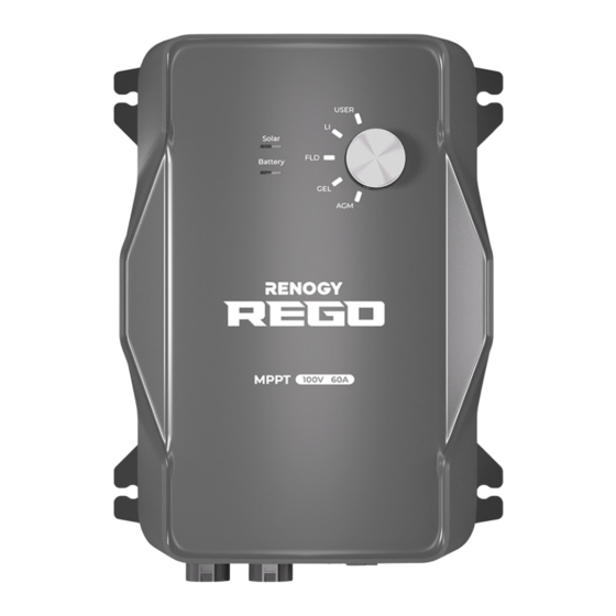
- Page 1 REGO MPPT Solar Charge Controller VERSION A0 USER MANUAL...
- Page 2 REGO 12V 60A MPPT Solar Charge Controller (RCC60REGO) Disclaimer z Renogy makes no warranty as to the accuracy, sufficiency, or suitability of information in the user manual because continuous product improvements are going to be made. z Renogy assumes no responsibility or liability for losses or damages, whether direct, indirect, consequential, or incidental, which might arise out of the use of information in the user manual.
-
Page 3: Table Of Contents
Table of Contents Important Safety Information .......................05 Symbols Used .........................05 General Safety Information .....................05 Overview............................07 Introduction ..........................07 Key Features ...........................07 Charging and Activation Logics ....................08 MPPT Technology ........................08 Four Charging Stages ......................09 Lithium Battery Activation ......................11 Package Contents ........................12 Optional Accessories ........................13 Product Overview ........................14 Wiring Diagram ..........................15 Recommended Cable and Fuse Sizing ..................16... - Page 4 Battery Indicator ........................32 Solar Panel Wiring ........................33 Mounting ............................35 Temperature Sensor ........................36 Voltage Sensor (Optional) ......................37 Communication..........................39 Inter-Device Communication ....................39 Monitoring Device Communication ..................42 Operation ............................47 Setting the Battery Type ......................47 Battery Charging Parameters ....................49 User Mode ..........................50 LED Indicators ..........................53 Troubleshooting ...........................54 Technical Specifications ......................55 MPPT 12V Conversion Efficiency ....................56...
-
Page 5: Important Safety Information
Important Safety Information Symbols Used General Safety Information Important Safety Information The user manual provides important installation, operation, and maintenance instructions for REGO 12V 60A MPPT Solar Charge Controller (hereinafter referred to as charge controller). Read the user manual carefully before installation and operation and save it for future reference. Failure to observe the instructions or precautions in the user manual can result in electrical shock, serious injury, or death, or can damage the charge controller, potentially rendering it inoperable. - Page 6 Important Safety Information Symbols Used General Safety Information z Do not touch the connector contacts while the charge controller is in operation. z Disconnect all connectors from the charge controller before maintenance or cleaning. z Do not dispose of the charge controller as household waste. Comply with local, state, and federal laws and regulations and use recycling channels as required.
-
Page 7: Overview
Overview Introduction Key Features Overview Introduction REGO 12V 60A MPPT Solar Charge Controller can serve various off-grid solar systems. It monitors the status of the battery in real time and prevents the battery from overcharge and overdischarge. The newly added Battery Protection Unit (BPU) prevents fire accidents caused by system failures, further guaranteeing the security of the whole off-grid system. -
Page 8: Charging And Activation Logics
Charging and Activation Logics MPPT Technology Four Charging Stages Lithium Battery Activation Charging and Activation Logics MPPT Technology Based on MPPT (Maximum Power Point Tracking) technology, the charge controller can extract maximum power from the solar panel. With an automatic tracking algorithm, the MPPT technology can track the voltage of the maximum power point that changes with weather conditions, ensuring the harvest of the maximum power throughout the day. -
Page 9: Four Charging Stages
Charging and Activation Logics MPPT Technology Four Charging Stages Lithium Battery Activation Four Charging Stages REGO 12V 60A MPPT Solar Charge Controller has a four-stage battery charging algorithm for a rapid, efficient, and safe battery charging. The stages include: Bulk Charge, Boost Charge, Float Charge, and Equalization. - Page 10 Charging and Activation Logics MPPT Technology Four Charging Stages Lithium Battery Activation charge current would turn into heat or gas. Because of this, the charge controller will reduce the voltage charge to smaller quantity, while lightly charging the battery. The purpose for this is to offset the power consumption while maintaining a full battery storage capacity.
-
Page 11: Lithium Battery Activation
Charging and Activation Logics MPPT Technology Four Charging Stages Lithium Battery Activation Lithium Battery Activation REGO 12V 60A MPPT Solar Charge Controller has the activation function of lithium battery. Lithium batteries may enter sleep mode when the in-built protection is triggered. In such case, the charge controller provides a small current to reactivate the sleeping lithium battery. -
Page 12: Package Contents
REGO 12V 60A MPPT Solar Charge Controller × 1 REGO MPPT Solar Charge Controller VERSION A0 QUICK GUIDE Renogy Temperature Sensor × 1 Solar Adapter Cable (Anderson PP75 to MC4 Adapter Cable) (Model: RTSCC) Mounting Screws × 4 ST 6.3 x 1.8 x 13 mm... -
Page 13: Optional Accessories
Optional Accessories Optional Accessories CAUTION z You can buy optional accessories from renogy.com. Battery Fuse (80A) The battery fuse protects the charge controller, cables and batteries from overcurrent. Solar Panel Fuse Solar panel fuse provides single circuit protection for solar panels, preventing damage from high currents. -
Page 14: Product Overview
Product Overview Product Overview Part Part CAN Communication Ports Positive Battery Terminal Positive Solar Terminal Negative Battery Terminal Battery Temperature Sensor Port Negative Solar Terminal (BTS) Battery Status Indicator Battery Voltage Sensor Port (BVS) Solar Status Indicator Mounting Holes Battery Type Setting Knob... -
Page 15: Wiring Diagram
Wiring Diagram Wiring Diagram Positive Negative Solar Panel Battery... -
Page 16: Recommended Cable And Fuse Sizing
Recommended Cable and Fuse Sizing Recommended Cable Sizing Recommended Fuse Sizing Recommended Cable and Fuse Sizing Recommended Cable Sizing Cable Cable Length (ft) / (m) Recommended Cable Size 0 ft to 10 ft / 0 m to 3 m 8 AWG Solar 11 ft to 20 ft / 3 m to 6 m 6 AWG... - Page 17 Recommended Cable and Fuse Sizing Recommended Cable Sizing Recommended Fuse Sizing INFO z Read the user manual of the solar panel to obtain working voltage parameters, and calculate the corresponding fuse specifications according to the formula. Fuse from Charge Controller to Battery REGO 12V 60A MPPT Solar Charge Controller Battery Fuse (80A)
-
Page 18: Preparation
Preparation Components & Tools CAUTION z The adapter cable used in this manual can be made by yourself or purchased from renogy. according to the names in Recommended Components. Recommended Components Battery Scenario A: REGO Battery Kit Battery Adapter Cables (input) - Page 19 Preparation Components & Tools Checking the Charge Controller Checking Battery Checking Solar Panel Battery Scenario B: Normal Battery Kit Battery Adapter Cables (input / output) Normal Battery with +/- Bolts (Anderson PP75 to Ring Terminal Adapter Cable) Solar Panel Kit Solar Panel Solar Panel Extension Cables...
- Page 20 Preparation Components & Tools Checking the Charge Controller Checking Battery Checking Solar Panel Required Tools Wrench (10 mm) Wrench (14 mm) Insulation Tape Measuring Tape...
-
Page 21: Checking The Charge Controller
Preparation Components & Tools Checking the Charge Controller Checking Battery Checking Solar Panel Checking the Charge Controller 1. Inspect the charge controller for any visible damage including cracks, dents, deformation, and other visible abnormalities. All connector contacts shall be clean, dry, and free of dirt and corrosion. -
Page 22: Checking Battery
Preparation Components & Tools Checking the Charge Controller Checking Battery Checking Solar Panel 3. Measure the length of the cables connecting to the battery and solar panel so they can be connected to the charge controller. NOTE z If the Battery Adapter Cable or Solar Panel Extension Cable is not long enough, you can use more extension cables or reselect the position where the charge controller needs to be secured. -
Page 23: Checking Solar Panel
Preparation Components & Tools Checking the Charge Controller Checking Battery Checking Solar Panel WARNING z Do not use the battery if it has any visible damage. z Do not touch the exposed electrolyte or powder if the battery housing is damaged. z The battery may produce explosive gases when being charged. - Page 24 Preparation Components & Tools Checking the Charge Controller Checking Battery Checking Solar Panel NOTE z The solar panels can be combined in parallel or in series as needed. z Identify the polarities (positive and negative) on the cables used for solar panels. A reverse polarity contact may damage the unit.
-
Page 25: Charge Controller Wiring
Charge Controller Wiring Charge Controller Wiring NOTE z Make sure that the connections of the Anderson connectors are tight and secure. 1. For the Battery terminal, align the Battery Adapter Battery Adapter Cables Cable's Anderson PP75 connectors to the correct orientation and polarity. - Page 26 Charge Controller Wiring 5. For the Solar terminal, align Anderson PP75 connectors of the Solar Adapter Cable to the correct orientation and polarity. 6. Pair the Anderson connectors by sliding the side grooves. 7. Push the protective cover upwards. 8. Insert the Anderson connectors into the Solar terminals.
-
Page 27: Battery Wiring
Battery Wiring Battery Scenario A: REGO Battery Kit Battery Scenario B: Normal Battery Kit Battery Indicator Battery Wiring NOTE z Identify the polarities (positive and negative) on the cables used for the batteries. A reverse polarity contact may damage the unit. z Ensure that the Anderson connectors are fully seated and/or the ring terminals are securely connected. - Page 28 Battery Wiring Battery Scenario A: REGO Battery Kit Battery Scenario B: Normal Battery Kit Battery Indicator █ Using Battery Adapter Cable (Anderson PP75 to Ring Terminal Adapter Cable) NOTE z Select the appropriate wrench according to positive/negative wire fixing bolt specifications of the system hub.
- Page 29 Battery Wiring Battery Scenario A: REGO Battery Kit Battery Scenario B: Normal Battery Kit Battery Indicator Using Positive/Negative Busbars Accessory Set NOTE z Select the applicable wrench according to wire fixing bolt specifications of Positive/Negative Busbars. WARNING z Select the right size of positive/negative sink according to the maximum continuous charging/discharging current of the battery operation.
- Page 30 Battery Wiring Battery Scenario A: REGO Battery Kit Battery Scenario B: Normal Battery Kit Battery Indicator 3. Connect the negative ring terminal of the Battery Adapter Cable to the Negative Busbars and tighten the wire retaining bolt with a wrench. Battery - 4.
-
Page 31: Battery Scenario B: Normal Battery Kit
Battery Wiring Battery Scenario A: REGO Battery Kit Battery Scenario B: Normal Battery Kit Battery Indicator Battery Scenario B: Normal Battery Kit NOTE z Select the appropriate wrench according to the battery positive/negative wire fixing bolt specifications. 1. Attach the ring terminal of the negative Battery Adapter Cable to the negative terminal of... -
Page 32: Battery Indicator
Battery indicator of the charger controller lights up green. When the Battery indicator does not light up, it means the charge controller needs troubleshooting. Read “Troubleshooting” in the user manual. For more instructions, contact our customer service through renogy.com/contact-us/. -
Page 33: Solar Panel Wiring
Solar Panel Wiring Solar Panel Wiring NOTE z Identify the polarities (positive and negative) on the cables used for solar panels. A reverse polarity contact may damage the unit. z Make sure all connections are tight and secure. z Read the “Recommended Cable and Fuse Sizing”... - Page 34 5. Once the solar panel wiring is completed correctly, the Solar indicator of the charger controller lights up green. When the Solar indicator does not light up, it means the charge controller needs troubleshooting. Read “Troubleshooting” in the user manual. For more instructions, contact our customer service through renogy.com/contact- us/.
-
Page 35: Mounting
Mounting Mounting NOTE z Make sure that the charge controller is installed firmly to prevent it from falling off. Place the charge controller against a flat surface and secure it with included screws. -
Page 36: Temperature Sensor
Temperature Sensor Temperature Sensor The temperature sensor can detect the battery temperature and update it to the charge controller for charging voltage calibration. This ensures the charger controller (with operating temperature range from -4°F to 140°F or -20°C to 60°C) can charge the battery normally. CAUTION z Do not use the temperature sensor on a LiFePO4 (LFP) battery which comes with a battery management system (BMS). -
Page 37: Voltage Sensor (Optional)
Voltage Sensor (Optional) Voltage Sensor (Optional) The Battery Voltage Sensor is a perfect solution by providing an accurate battery voltage to the charge controller and allowing it to adjust the charging stage precisely resulting in overall extension of your battery life. Optional Accessories Voltage Sensor NOTE... - Page 38 Voltage Sensor (Optional) 2. Connect the voltage REGO Battery sensor ring terminals to the positive and negative poles of the battery system. Normal Battery with +/- Bolts...
-
Page 39: Communication
Check the RV user manual for details or contact the RV manufacturer if necessary. For technical support from Renogy, please contact us through renogy.com/contact-us/. INFO z Connect devices to the charge controller according to the wiring diagram provided by the RV manufacturer. - Page 40 Communication Inter-Device Communication Monitoring Device Communication 1. Insert the bare wires of the Drop Cables (sold separately) all the way into the wire ports of the Drop Plugs (not included) following the Drop Plug pinout. The red PS+ wires go to pin 1, the white CAN_H wires go to pin 2, the blue CAN_L wires go to pin 3, and the black PS- wires go to pin 4.
- Page 41 Communication Inter-Device Communication Monitoring Device Communication 4. Connect either of the CAN Communication Ports of the charge controller and other REGO devices to the drop sockets on the drop tap with the Drop Cables. NOTE z Different drop taps are used on the RV-C bus by different RV manufacturers. This user manual takes the 4-socket drop tap as an example.
-
Page 42: Monitoring Device Communication
Communication Inter-Device Communication Monitoring Device Communication 2. Plug the Termionator Plugs (sold separately) into the free CAN Communication Ports on the first and last REGO devices. Monitoring Device Communication Depending on the application, the short-range or long-range communication connections can be established between the charger controller and monitoring devices. - Page 43 Inter-Device Communication Monitoring Device Communication Long-Range Monitoring If long-range communication and programming are required, connect the charge controller to Renogy ONE through Bluetooth or wires, and the Renogy ONE to the DC Home app through Wi-Fi. Recommended Accessories Renogy ONE NOTE z Make sure that the Renogy ONE is powered on before the connection.
- Page 44 If you are unsure about the pinout of the terminal block plug, contact the RV manufacturer. “Backbone Topology” section for more instructions. z Refer to the 2. Monitor and program the complete system on Renogy ONE or the DC My Renogy Home app. h left Commonly Security Night...
- Page 45 1. Remove the Terminator Daisy Chain Plug from the REGO Topology device at either end of the daisy chain. 2. Connect the Renogy ONE to the free CAN Communication Port on the REGO device with the Communication Adapter Cable (sold separately).
- Page 46 Communication Inter-Device Communication Monitoring Device Communication 3. Pair Renogy ONE with the DC Home app. Monitor My Renogy and program the complete system on the Renogy h left ONE or the DC Home app. Commonly Security Night Devices Battery Controller RBT12400LFPL-...
-
Page 47: Operation
Operation Setting the Battery Type Battery Charging Parameters User Mode Operation Setting the Battery Type The knob with 5 gears makes the selection of battery type more convenient. Manually set the battery type according to needs. WARNING z Refer to battery manufacturer technical specifications when choosing a preset battery. Incorrect battery type selection resulting in damage will not be covered by warranty. - Page 48 Operation Setting the Battery Type Battery Charging Parameters User Mode 4. If the battery is Lithium Battery, turn the knob to 5. If multiple parameters of the battery need to be programmed, turn the knob to USER to enter the user mode.
-
Page 49: Battery Charging Parameters
Operation Setting the Battery Type Battery Charging Parameters User Mode Battery Charging Parameters WARNING z Before modifying battery parameters, check the table below first. Incorrect parameter setting will damage the device and void the warranty. Battery Type AGM/ USER USER FLOODED LI (LFP) (Default) (Recommended) -
Page 50: User Mode
Operation Setting the Battery Type Battery Charging Parameters User Mode User Mode WARNING z Before modifying battery parameters in user mode, check the table below and consult the battery manufacturer to check whether modification is allowed. Incorrect parameter setting will damage the device and void the warranty. REGO 12V 60A MPPT Solar Charge Controller The default protection voltage is 16V. - Page 51 The version of the DC Home app might have been updated. Illustrations in the user manual are for reference only. Follow the instructions based on the current app version. 1. Open the DC Home app. Tap + to search for new devices. My Renogy Device Battery RBT12400LFPL-...
- Page 52 Operation Setting the Battery Type Battery Charging Parameters User Mode 4. Tap ••• in the upper right corner. ••• NOT CHARGING History PV Screen Total Energy Solar Volts Solar Amps PV Watts Produced 0.052 Battery Charging Volts 13.2 V Battery Charging Amps Battery Type Battery Temperature Sealed...
-
Page 53: Led Indicators
LED Indicators LED Indicators Indicator Color Status Description Green Solar panel detected Solar Status No solar panel detected or the solar panel voltage is too low. For details, “Troubleshooting”. Green Full Green Flashing Charging Yellow Limiting power charging Battery Status Yellow Flashing Equalization charging... -
Page 54: Troubleshooting
Slow flashing red multimeter. for every 1s Battery undervoltage 2. If the battery is low, disconnect all loads from the battery and charge the battery with the solar panel. Solid red The charge controller is Contact our customer service through abnormal. renogy.com/contact-us/. -
Page 55: Technical Specifications
Technical Specifications Technical Specifications Parameter Value Model RCC60REGO Terminal Size Anderson PP75 Terminal Range 6 AWG to 8 AWG Grounding Common Negative Communication CAN Bus Operating Temperature -4°F to 140°F / -20°C to 60°C Storage Temperature -13°F to 149°F / -25°C to 65°C Humidity 0%-90%, RH Cooling... -
Page 56: Mppt 12V Conversion Efficiency
MPPT 12V Conversion Efficiency MPPT 12V Conversion Efficiency Light Intensity: 1000W/m Temperature: 25°C MPPT 12V conversion efficiency (12V battery) 20 Vmp 40 Vmp 60 Vmp 75 Vmp 550 525 500 475 450 425 400 375 350 300 250 200 150 100 50 Output power(W)... -
Page 57: Dimensions
Dimensions Dimensions 7.36in [187mm] 7.44in 9.72in [189mm] [247mm] 6.69in [170mm] 4.29in [109mm] 8.78in [223mm] CAUTION z Dimension tolerance: ±0.2 in (0.5 mm) -
Page 58: Maintenance
Maintenance Inspection Cleaning Storage Maintenance Inspection For optimum performance, it is recommended to perform these tasks regularly. z Check the appearance of the charge controller to make sure it is clean and dry. z Ensure the charge controller is mounted in a clean, dry, and ventilated area. z Ensure there is no damage or wear on the cables. -
Page 59: Emergency Responses
Emergency Responses Fire Flooding Smell Noise Emergency Responses In the event of any threat to health or safety, always begin with the steps below before addressing other suggestions. z Immediately contact the fire department or other relevant emergency response team. z Notify all people who might be affected and ensure that they can evacuate the area. -
Page 60: Technical Support
Technical Support Technical Support For additional support, contact the Renogy technical support team through renogy.com/contact- us. Have the following information available when contacting Renogy. z Owner name z Contact information z Order number z Purchase channel z Serial number z Brief description of the issue Renogy offers premium services worldwide:... - Page 61 FCC Statement This device complies with Part 15 of the FCC Rules. FCC ID: 2ANPBRSMLP4-G2. Operation is subject to the following two conditions: (1) This device may not cause harmful interference. (2) This device must accept any interference received, including interference that may cause undesired operation.
- Page 62 "Contact Us". Renogy reserves the right to change the contents of this manual without notice. Manufacturer: RENOGY New Energy Co.,Ltd Address: No.66, East Ningbo Road Room 624-625 Taicang German Overseas Students Pioneer Park...
Need help?
Do you have a question about the REGO RCC60REGO-US and is the answer not in the manual?
Questions and answers