Sign In
Upload
Download
Table of Contents
Contents
Add to my manuals
Delete from my manuals
Share
URL of this page:
HTML Link:
Bookmark this page
Add
Manual will be automatically added to "My Manuals"
Print this page
×
Bookmark added
×
Added to my manuals
Manuals
Brands
Renogy Manuals
Controller
ROVER ELITE 20A
Manual
Renogy ROVER ELITE 20A Manual
Maximum power point tracking solar charge controller
Hide thumbs
1
2
3
Table Of Contents
4
5
6
7
8
9
10
11
12
13
14
15
16
17
18
19
20
21
22
23
24
25
26
27
28
page
of
28
Go
/
28
Contents
Table of Contents
Troubleshooting
Bookmarks
Table of Contents
Table of Contents
General Information
Product Overview
Identification of Parts
Dimensions
Rover Elite 20A
Rover Elite 40A
Additional Components
Installation
Connect the Charge Controller
Mount the Charge Controller
Cable Sizing
Operation
User Interface
LCD Indicators
Change the Parameters
MPPT Technology
Troubleshooting
Error Codes / Troubleshooting
Protection Behaviors / Fixes
Maintenance
Technical Specifications
Electrical Parameters
General
Battery Charging Parameters
Rover Elite-Conversion Efficiency Curves
Advertisement
Quick Links
1
Rover Elite 20A
2
Rover Elite 40A
3
Connect the Charge Controller
4
Operation
5
Change the Parameters
6
Error Codes / Troubleshooting
Download this manual
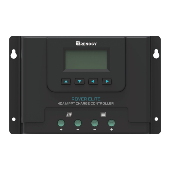
ROVER ELITE
Maximum Power Point Tracking Solar Charge Controller
20A | 40A
Version 1.1
Table of
Contents
Previous
Page
Next
Page
1
2
3
4
5
Advertisement
Table of Contents
Need help?
Do you have a question about the ROVER ELITE 20A and is the answer not in the manual?
Ask a question
Questions and answers
Related Manuals for Renogy ROVER ELITE 20A
Controller Renogy ROVER Series Installation And Operation Manual
Maximum power point tracking solar charge controller (104 pages)
Controller Renogy ROVER Series Manual
Mppt solar charge controller (64 pages)
Controller Renogy Rover Series Manual
Maximum power point tracking solar charge controller (36 pages)
Controller Renogy Rover Series Manual
Maximum power point tracking solar charge controller (36 pages)
Controller Renogy ROVER Series Manual
Maximm power point tracking solar charge controller (45 pages)
Controller Renogy ROVER BOOST Manual
Maximum power-point tracking boost charge controller 36v/48v 10a (36 pages)
Controller Renogy ROVER ELITE 40A Manual
Maximum power point tracking solar charge controller (28 pages)
Controller Renogy Rover Li Series User Manual
Mppt solar charge controller (76 pages)
Controller Renogy Rover PG Series Manual
Maximum power point tracking solar charge controller (28 pages)
Controller Renogy RNG-CTRL-MPPT20 User Manual
Mppt tracer series maximum power point tracking solar charge controller (32 pages)
Controller Renogy RVR60 Manual
Maximum power point tracking solar charge controller (36 pages)
Controller Renogy RCC10RVRB Manual
Maximum power-point tracking boost charge controller 36v/48v 10a (36 pages)
Controller Renogy WANDERER Manual
Lcd pwm solar charge controller 10a | 12v/24v (28 pages)
Controller Renogy REGO User Manual
Mppt solar charge controller (41 pages)
Controller Renogy RCC40RVRE-G1 Manual
Maximum power point tracking solar charge controller (28 pages)
Controller Renogy Rover RNG-CTRL-RVR60-G1 User Manual
60 amp mppt solar charge controller (63 pages)
This manual is also suitable for:
Rover elite 40a
Rcc20rvre-g1
Rcc40rvre-g1
Table of Contents
Print
Rename the bookmark
Delete bookmark?
Delete from my manuals?
Login
Sign In
OR
Sign in with Facebook
Sign in with Google
Upload manual
Upload from disk
Upload from URL


Need help?
Do you have a question about the ROVER ELITE 20A and is the answer not in the manual?
Questions and answers