
Subscribe to Our Youtube Channel
Related Manuals for Renogy Rover PG Series


Summary of Contents for Renogy Rover PG Series
- Page 1 Rover PG Series Rover PG 20A | 30A | 40A Maximum Power Point Tracking Solar Charge Controller Version 1.0...
- Page 2 Important Safety Instructions Please save these instructions. This manual contains important safety, installation, and operating instructions for the charge controller. The following symbols are used throughout the manual to indicate potentially dangerous conditions or important safety information. Indicates a potentially dangerous condition. Use extreme caution WARNING when performing this task Indicates a critical procedure for safe and proper operation of the...
- Page 3 Battery Safety Use only sealed lead-acid, flooded, gel or lithium batteries which must be deep cycle. Explosive battery gases may be present while charging. Be certain there is enough ventilation to release the gases. Be careful when working with large lead acid batteries. Wear eye protection and have fresh water available in case there is contact with the battery acid.
-
Page 4: Table Of Contents
Table of Contents General Information Additional Components Optional Components Identification of Parts Installation Operation LED Indicators Rover PG Protections System Status Troubleshooting Error Codes Maintenance Fusing Technical Specifications Electrical Parameters General Battery Charging Parameters ROVER PG: PV Power – Conversion Efficiency Curves Dimensions... -
Page 5: General Information
General Information The Rover PG Series charge controllers are intelligent positive ground controllers suitable for various off-grid solar applications. It protects the battery from being over-charged by the solar modules and over-discharged by the loads. The controller features a smart tracking algorithm that maximizes the energy from the solar PV module(s) and charge the battery. - Page 6 Therefore, assuming 100% efficiency: Power In = Power Out Volts In * Amps In = Volts out * Amps out Although MPPT controllers are not 100% efficient, they are very close at about 92-95% efficient. Therefore, when the user has a solar system whose Vmp is greater than the battery bank voltage, then that potential difference is proportional to the current boost.
- Page 7 Four Charging Stages The Rover PG MPPT charge controller has a 4-stage battery charging algorithm for a rapid, efficient, and safe battery charging. They include: Bulk Charge, Boost Charge, Float Charge, and Equalization. Bulk Charge: This algorithm is used for day to day charging. It uses 100% of available solar power to recharge the battery and is equivalent to constant current.
- Page 8 The charge controller will reduce the voltage charge to smaller quantity, while lightly charging the battery. The purpose for this is to offset the power consumption while maintaining a full battery storage capacity. In the event that a load drawn from the battery exceeds the charge current, the controller will no longer be able to maintain the battery to a Float set point and the controller will end the float charge stage and refer back to bulk charging.
-
Page 9: Additional Components
The BT-1 Bluetooth module is a great addition to any Renogy charge controllers with a RS232 port and is used to pair charge controllers with the Renogy BT App. After pairing is done you can monitor your system and change parameters directly from you cell phone or tablet. No more wondering how your system is performing, now you can see performance in real time without the need of checking on the controller’s LCD. -
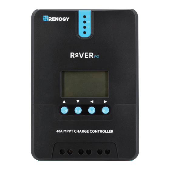
Page 10: Identification Of Parts
Identification of Parts ○ ○ ○ ○ ○ ○ ○ ○ ○ ○ ○ ○ Key Parts 1. PV LED Indicator 2. Battery LED Indicator 3. Load LED Indicator 4. System Error LED Indicator 5. LCD Screen 6. Operating Keys 7. -
Page 11: Installation
Installation Recommended tools to have before installation: Screwdriver Multi-Meter Connect battery terminal wires to the charge controller FIRST then connect the WARNING solar panel(s) to the charge controller. NEVER connect solar panel to charge controller before the battery. Do NOT connect any inverters or battery chargers into the LOAD TERMINAL of WARNING the charge controller. - Page 12 Battery...
- Page 13 Load (optional) Solar Panels...
- Page 14 PC or Bluetooth Module communication (optional) Temperature Sensor (optional, not polarity sensitive) Secure the Temperature Sensor lug to one of the battery posts Do NOT place the Temperature Sensor lug inside the battery cell. NOTE Mounting Recommendations WARNING Never install the controller in a sealed enclosure with flooded batteries. Gas can accumulate and there is a risk of explosion.
-
Page 15: Operation
2. Check for Clearance—verify that there is sufficient room to run wires, as well as clearance above and below the controller for ventilation. The clearance should be at least 6 inches (150mm). 3. Mark Holes 4. Drill Holes 5. Secure the charge controller. Operation Rover PG is very simple to use. - Page 16 Main Display Main Screen Solar Panel Voltage Charging Current Battery Voltage Battery Capacity Error Code Accumulated AH Load Current Load mode Ambient Temperature Discharged AH NOTE The Battery Capacity (SOC%) is an estimation based on the charging voltage.
- Page 17 “USER” mode. Press and hold the right arrow to enter the programming settings and continue pressing the right arrow button until you see the desired voltage screen. NOTE Battery charging parameters can also be programmed using Solar Monitoring Software and Renogy BT APP. Read the corresponding user manuals for more information.
- Page 18 Programming Load Terminal 1. This screen is displaying the current Load Mode. 2. To enter screen 2 press and hold the Enter button. This screen will allow you to change the load mode. 3. To change the load mode press the up or down button. 4.
-
Page 19: Led Indicators
LCD Indicators nighttime daytime solar panel charging battery discharging load parameter value charging stage system voltage setting serial port bluetooth abnormality battery type unit LED Indicators Indicating the controller's current ①---PV array indicator charging mode. ②---BAT indicator Indicating the battery's current state. Indicating the loads' On/ Off state. - Page 20 PV Indicator (1) Status White Solid The PV system is charging the battery bank White Slow Flashing The Controller is undergoing boost stage White Single Flashing The Controller is undergoing float stage White Fast Flashing The Controller is undergoing equalization stage The PV system is charging the battery bank at a slow rate.
-
Page 21: Rover Pg Protections
Rover PG Protections Protection Behavior When PV shot circuit occurs, the controller will stop charging. PV Array Short Circuit Clear it to resume normal operation. If the PV voltage is larger than maximum input open voltage 100VDC, PV will remain disconnected until the voltage drops PV Overvoltage below 100VDC. -
Page 22: System Status Troubleshooting
System Status Troubleshooting PV indicator Troubleshoot Ensure that the PV wires are correctly and tightly secured inside the charge controller PV terminals. Use a multi-meter to make sure the Off during daylight poles are correctly connected to the charge controller. BATT Indicator Troubleshoot Disconnect loads, if any, and let the PV modules charge the battery bank. -
Page 23: Maintenance
Maintenance Risk of Electric Shock! Make sure that all power is turned off before touching the WARNING terminals on the charge controller. For best controller performance, it is recommended that these tasks be performed from time to time. 1. Check that controller is mounted in a clean, dry, and ventilated area. 2. -
Page 24: Technical Specifications
Technical Specifications Electrical Parameters Model RVRPG-20 RVRPG-30 RVRPG-40 Nominal system voltage 12V/24V Auto Recognition Rated Battery Current Rated Load Current Max. Battery Voltage Max Solar Input Voltage 100 VDC 12V @ 260W 12V @ 400W 12V @ 520W Max. Solar Input Power 24V @ 520W 24V @ 800W 24V @ 1040W... -
Page 25: Battery Charging Parameters
1-10 Hrs. *Battery charging parameters in LI mode and USER mode can be programmed using the Solar Monitoring Software or Renogy BT App. **Default charging parameters in LI mode are programmed for 12.8V LFP battery. Before using Rover PG to charge other types of lithium battery, set the parameters according to the suggestions from battery manufacturer. -
Page 26: Rover Pg: Pv Power - Conversion Efficiency Curves
Rover PG– Conversion Efficiency Curves Illumination Intensity: 1000W/ m Temp 25℃ 1.12 Volt System Conversion Efficiency MPPT 12V conversion efficiency (12V battery) Output power(W) 2. 24 Volt System Conversion Efficiency MPPT 24V conversion efficiency (24V battery) Output power(W)... -
Page 27: Dimensions
Dimensions RVRPG-20 59.5 4xφ3 4xφ9 Product dimensions: 210*151*59.5mm Hole positions: 154*131mm Hole diameter: Ø3mm Maximum Wire Gauge 10 AWG 143.6 Dimensions in millimeters (mm) NOTE RVRPG-30/40 72.5 4xφ10 4xφ3 Product dimensions: 238*173*72.5mm Hole positions: 180*147mm Hole diameter: Ø3mm Maximum Wire Gauge 8 AWG 123.5 Dimensions in millimeters (mm) NOTE... - Page 28 2775 E. Philadelphia St., Ontario, CA 91761 1-800-330-8678 Renogy reserves the right to change the contents of this manual without notice.
Need help?
Do you have a question about the Rover PG Series and is the answer not in the manual?
Questions and answers