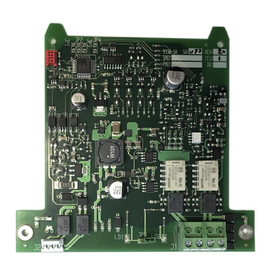
Summary of Contents for Panasonic 4585
- Page 1 4585 COM-LOOP REPEATER Fire alarm solutions technical description www.panasonic-fire-security.com...
-
Page 2: Table Of Contents
5.3. CHANGE THE COM LOOP ADDRESS 5.4. RESET ADDRESS SET THE MODE 6.1. COMPATIBILITY TABLE MOUNTING INSTALLATION AND WIRING 8.1. 4585 CONNECTIONS TO ADDRESSABLE DEVICES 8.2. CONNECTIONS TO 4466, MOLEX CONNECTOR J2 8.3. CONNECTIONS FOR SUB-LOOP, TERMINAL BLOCK J1 TECHNICAL DATA APPROVALS... -
Page 3: Introduction
4585 COM-LOOP REPEATER - FIRE ALARM SOLUTIONS TECHNICAL DESCRIPTION 1. INTRODUCTION This document describes the COM-loop repeatert, type number 4585. The document contains information about the product and instructions on how to mount and connect it. -
Page 4: Abbreviations
2. ABBREVIATIONS Control and indicating equipment = control unit Input/Output Light Emitting Diode nanofarad Printed circuit board Relative humidity Software... -
Page 5: General Description
24 V DC via the External power supply 4466. The 4585 has no short circuit isolator, but is protected against short circuits on the COM-loop via the short circuit isolator in 4466. The COM-loop repeater has a terminal block for cable connections to the SUB-loop. -
Page 6: Led 1
LED 1 is lit red when the board is not yet addressed, and also lit red during manual address reset by jumper JP5. 3.1.1. TOGGLE LED LED 1 is lit red when activating 'Toggle LED'. The 4585 supports the function 'Toggle LED' via EBLWin. For more information, see Planning Instructions for the system. 3.2. LED 2 LED 2 is lit green when the communication on the SUB-loop is ok. -
Page 7: Functional Overview
4585 COM-LOOP REPEATER - FIRE ALARM SOLUTIONS TECHNICAL DESCRIPTION 3.6. FUNCTIONAL OVERVIEW This overview is an example of how the COM-loop repeater 4585 can be used. 1. COM-loop (internally via 4466) 2. Power (internally via 4466) 3. SUB-loop 4. Addressable COM-loop units 5. -
Page 8: Configuration
4. CONFIGURATION The 4585 needs to be added into the configuration, manually or via auto addressing function. For more information, see the Planning Instructions for the system. In the COM-loop repeater 4585 unit properties window, set the following: • Technical address: Automatically set if auto addressing is used. -
Page 9: Summary Of Loop Units
4585 COM-LOOP REPEATER - FIRE ALARM SOLUTIONS TECHNICAL DESCRIPTION 4.2. SUMMARY OF LOOP UNITS The units that are added in the tree view are also summarized in the 'Summary of loop units' tab. • Type • Amount • Quiescent consumption (current) •... -
Page 10: Set The Com Loop Address
CHECK LOOP If a 4585 unit without address is found during check loop, the CIE will report it to EBLWin with the correct address, i.e. the address of the 4466 unit plus one or two. This way, a correct SSD can be created after the check loop procedure is finished. -
Page 11: Change The Com Loop Address
5.3. CHANGE THE COM LOOP ADDRESS If the COM loop address for 4466 must be changed, the address for 4464 and 4585 also must be changed (if mounted). a) Disconnect the 4466 from the COM loop. b) Reset the address for PCB 4464/4585 according to the instruction on page 11. -
Page 12: Set The Mode
6. SET THE MODE The mode is automatically set to Advanced mode during auto addressing. 6.1. COMPATIBILITY TABLE Advanced mode NORMAL mode 2330 mode 2312 mode EBL512 G3 V ≥ 2.5 Not used Not used Not used EBL128 Not used Not used Not used Not used... -
Page 13: Mounting
4585 COM-LOOP REPEATER - FIRE ALARM SOLUTIONS TECHNICAL DESCRIPTION 7. MOUNTING One or two expansion boards 4585 can be mounted on the charger board, inside the 4466. a) Mount the expansion boards according to the picture below. Screws are supplied with the expansion boards. -
Page 14: Installation And Wiring
Wire size (Min) Ø 0.65 mm (0.33 mm²) Wire size (Max) Ø 1.6 mm (2 mm²) 8.1. 4585 CONNECTIONS TO ADDRESSABLE DEVICES See Technical Description for each unit. 8.2. CONNECTIONS TO 4466, MOLEX CONNECTOR J2 1. +24V DC 2. 0V 3. -
Page 15: Technical Data
4585 COM-LOOP REPEATER - FIRE ALARM SOLUTIONS TECHNICAL DESCRIPTION 9. TECHNICAL DATA All current consumptions are valid by nominal voltage and by 25 °C. Voltage: The 4585 unit is power supplied from the 4466. Allowed 16 – 30.0V DC Normal... -
Page 16: Approvals
10. APPROVALS Applicable directive/ Approval Applicable standards Notified body EN54-18 No. 0786-CPR-21627 EN54-18 VdS 2344 No. G219025 VdS 2503 EN55032 (Emission) Self declaration EN50130-4 (Immunity) RoHS EN IEC 63000 Self declaration... - Page 17 DOCUMENT NAME: TECHNICAL DESCRIPTION 4585 DOCUMENT NUMBER: MEW02105 EN DATE OF ISSUE: 2019-04-10 REV: 2 DATE OF REVISION: 2022-06-13 Panasonic Fire & Security Europe AB Jungmansgatan 12 SE-211 11 Malmö Tel: +46 (0)40 697 70 00 www.panasonic-fire-security.com...


Need help?
Do you have a question about the 4585 and is the answer not in the manual?
Questions and answers