Table of Contents
Advertisement
Quick Links
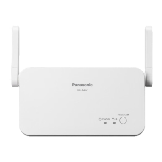
Installation Manual
Repeater
KX-A407
Model No.
Thank you for purchasing this Panasonic product.
Please read this manual carefully before using this product and save this manual for future
use.
Note
• In this manual, the suffix of each model number is omitted unless necessary.
Document Version: 2020-01
Advertisement
Table of Contents

Related Manuals for Panasonic KX-A407 Series


Summary of Contents for Panasonic KX-A407 Series
- Page 1 Installation Manual Repeater KX-A407 Model No. Thank you for purchasing this Panasonic product. Please read this manual carefully before using this product and save this manual for future use. Note • In this manual, the suffix of each model number is omitted unless necessary.
- Page 2 Related Documentation • Quick Start Guide Describes setup and safety information of the unit. Manuals and supporting information are provided on the Panasonic Web site at: https://panasonic.net/cns/pcc/support/sipphone/ Note The contents and design of the software are subject to change without notice.
-
Page 3: Table Of Contents
Table of Contents Table of Contents Important Information ............4 Important Information ................... 4 For best performance ................... 7 Overview ................9 Overview ......................9 System Connection Example ............... 9 Location of Controls ................... 11 Included Accessories ................. 11 Indicators ..................... 12 Repeater ID Confirmation ................ -
Page 4: Important Information
1 Important Information 1 Important Information 1.1 Important Information CAUTION SECURITY REQUIREMENTS Preventing Data Disclosure Over the Network • To ensure the security of private conversations, only connect the product to a secure network. • To prevent unauthorized access, only connect the product to a network that is properly managed. - Page 5 For Users in European countries The following declaration is applicable to KX-A407CE/KX-A407UK only Hereby, Panasonic Corporation declares that the radio equipment described in this manual is in compliance with Directive 2014/53/EU. The full text of the EU declaration of conformity is available at the following internet address: https://www.ptc.panasonic.eu/compliance-documents...
- Page 6 1.1 Important Information Note This equipment has been tested and found to comply with the limits for a Class B digital device, pursuant to Part 15 of the FCC Rules. These limits are designed to provide reasonable protection against harmful interference in a residential installation. This equipment generates, uses, and can radiate radio frequency energy and, if not installed and used in accordance with the instructions, may cause harmful interference to radio communications.
-
Page 7: For Best Performance
1.2 For best performance Repeater location/avoiding noise The repeater and other compatible Panasonic products use radio waves to communicate with each other. • For maximum coverage and noise-free communications, place your repeater: –at a convenient, high, and central location with no obstructions between the handset and repeater in an indoor environment. - Page 8 1.2 For best performance • The maximum calling distance may be shortened when the repeater is used in the following places: Near obstacles such as hills, tunnels, underground, near metal objects such as wire fences, etc. • Operating the repeater near electrical appliances may cause interference. Move away from the electrical appliances.
-
Page 9: Overview
2 Overview 2 Overview 2.1 Overview A repeater is used when you need to extend the range of a handset to include areas where reception was previously not available. The repeater extends the range in all directions, allowing several floors to be covered. Note •... - Page 10 2.2 System Connection Example Repeater Coverage Area As a guideline, the example below shows the size of the coverage area where one repeater can synchronize with a base unit/destination repeater, or provide coverage for a handset, if it is installed in an area with no obstacles. Note •...
-
Page 11: Location Of Controls
2.3 Location of Controls 2.3 Location of Controls STATUS Indicator RSSI/ID Indicator The RSSI (Received Signal Strength Indicator) shows the strength of the wireless network. Throughout this manual, the term "RSSI/ID" refers to PROGRAM Button Used to power off the repeater, or to switch to Operation Mode, ID Confirmation mode, De-registration Mode or Site Survey Mode. -
Page 12: Indicators
2.5 Indicators 2.5 Indicators The indicator patterns and the corresponding status of the repeater in each mode are as follows. Indicators Mode Status STATUS RSSI/ID Power Off Hardware Error Quick — Amber Flashing Entering De-registration mode (0–5 seconds Flashing De-registration Entering Site Survey mode (5–10 Quick Red Mode... - Page 13 2.5 Indicators Indicators Mode Status STATUS RSSI/ID 1 Green Flash 2 Green Flashes 3 Green ID Confirmation Flashes Mode (Program Amber On 4 Green Key) Flashes 5 Green Flashes 6 Green Flashes ID Confirmation Signal is strong 3 Amber Green On Mode (Remote) Flashes Signal is weak...
- Page 14 2.5 Indicators Indicators Mode Status STATUS RSSI/ID Channel 6 (signal is strong) 6 Green Green ON Flashes Channel 6 (signal is weak) Amber ON Out of range Red ON Channel 7 (signal is strong) 7 Green Green ON Flashes Channel 7 (signal is weak) Amber ON Out of range Red ON...
-
Page 15: Repeater Id Confirmation
2.6 Repeater ID Confirmation Type of Flashing Speed Regular Flashing 640 ms On → 640 ms Off Quick Flashing 320 ms On → 320 ms Off 1 Flash Regular Flashing → 3 s Off 2 Flashes Regular Flashing × 2 → 3 s Off 3 Flashes Regular Flashing ×... -
Page 16: Site Survey
2.7 Site Survey Select the repeater ID to confirm the target repeater, and press The target repeater's Status LED will flash amber at 3 times. 2.7 Site Survey This function can be used to measure the transmission quality, and identify problematic transmission areas of the repeater installation. - Page 17 2.7 Site Survey The channel number will change by one each time the PROGRAM button is pressed. To turn off Site Survey mode, turn off the repeater by disconnecting the AC adaptor, and then turn on the repeater by connecting the AC adaptor.
-
Page 18: Linking To Sip Cordless Phones
3 Linking to SIP Cordless Phones 3 Linking to SIP Cordless Phones 3.1 Linking to SIP Cordless Phones This section describes how to use the repeater to connect SIP cordless phone base units and handsets. 3.2 Compatible Devices Compatible Device Model No. -
Page 19: Installation/Registering The Repeater
For registering and deregistering the repeater, refer to "Deregister" and "Re-register" in "3.5 Troubleshooting". Note • Use only the supplied Panasonic AC adaptor. • When connecting the AC adaptor to the repeater, press the plug firmly into the repeater for secure connection. - Page 20 3.4 Installation/Registering the Repeater Base unit: Press and hold the Handset locator button for about 4 seconds until the STATUS indicator flashes red. • The button and indicator depend on the base unit. • If all registered handsets start ringing, press the same button to stop. Then repeat this step.
- Page 21 3.4 Installation/Registering the Repeater Cascade Configuration In manual registration, the repeater can be registered to another repeater to create a cascade configuration. Note • The following limitations apply when the KX-A407 (repeater) is connected to a KX-TGP700 base unit. –Narrowband mode: Up to 3 KX-A407 units can be connected in a cascade configuration, and up to 8 calls can be made simultaneously.
- Page 22 3.4 Installation/Registering the Repeater Repeater: Plug the AC adaptor to reset the repeater. Base unit: Press and hold the Handset locator button for about 4 seconds until the STATUS indicator flashes red. Repeater: When the repeater has found a repeater with the assigned ID, the STATUS indicator will turn green.
-
Page 23: Troubleshooting
3.5 Troubleshooting 3.5 Troubleshooting Problem Cause/solution The repeater does not work. • When the indicators do not turn on, the AC adaptor is not connected properly. Check the connections. • When the indicators do not turn green, move the repeater closer to the base unit. •... - Page 24 3.5 Troubleshooting Problem Cause/solution The repeater’s STATUS • The ID of the repeater is the same as the ID of indicator and RSSI/ID indicator another repeater that is registered to the same flash green and red alternately base unit. (alarm indication). Deregister both of the repeaters, then re-register them near the base unit.
-
Page 25: Appendix
4 Appendix 4 Appendix 4.1 Appendix This section describes about mounting the repeater on a wall and its specifications. 4.2 Wall Mounting Mounting CAUTION • Make sure the cable is securely fastened to the wall. Place the reference for wall mounting on the wall to mark the 2 screw positions. Install the 2 screws and washers (included) into the wall. - Page 26 4.2 Wall Mounting Reference for Wall Mounting Print this page and use as a reference for wall mounting. 85 mm Install a screw here. Note Make sure to set the print size to correspond with the size of this page. If the dimension of the paper output still deviates slightly from the measurement indicated here, use the measurement indicated here.
-
Page 27: Specifications
4.3 Specifications 4.3 Specifications Basic Specifications Maximum Number of Simultaneous Calls Maximum Number of Cascade Steps Maximum Number of Repeaters Registered to a base unit The maximum number of simultaneous calls is 4 when connecting with KX-TGP700 base units, or using wideband audio codec G.722 or G.722.2. Cascade connections are not available when connecting with KX-TGP700 base units. - Page 28 4.3 Specifications Frequency Band KX-A407 1920 MHz to 1930 MHz KX-A407CE/KX-A407UK/KX-A407AL 1880 MHz to 1900 MHz Number of Carriers KX-A407 KX-A407CE/KX-A407UK/KX-A407AL Carrier Spacing 1728 kHz Bit Rate 1152 kbps Modulation Scheme GFSK Transmission Output KX-A407 Peak 0.11 W KX-A407CE/KX-A407UK/KX-A407AL Peak 0.25 W The wireless interface differs according to the country/area.
- Page 29 Panasonic Corporation 1006, Oaza Kadoma, Kadoma-shi, Osaka 571-8501, Japan https://panasonic.net/cns/pcc/support/sipphone/ Panasonic Corporation of North America Two Riverfront Plaza, Newark, New Jersey 07102-5490 https://panasonic.net/cns/pcc/support/sipphone/ Panasonic Canada Inc. 5770 Ambler Drive, Mississauga, Ontario, L4W 2T3 http://www.panasonic.com/ca/ © Panasonic Corporation 2020 PNQX8949ZA PP0420HY0...
Need help?
Do you have a question about the KX-A407 Series and is the answer not in the manual?
Questions and answers