S&C VacuFuse II Quick Operation Manual
Self-resetting interrupter
Hide thumbs
Also See for VacuFuse II:
- Instruction sheet (23 pages) ,
- Quick operation manual (2 pages) ,
- Installation and operation manual (23 pages)
Advertisement
Table of Contents
- 1 Understanding the LED Indicators and POSITION Indicator
- 2 Installing a Vacufuse II Interrupter into the Cutout Mounting
- 3 Understanding the Closing Sequence
- 4 Closing the Vacufuse II Interrupter into the Cutout Mounting
- 5 If the Vacufuse II Self-Resetting Interrupter Is Found Open
- 6 If Maintenance Is to be Performed on the Transformer
- 7 Opening and Closing the Vacufuse II Interrupter
- 8 Removing the Vacufuse II Interrupter from the Cutout Mounting
- Download this manual
VacuFuse
II Self-Resetting Interrupter—Quick Operation Guide
®
Outdoor Distribution (12.47 kV through 27.0 kV)
WARNING
VacuFuse II Self-Resetting Interrupters must be installed, operated, and maintained
by qualified persons knowledgeable in overhead electric power distribution equipment
and the associated hazards. This guide is not a replacement for adequate training
and experience in safety procedures for this product. Read S&C Instruction Sheet
466-500 thoroughly and carefully before installing or operating your VacuFuse II
Self-Resetting Interrupter.
DANGER
VacuFuse II Self-Resetting Interrupters may be energized from either side and in any
position. Always consider all parts live until de-energized, tested, and grounded.
Understanding the Closing Sequence
Note: The VacuFuse II Self-Resetting Interrupter is shipped from the factory with the
vacuum interrupter in the Open position.
When closing the VacuFuse II Self-Resetting Interrupter into the cutout mounting
the CHARGING LED will blink at a one-second interval as long as there is sufficient
voltage present in the cutout mounting and the vacuum interrupter is open. The READY
TO CLOSE LED will steadily illuminate when the VacuFuse II interrupter has harvested
enough energy to close the vacuum interrupter and when the manual operating lever is
in the Down position.
The VacuFuse II Self-Resetting Interrupter requires 45 ± 10 seconds to harvest enough
energy to close the vacuum interrupter.
There are two ways to close the vacuum interrupter:
Option 1: Automatic Delayed Close
Place the manual operating lever into the Up position at any time prior to closing the unit
into the cutout mounting, or less than 35 seconds after the CHARGING LED has begun
blinking. When closed into the cutout mounting in this state, the CHARGING LED will
blink at a one-second interval if there is sufficient voltage present in the cutout mounting
and the vacuum interrupter is open. The VacuFuse II interrupter will automatically close
the vacuum interrupter after 45 ±10 seconds.
Option 2: Manual Close
Place the manual operating lever into the Down position prior to closing the unit into the
cutout mounting or less than 35 seconds after the CHARGING LED has begun blinking.
Wait until the READY TO CLOSE LED illuminates and is solidly lit. At that time, the
interrupter is ready to be closed manually by moving the manual operating lever to
the Up position. Three seconds after the lever is moved to the Up position, the vacuum
interrupter will close.
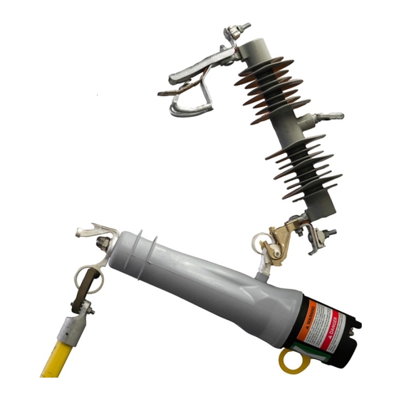
Always check the position of the vacuum interrupter by confirming the POSITION
indicator at the base of the interrupter is red before walking away. See Figure 1.
December 19, 2022
© S&C Electric Company 2022, all rights reserved
Understanding the LED Indicators and POSITION Indicator
LED Indicators
There are two LEDs on the base of the VacuFuse II interrupter. See Figure 2.
The CHARGING LED is white and indicates the VacuFuse II interrupter is harvesting
energy to close the vacuum interrupter. When the VacuFuse II interrupter is powered, the
CHARGING LED will start flashing at one flash per second as long as sufficient voltage
is present in the cutout mounting and the vacuum interrupter is open. When full charge
is achieved, the READY TO CLOSE LED will illuminate and the CHARGING LED will
continue blinking.
POSITION Indicator
The POSITION indicator is located on the base of the VacuFuse II interrupter's housing.
It contains a highly reflective visible red or green target that indicates the position of
the vacuum interrupter inside the device. The target is green when the vacuum
interrupter is in the Open position and red when the vacuum interrupter is in the
Closed position, unless the VacuFuse II interrupter was ordered with the "-J1" suffix
(red open/green closed).
Installing a VacuFuse II Interrupter into the Cutout Mounting
WARNING
Provide training to line crews on the use of both a hotstick and an extendostick
before installing or operating the VacuFuse II Self-Resetting Interrupter. The
VacuFuse II interrupter is different from other cutout-mounted devices. Failure to
properly handle a VacuFuse II interrupter with a hotstick and/or an extendostick
may lead to serious injury or death.
For instructions on how to install a cutout mounting, see the "Installing the VacuFuse II
Self-Resetting Interrupter Mounting" section of S&C Instruction Sheet 466-500.
CHARGING
LED
POSITION
LED
indicator
indicators
READY TO
CLOSE LED
Figure 1. A VacuFuse II Self-Resetting
Figure 2. A VacuFuse II Self-Resetting
Interrupter (vacuum interrupter closed).
Interrupter (vacuum interrupter open).
STEP 1.
If using an existing cutout mounting: Visually inspect the cutout mounting
for damage or excessive wear, particularly in the upper and lower contact
areas. If ANY damage is visible, replace the cutout mounting before proceeding.
DO NOT install and/or energize a VacuFuse II interrupter into a damaged
cutout mounting.
STEP 2.
Installation using insulated gloves: With the manual operating lever in the
Up position, insert the VacuFuse II interrupter into the proper cutout mounting
with gloved hands, as shown in Figure 5 on page 2.
Installation using the Talon™ Handling Tool: Attach a Talon Handling
Tool to a short hotstick. Insert the curled prong of the Talon tool into the lifting
eye of the trunnion, and raise the VacuFuse II interrupter into the mounting.
Rotate the hotstick counterclockwise 180 degrees to disengage it.
Closing the VacuFuse II Interrupter into the Cutout Mounting
Read the "Understanding the Closing Sequence" section before closing the
VacuFuse II interrupter into its cutout mounting.
Confirm the VacuFuse II interrupter is in the Open position by viewing its
STEP 1.
POSITION indicator. Place the manual operating lever in the correct position
for the closing sequence desired.
STEP 2.
Stand firmly in front of and in line with the cutout mounting. Do not operate
standing directly underneath the VacuFuse II interrupter. If using an
extendostick, stand from 6 to 10 feet (1.8 to 3.1 m) away from the pole.
STEP 3.
Insert the straight prong of a Talon tool or distribution prong into the pull-ring.
STEP 4.
Swing the VacuFuse II interrupter to within approximately 45 degrees of the
fully Closed position. See Figure 3.
STEP 5.
While firmly gripping the stick, drive the VacuFuse II interrupter closed with
POSITION
forward force. Maintain the forward force until the interrupter properly closes
indicator in
and latches into the cutout mounting.
the Open
Disengage the prong from the pull-ring, taking care to avoid pulling the
STEP 6.
(green)
VacuFuse II interrupter open.
position
45°
Figure 3. A VacuFuse II interrupter within
approximately 45 degrees of the fully
Closed position.
NOTICE
Instruction Sheet 466-501
Advertisement
Table of Contents

Related Manuals for S&C VacuFuse II


Summary of Contents for S&C VacuFuse II
- Page 1 If ANY damage is visible, replace the cutout mounting before proceeding. VacuFuse II Self-Resetting Interrupters must be installed, operated, and maintained There are two LEDs on the base of the VacuFuse II interrupter. See Figure 2. DO NOT install and/or energize a VacuFuse II interrupter into a damaged...
- Page 2 POSITION indicator at the base of the VacuFuse II interrupter displays a green target. In this case, the VacuFuse II interrupter may not be powered and cannot drop out. Refer The VacuFuse II Self-Resetting Interrupter is designed to protect distribution The VacuFuse II Self-Resetting Interrupter is designed to protect distribution to the “Troubleshooting”...
Need help?
Do you have a question about the VacuFuse II and is the answer not in the manual?
Questions and answers