Bowflex Velocore Manual
- Assembly and owner's manual (37 pages) ,
- Quick start manual (17 pages)
Advertisement
- 1 Registration
- 2 Specifications
- 3 Before Assembly
- 4 Parts
- 5 Hardware
- 6 Assembly
- 7 Installing the Shoe Clips on SPD Cycling Shoes
- 8 Before You Start
- 9 Features
-
10
Operations
- 10.1 What to Wear
- 10.2 How Often Should You Exercise
- 10.3 Mounting and Dismounting the Machine
- 10.4 Seat Adjustment
- 10.5 Foot Position/Pedal Strap Adjustment
- 10.6 Using the Shoe Clips
- 10.7 Handlebar Adjustment
- 10.8 Console Alignment
- 10.9 Locking the Flywheel for Storage
- 10.10 Initial Set-Up
- 10.11 Power-Up Mode
- 10.12 Auto Shut-Off/Sleep Mode
- 10.13 Resistance Adjustment
- 10.14 Paused/Workout Complete Mode
- 10.15 Power-Off or Restart the Machine
- 11 Maintenance
- 12 Troubleshooting
- 13 IMPORTANT SAFETY INSTRUCTIONS
- 14 Safety Warning Labels and Serial Number
- 15 Documents / Resources
Registration
If purchased in US/Canada: To register your product warranty, go to: www.bowflex.com/register or call 1 (800) 605-3369
If purchased outside US/Canada: To register your product warranty, contact your local distributor.
For details regarding product warranty or if you have questions or problems with your product, please contact your local distributor. To find your local distributor, go to: global.bowflex.com
Specifications
| Maximum User Weight | 147 kg (325 lbs.) | ||
| 16" monitor | 22" monitor | ||
| Machine Weight without Dumbbells | 67.6 kg (149 lb.) | 69.1 kg (152.3 lb.) | |
| Approx. Screen Size (measured diagonally) | 39.6 cm (15,6") | 54.6 cm (21.5") | |
| Weight of Dumbbells (supplied in U.S./Canada) | 2.7 kg (6 lbs.) | ||
| Total Surface Area (footprint) of equipment | 9290.2 cm2 (1140 in2) | ||
| Power Requirements | |||
| (Power Adapter) | Input Voltage | 100-240V AC, 50-60Hz, 1.5A | |
| Output Voltage: | 12V DC, 5A | ||
| (Arms Band - supplied in U.S./Canada) | Rechargeable | ||

Before Assembly
Select the area where you are going to set up and operate your machine. For safe operation, the location must be on a hard, level surface. We recommend an assembly area of 2.7 m x 1.8 m (108 in x 72 in). Estimated time to assemble the machine is 30-60 minutes. Allow a workout area of a minimum 2.1 m x 1.5 m (84 in x 60 in). Keep at least 0.6 m (24") along the side used to access the machine clear and at least 0.3 m (12") clear along the other side for the side to side lean mode.

NOTICE: Inspect the machine for damaged parts due to delivery. If damage is found, contact Customer Service (if inside US/Canada) or your local distributor (if outside US/Canada) for assistance.
Basic Assembly Tips
Follow these basic points when you assembly your machine:
- Read and understand the "Important Safety Instructions" before assembly.
- Collect all the pieces necessary for each assembly step.
- Using the recommended wrenches, turn the bolts and nuts to the right (clockwise) to tighten, and the left (counterclockwise) to loosen, unless instructed otherwise.
- When attaching 2 pieces, carefully lift and look through the bolt holes to help insert the bolt through the holes.
- The assembly requires 2 people.
Parts

| Item | Qty | Description | Item | Qty | Description |
| 1 | 1 | Main Assembly | 12 | 1 | Console (22" console option shown) |
| 2 | 1 | Stabilizer, Front | 13 | 1 | End Cap, Console Mast* |
| 3 | 1 | Stabilizer, Rear | 14 | 1 | Pedal, Left (L) |
| 4 | 1 | Handlebar | 15 | 1 | Pedal, Right (R) |
| 5 | 1 | Handlebar Post | 16 | 2 | Dumbbell Holder |
| 6 | 1 | Seat Stem | 17 | 2 | Water Bottle Holder |
| 7 | 1 | Seat Assembly | 18 | 1 | AC Adapter w/Cord |
| 8 | 1 | End Cap, Seat Stem* | 19 | 2 | Dumbbell |
| 9 | 3 | Adjustment Handle, Handlebar / Seat * | 20 | 2 | Shoe Clips (Cleats)* |
| 10 | 1 | Console Mast | 21 | 1 | Bluetooth Heart Rate (HR) Armband |
| 11 | 1 | Adjustable Console Mast |
*These items are in bag with Tools
Hardware
Hardware is pre-installed on the machine.
Note: Selected pieces of the pre-installed hardware have been provided as spares in the bag.
Tools

Assembly
- Attach Stabilizers to Frame
Note: The hardware (*) is pre-installed on the Stabilizers. Remove the hardware and discard the nut (a) from the end of the long screws. If a tube is pre-installed in the stabilizer bracket, remove and discard safely.
NOTICE: Leave the plastic cap (b) in place to prevent the Frame cable connector from falling down into the machine.
Make sure the hardware is fully tightened.
- Install the Handlebar to the Handlebar Post
NOTICE: Remove the AC Adapter from the Handlebar. The hardware (*) is pre-installed. After installation, make sure the hardware is fully tightened.

- Attach the Handlebar Assembly and Seat Stem to the Frame Assembly
NOTICE: Make sure the Handlebar Post Adjustment Handle is fully tightened to secure it on the Handlebar Post, and the Seat Stem Adjustment Handle is fully tightened to secure it on the Seat Stem. When fully tightened, the Adjustment Handles must point downward.
Note: To adjust the height after the handle is tightened, loosen the handle as you hold the upright post to prevent it from dropping. Move it to the desired position and tighten the handle. Pull the handle out to disengage and turn so that it points down, then release.


 Do not set the Seat Stem or Handlebar Post position higher than the stop mark (STOP) on the tube.
- Install the Seat Assembly to the Frame Assembly
NOTICE: Remove the pre-installed hardware (*) from the Seat Stem. Slide the Seat Assembly into position. Attach the Seat Stem End Cap with the hardware (*). Make sure the Seat Adjustment Handle is fully tightened to secure the Seat Assembly on the Seat Stem. When fully tightened, the Adjustment Handle must point rearward.
Note: To adjust the seat after the handle is tightened, loosen the handle. Move the seat to the desired position and tighten the handle. Pull the handle out to disengage and turn so that it points rearward, then release.

- Attach the Console Mast to the Frame Assembly
NOTICE: Leave the plastic cap (b) in place to prevent the Frame cable connector from falling down into the machine. Connect the Console Mast cable to the Frame cable. Remove the wire from the Console Mast cable and pull the connector out of the Console Mast tube. Gently pull the cable from the top of the Console Mast to remove all slack. Do not pinch or cut the cables.
Remove the pre-installed hardware (*) from the Frame. Carefully slide the Console Mast into position. Hand tighten the screws at the base of the Console Mast.

- Attach the Adjustable Console Mast to the Frame Assembly
NOTICE: Remove the pre-installed hardware (*) from the Adjustable Console Mast. Use the pull cable in the Adjustable Console Mast to route the Console Mast cable through the round hole at the base of the Adjustable Console Mast tube to the opening at the top. Attach the Adjustable Console Mast with the hardware ("). Do not pinch or cut the cables. The ease of Console rotation can be adjusted by the tightness of the pivot screw.

- Install the Console to the Frame Assembly
NOTICE: Remove the Console mast cover (12a) and pre-installed hardware(*) from the back of the Console before you connect the cables.
Route the Console cable through the Console Mount up to the opening at the top. Connect the Console cable and Console Mast cable. Do not pinch or cut the cables.


NOTICE: Push the extra wire down into the Console Mast. Reinstall the console hardware (*). Install the Console Mast End Cap (13) and Console mast cover (12a). Do not pinch or cut the cables.
Make sure the Console and Console Mast are aligned with the machine, then fully tighten the screws at the base of the Console Mast.
- Attach Pedals to Frame Assembly
Note: The Left Pedal is reverse-threaded. Be sure to attach Pedals on the proper side of the Bike. Orientation is based from a seated position on the bike. The Left Pedal has an "L", the Right Pedal an "R".
NOTICE: The Pedals MUST be installed straight into the Crank Arms by hand or the threads that secure the Pedals may strip. Start the Pedal by hand. If you feel resistance and the Pedal does not turn smoothly into the Crank Arm, make sure that the threads are aligned correctly. Be sure that the Pedal is going on straight into the Crank Arm. If the Pedal is not in-line with the opening, remove the Pedal and start again.


If the threads strip due to improper installation, then the Pedals can disengage from the bike and/or break while under usage, which can result in serious injury to the user.

With the Pedal started by several hand turns into the Crank Arm, fully tighten it with the 15 mm Wrench.
Confirm that the Pedal is fully tightened with the Wrench.
Repeat with the other Pedal.
- Attach the Dumbbell Holders to the Frame Assembly
Note: The hardware (*) is pre-installed on the Console Mast.

- Attach the Water Bottle Holders to the Frame Assembly
Note: The hardware (*) is pre-installed on the Frame.

- Attach the AC Adapter to the Frame Assembly

- Set Up Your Machine
- With the machine plugged into a functioning wall outlet, the machine will start up and the red Status LED will activate.
Note: The Console may go to sleep if it does not receive any input. Touch the screen of the Console to wake up the machine.
![]()
- The machine will activate and display the Welcome - Connect Wifi screen. Tap on Connect.
Note: A Wifi connection is required to use your Bowflex VeloCore machine. If you do not have a Wifi connection available, contact your Bowflex Representative or your local distributor immediately for further assistance. - The Console will display the list of available Wifi connections. Tap on the desired Wifi connection, and enter the password. Tap on Connect.
- The Console will test and connect to the Wifi connection.
If the Console displays an Update Available screen, tap on the Agree button. The Console will update the software. - With a Wifi connection established, tap on Back.
- Tap on Get Started.
- The Console will display the options screen. Choose Log In or Create Account. Follow the prompts to register your new fitness machine. When registration is completed, your fitness machine is now ready for use.
- The Console will display the Just for You tab. Complete the Fitness Assessment workout to unlock all workout content available to you. You can go to the Learn tab for more information about your options.
- With the machine plugged into a functioning wall outlet, the machine will start up and the red Status LED will activate.
- Final Inspection
Inspect your machine to ensure that all hardware is tight and components are properly assembled.
Be sure to record the serial number in the field provided at the front of this manual.
NOTICE: After your first few workouts, some hardware will need to be tightened again. To ensure quiet and smooth operation, make sure to tighten the indicated hardware after three workouts. Consult the Maintenance section of this manual for recommended future service intervals.- Check all of the Stabilizer fasteners to make sure they are secure.

- Tighten the Handlebar and Seat Post adjustment knobs, making sure they are not loose.

- Check the screws on the base of the Console Mast, and make sure they are fully tightened.

- Using a wrench, make sure the Pedals are tightened fully to the crank arms. Pedals should be very tight. Check weekly to ensure that they are tight.
Note: The Left Pedal is reverse-threaded.

- Check all of the Stabilizer fasteners to make sure they are secure.


Do not use or put the machine into service until the machine has been fully assembled and inspected for correct performance in accordance with the Owner's Manual.
Installing the Shoe Clips on SPD Cycling Shoes
(SPD Cycling Shoes not provided)
Note: The provided shoe Cleats fit both the right and left Pedals.
Tools needed (not included): pliers, 4 mm hex wrench
- With a pair of pliers, pull off the rubber cover to expose the cleat mounting holes on the bottom of the cycling shoe.
Note: This step may not be necessary, depending on the type of shoe.
![]()
- From the bottom of the shoe, put the anti-skid sheet in position over the cleat holes and then a cleat. Be sure the single arrow on the cleat points toward the toe of the shoe. Tighten the cleat mounting bolts (2.5 N-m).
Note: The mounting bolts must be very tight. Tighten one bolt then the other, then repeat to get them both very tight.

- The cleat has an adjustment range of 20mm front to back and 5mm left to right. Practice engaging with the Pedal and releasing, one shoe at a time. Readjust to determine the best cleat position.
![]()
- Using a 4mm hex key, fully tighten the cleat mounting bolts (5-6 N·m).
Note: For more information on how to use the shoes with the pedals, go to the "Using the Shoe Clips" section.


Before You Start
Moving and Storing the Machine
The machine may be moved by one or more persons depending on their physical abilities and capacities. Make sure that you and others are all physically fit and able to move the machine safely.
- Remove the power adapter. Remove the dumbbells, any media devices, or water bottles from the bike before moving it.
- Be sure the machine is stabilized in the upright position with the Lean Lock Knob pulled up (locked position).
- To lock the Flywheel, turn the Emergency Brake/Resistance Adjustment Knob clockwise until it encounters an increase in resistance. Then rotate the Emergency Brake/Resistance Adjustment Knob another 1/2 turn clockwise.
Tighten the Emergency Brake/Resistance Adjustment Knob as described until the Flywheel is locked before moving it.
- Use the Transport Handle to carefully lift the machine onto the transport rollers.

- Push the machine into position.
- Carefully lower the machine into position.
NOTICE: Be careful when you move the machine. Abrupt motions can affect the computer operation.

For safe storage of the machine, remove the power adapter and place in a secure location. Be sure the machine is stabilized in the upright position with the Lean Lock Knob pulled up (locked position). Tighten the Brake/Resistance Adjustment Knob as described until the Flywheel is locked. Place the machine in a secure location away from children and pets.
Leveling the Machine

The machine needs to be leveled if your workout area is uneven. Levelers are found on each side of the front stabilizer. Lift the stabilizer slightly to take the weight off the adjuster, then turn the stabilizer foot to adjust.
Do not adjust the levelers to such a height that they detach or unscrew from the machine. Injury to you or damage to the machine can occur.
Make sure the machine is level and stable before you exercise.
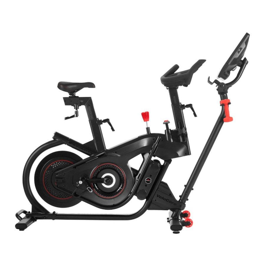
Features

| A | Adjustment Handle, Seat Slider | N | Lean Pivot |
| B | Seat Slider | O | Power Inlet |
| C | Seat | P | Front Stabilizer |
| D | Adjustment Handle, Seat Post | Q | Transport Wheel |
| E | Emergency Brake/Resistance Adjustment Knob | R | Leveler |
| F | Brake Assembly | S | Rear Stabilizer |
| G | Lean Lock Knob | T | Transport Handle |
| H | Handlebar Assembly | U | Flywheel |
| I | Console (22" option shown) | V | Pedal w/Foot Restraint and Shoe Cleat |
| J | Adjustable Console Mast | W | Shoe Clips (Cleats) |
| K | Dumbbell Rack (Dumbbells only supplied with U.S./Canada machines) | X | USB Charging Port |
| L | Adjustment Handle, Handlebar Post | Y | Bluetooth Connectivity (not shown) |
| M | Water Bottle Holder | Z | Bluetooth Heart Rate (HR) Receiver (not shown) |

Use the values calculated or measured by the machine's computer for reference purposes only. The heart rate displayed is an approximation and should be used for reference only. Over exercising may result in serious injury or death. If you feel faint stop exercising immediately.
Emergency Stop

To stop the pedals immediately, push down hard on the Emergency Brake/Resistance Adjustment Knob.
This bike cannot stop the Pedals independently of the Flywheel. Reduce the pace to slow the Flywheel and Pedals to a stop. Do not dismount the bike until the Pedals have come to a complete stop. Be aware that the moving Pedals can strike the backs of the legs.
Resistance Adjustment
Turn the Emergency Brake/Resistance Adjustment Knob to adjust the resistance level. Clockwise will increase the value, counter-clockwise will decrease the value.
Lean Mode

To unlock the leaning mode, push the button all the way down with an open hand. To lock the bike in the stationary mode, pull up on the button until it clicks. Take a moment to practice unlocking and locking the lean mode.
NOTICE: The bike must be upright in order for the Lean Lock Knob to engage in the locked position. Do not attempt to set the Knob in a partially locked position.
Console

You can access your JRNY membership through the console of this Bowflex machine. With a JRNY membership, you receive guided workouts adapted to your capabilities, conveniently displayed on your console, and friendly virtual voice coaching designed to support you on your journey to long-term fitness success.
A Wifi connection is required to use your Bowflex machine. If you do not have a Wifi connection available, contact your Bowflex Representative immediately for further assistance.
Note: Your Console may not look exactly as the provided images. These images are to be used only as a guide to your machine. Users without a JRNY membership may find some content disabled or locked. All coaching, custom workouts, Explore The World videos and trainer led workout videos are only available through a Wifi connection with a JRNY membership. Available workouts can be found on the Programs tab, Explore the World tab, Workouts, and the JUST FOR YOU tab.
Console Display
The Console Display home page includes convenient access to basic features, such as manual and standard workout program. Everything can be controlled with a simple touch of the Display. Just touch the Display to make a selection, start a workout, or to simply wake up the Console.
Note: The buttons on the back of the Console are for factory reset and recovery. They are not intended for customer use. The Power/Sleep button turns off the backlight on the console, so it appears off but the electronics are still on.

Status LED
The Status LED shows if the Console is activated and starting up/operating correctly (LED is on), or if the Console is experiencing an error (LED blinks 3 times). To reset the Console during an error, disconnect the power to the machine for 30 seconds and reconnect it.
* A JRNY membership is required for the JRNY experience - see www.bowflex.com/jrny for details. For United States and Canada customers, you can obtain a JRNY membership by calling 800-269-4126 or visiting www.bowflex.com/jrny. Where available (including the United States), you can also obtain a JRNY membership by downloading the JRNY app onto your phone or tablet and signing up within the downloaded app. JRNY memberships may not be available in all countries.
JUST FOR YOU tab
After logging in, the Just For You tab is the starting, or home, screen for your machine. Guided adaptive workout options* and educational videos are presented here, encouraging you on your fitness journey.
Recommended Workouts
Recommended workouts are based on your current fitness level, past workouts and selected time and difficulty settings. Tap on a Suggested Workout card to see an expanded description.
Note: Users without a JRNY membership will see only the Time selection slider.
PROGRAMS tab
The Programs tab provides access to all guided adaptive workouts (with or without virtual voice coaching)*, along with the standard workouts programs.
EXPLORE THE WORLD tab
The Explore The World videos* allow you to ride through virtual outdoor destinations.
VIDEOS tab
The Videos tab provides workouts led by fitness trainers*, categorized by difficulty and organized by time.
FAVORITES tab
Quick access to your favorite content. To add an option to your Favorites tab, tap on the heart icon in the upper-right corner.
LEARN tab
Provides educational videos and key feature information about fitness.
WORKOUTS
The Workouts tab centrally collects all of the available workouts and educational videos.
JOURNAL
Displays the workout summary (Overview), Past Workouts, and Awards for the selected User Profile.
PROFILE
View and edit your User Profile details, settings, and JRNY membership information.

Console Display with Lean and Core Engagement
Metrics Bar
Time
Counts in minutes and seconds the total time of your workout (e.g. 15:42 minutes).
Interval
During an Interval workout, the Intervals display show the currently active Interval and the total number of Intervals for the workout. Each Interval has a Sprint and a Recover workout segment.
Distance
The Distance display shows your workout distance in miles or kilometers based on the user setting.
Calories
The Calories display counts your total calories.
Burn Rate
The Burn Rate display shows the level of calories being burned per minute. This rate is a function of Intensity, which is the current level of RPM (pedal speed) and resistance level. As either of those values increase, the Burn Rate will increase.
Heart Rate
Remote Heart Rate (HR) Monitor required. The Heart Rate display shows your heart beats per minute. The heart icon will flash when acquiring the rate. With a stable reading, the icon will be shown as solid.
The heart rate displayed is an approximation and should be used for reference only.
Cadence
Cadence shows your current pedal speed in revolutions per minute (RPM).
Resistance
Resistance shows the resistance level set by the Resistance Knob.
Workout Profile
The Workout Profile is a visualization of the workout (showing intensity). The higher the profile line, the more intense the workout.
Interval Time
The Goal display shows the total workout time or the total calories for a non-interval workout. During an Interval workout, the Goal display counts down the time until the end of the workout. This display will be blank during a Manual workout. When the goal is time based, the clock icon is displayed. Use the Subtraction (-) or Addition (+) buttons to modify the Goal display.
Burn Rate/Benefit Zone Meter
The Burn Rate / Benefit Zone Meter shows the level of calories being burned per minute. This rate is a function of Intensity, which is the current level of RPM (pedal speed) and resistance level. As either of those values increase, the Burn Rate will increase.
Burn Rate Target range
The Burn Rate Target range is based on the selected User Profile. A range of Burn Rate segments are activated during an Interval workout. The intensity of the range is based on the Workout Profile display.
Note: For a more exact calorie burn rate and suggested target range, be sure to complete a Fitness Assessment workout and keep the User Profile current.
The Target Range is a suggested workout level, and should only be followed if your physical fitness level allows.
During an Interval workout, the SPRINT range will be the red segments, and the RECOVER range will be the blue segments.
Maximum Burn Rate marker
The Maximum Burn Rate marker is an indicator that shows the highest rate of calorie burn achieved during the current workout.
Benefit Zone meter
The Benefit Zone meter will be displayed during Standard and Manual workouts, with three suggested zones: Fat Burn, Endurance, and Performance.
USB Charging
If a USB Device is attached to the USB Port, the Port will attempt to charge the Device. The power supplied from the USB Port may not be enough to operate the Device and charge it at the same time.
Bluetooth Heart Rate Enabled
Your fitness machine is equipped to be able to receive a signal from a Bluetooth Heart Rate (HR) Monitor. Follow the instructions provided with your Bluetooth HR monitor.
If you have a pacemaker or other implanted electronic device, consult your doctor before using a Bluetooth strap or other Bluetooth heart rate monitor.
Note: Be sure to remove the protective cover (if provided) from the Heart Rate Sensor before use.
Bluetooth Heart Rate Armband
A Bluetooth Heart Rate Armband is provided with your fitness machine. To use the Bluetooth Heart Rate Armband, follow the instructions that were included with the Armband.
If you have a pacemaker or other implanted electronic device, consult your doctor before using a Bluetooth armband or other Bluetooth heart rate monitor.
Note: Be sure to remove the protective cover (if provided) from the Heart Rate Sensor before use.
- Put the Bluetooth Heart Rate Armband onto the upper portion of your forearm.
- Confirm that Bluetooth wireless connection is active on the machine. If the Bluetooth icon is blue, then it is active.
If the icon is red, then Bluetooth wireless connection must be activated. To activate Bluetooth wireless connection:- Tap the Bluetooth icon.
- Tap "Manage Bluetooth"
- Slide the option from "OFF" to "ON".
- Tap Back to exit.
- When ready to exercise, start your workout.
- Push the On/Off LED button on the Heart Rate Armband. Be sure to only push the On/Off LED button once.
- During your workout, the Heart Rate Armband may take up to 60 seconds to connect. When connected, the Bluetooth Heart Rate Device icon will be displayed along with your heart rate.
Note: The Armband can only be connected once to an active workout. If the On/Off LED button is pushed after being connected, the workout must be restarted.
![]()

Use the values calculated or measured by the machine's computer for reference purposes only.
Heart Rate Calculations
Your maximum heart rate usually decreases from 220 Beats Per Minute (BPM) in childhood to approximately 160 BPM by age 60. This fall in heart rate is usually linear, decreasing by approximately one BPM for each year. There is no indication that training influences the decrease in maximum heart rate. Individuals of the same age could have different maximum heart rates. It is more accurate to find this value by completing a stress test than by using an age related formula.
Your at-rest heart rate is influenced by endurance training. The typical adult has an at-rest heart rate of approximately 72 BPM, whereas highly trained runners may have readings of 40 BPM or lower.
The Heart Rate table is an estimate of what Heart Rate Zone (HRZ) is effective to burn fat and improve your cardiovascular system. Physical conditions vary, therefore your individual HRZ could be several beats higher or lower than what is shown.
The most efficient procedure to burn fat during exercise is to start at a slow pace and gradually increase your intensity until your heart rate reaches between 60 - 85% of your maximum heart rate. Continue at that pace, keeping your heart rate in that target zone for over 20 minutes. The longer you maintain your target heart rate, the more fat your body will burn.
The graph is a brief guideline, describing the generally suggested target heart rates based on age. As noted above, your optimal target rate may be higher or lower. Consult your physician for your individual target heart rate zone.
Note: As with all exercises and fitness regimens, always use your best judgment when you increase your exercise time or intensity.

Speakers
To play audio through the speakers on your machine, open an App on the Console and allow it to stream audio.
Note: Your machine is also able to receive and play audio across a Bluetooth connection from your device or stream audio from the machine to your Bluetooth device (such as Bluetooth headphones). Bluetooth audio can only be streamed in one direction (in or out) at a time.
Shoe Clips
Foot pedals that are equipped for cycling shoes with cleats provide secure footing on the exercise bike. The shoe cleats provided fit both the right and left Pedals.
Prior to use, make sure you understand the operation of the engagement / release mechanism for the pedals and cleats (shoes).
Keep cleats and bindings clear of dirt and debris to ensure engagement and release.
Check the cleats periodically for wear. When the cleats are worn, replace them. Replace the cleat when it becomes difficult to release, or starts to release with much less effort than when it was in new condition.
Pedals and cleats are SPD Compatible. They fit any shoe size with the correct cleat mounts: shoes with "Standard 2-Hole MTB SPD Cleat Mounts" (MTB SPD = Mountain Bike Shimano Pedaling Dynamics).
Operations
What to Wear
Wear rubber-soled athletic shoes or cycling shoes with cleats. You will need the appropriate clothes for exercise that allow you to move freely.
How Often Should You Exercise
Consult a physician before you start an exercise program. Stop exercising if you feel pain or tightness in your chest, become short of breath, or feel faint. Contact your doctor before you use the machine again. Use the values calculated or measured by the machine's computer for reference purposes only. The heart rate displayed is an approximation and should be used for reference purposes only.
- 3 times a week for 20 minutes each day.
- Schedule workouts in advance and try to follow the schedule.
Mounting and Dismounting the Machine
Before mounting or dismounting the machine, be sure it is stabilized in the upright position with the Lean Lock Knob pulled up (locked position).
Care should be used when mounting or dismounting the machine.
Before mounting or dismounting the machine, be sure it is stabilized in the upright position with the Lean Lock Knob completely pulled up (locked position). If the Lean Lock mechanism is not engaged, the bike may become unbalanced and fall, which can cause injury or damage to the equipment.
Seat Adjustment
Correct seat placement encourages exercise efficiency and comfort, while reducing the risk of injury.
When you adjust the seat, use the shoes that you plan to wear for riding.
- Standing next to the bike, raise/lower the Seat so that it is level with the top of your hip bone.
- Sit on the bike. With the hips level, place the ball of the foot on the Pedal at the bottom of the pedal stroke (6 o'clock). The leg should be slightly bent at the knee (approx. 20 degrees).
- If your leg is too straight or your foot cannot touch the Pedal, you need to move the seat downward. If your leg is bent too much, you need to move the seat upward.
Step off the machine before you adjust the seat.
- Loosen the Seat Post Adjustment Handle on the Seat Post as you hold the upright post to prevent it from dropping. Adjust the seat to the desired height.
![]()

Do not lift the Seat post above the "STOP" mark on the Seat Post.
- Tighten the Seat Post Adjustment Handle to secure the Seat Post. Be sure that the handle is fully tightened. Pull the handle out to disengage and turn so that it points down, then release.
- While seated, rotate the Pedals so they are level (a 3 o'clock/9 o'clock position). In this position, be sure the front knee is aligned over or slightly behind the pedal axle.
- To move the seat closer to, or away from the console, loosen the Seat Slider Adjustment Handle. Slide the seat to the desired position and fully tighten the handle. Pull the handle down to disengage and turn so that it points rearward, then release.
Note: If the handle cannot turn due to contact with another part, pull the handle, turn and push it back in to reposition it. Continue turning as needed.
Be sure the Seat is straight and level. To adjust the Seat:
Step off the machine before you adjust the seat.
- Using a 14 mm wrench, loosen the nuts on the Seat bracket.
![]()
- If the Seat is not straight, turn the Seat bracket on the post. If the Seat is not level, adjust the tilt.
- Hold the Seat in position and fully tighten both nuts to secure the Seat.

Foot Position/Pedal Strap Adjustment
Foot pedals with straps provide secure footing to the exercise bike.
- Put the ball of each foot in the Foot Restraint on the Pedals.
- Fasten the strap over the shoe.
![]()
- Repeat for the other foot.

Be sure toes and knees point directly forward to ensure maximum Pedal efficiency. Pedal straps can be left in position for subsequent workouts.
NOTICE: If you choose to replace the Pedals with your own, then make sure to follow that pedal manufacturer's installation specifications.
Using the Shoe Clips
Foot pedals that are equipped for cycling shoes with cleats provide secure footing on the exercise bike. Be sure to turn the Pedals so that the Foot Restraint is under the Pedal.
Prior to use, make sure you understand the operation of the engagement/ release mechanism for the pedals and cleats (shoes).
Keep cleats and bindings clear of dirt and debris to ensure engagement and release.
Check the cleats periodically for wear. When the cleats are worn, replace them. Replace the cleat when it becomes difficult to release, or starts to release with much less effort than when it was in new condition.
Pedals and cleats are SPD Compatible. They fit any shoe size with the correct cleat mounts: shoes with "Standard 2-Hole MTB SPD Cleat Mounts" (MTB SPD = Mountain Bike Shimano Pedaling Dynamics).
- Be sure that the arrow on top of the Pedal points forward.
- Push the cleat down and forward to engage the Pedal.
![]()
- Repeat for the other foot.
- Practice engaging and disengaging from the Pedals before starting your workout.
![]()


To disengage (release) the cleats from the pedals, push the heels outward and lift.
If the body weight of a user is very low, the user may have difficulty with operation of the engagement/release mechanism in the Pedals. It may be necessary to decrease the retention force of the mechanism. To adjust the retention:
- Locate the opening in the rear of the Pedal for access to the adjustment bolt. It is between the 2 screws that attach the Foot Restraint to the Pedal.
- Use a 3mm hex wrench to turn the adjustment bolt. To decrease the retention, turn it left (counterclockwise). To increase the retention, turn it right (clockwise).
![]()

Handlebar Adjustment
The ideal position should allow a slight bend in the elbows and your shoulders to fall into a relaxed position.
To adjust the handlebar position:

- Loosen the Handlebar Post Adjustment Handle on the Handlebar Post as you hold the upright post to prevent it from dropping. Adjust the Handlebar to the desired height.
Do not lift the Handlebar Post above the "STOP" mark on the Handlebar Post.
- Tighten the Handlebar Post Adjustment Handle to secure the Handlebar. Be sure that the handle is fully tightened. Pull the handle out to disengage and turn so that it points down, then release.
Note: If the handle cannot turn due to contact with another part, pull the handle, turn and push it back in to reposition it. Continue turning as needed.
Console Alignment
The Console should be aligned so that the position provides the optimum screen display. If all three of the following alignments are necessary, it is recommended to do them in the order listed below. Adjust the angle of the Console/Adjustable Console Mast after alignment.
If the Console does not face the Seat directly:
- Loosen the 4 screws at the base of the Console Mast and rotate the Console Mast until the Console is square with the bike.
![]()
- Tightly secure the screws.

If the Console is not centered horizontally:
- Remove the Console mast cover from the back of the Console. It may also be necessary to remove the Console Mast End Cap.
- Loosen the 4 Console screws (indicated) and adjust the Console horizontally.
![]()
- Tightly secure the screws.

If the Console is not level:
- Remove the Console mast cover (if not already removed).
- Loosen the 2 screws on the Adjustable Console Mast (indicated) and tilt the Console to level it.
![]()
- Tightly secure the screws.

Adjust the Console/Adjustable Console Mast to the desired viewing angle.
Locking the Flywheel for Storage
When the machine is not in use, be sure to lock the Flywheel with the Emergency Brake/Resistance Adjustment Knob. To lock the Flywheel, turn the Emergency Brake/Resistance Adjustment Knob clockwise until it encounters an increase in resistance. Then rotate the Emergency Brake/Resistance Adjustment Knob another 1/2 turn clockwise. The Flywheel is now locked. The flywheel should be locked for storage of the machine.
For safe storage of the machine, remove the power supply and place in a secure location. Be sure the machine is stabilized in the upright position with the Lean Lock Knob completely pulled up (locked position). Tighten the Brake/Resistance Adjustment Knob as described until the Flywheel is locked. Place the machine in a secure location away from children and pets.
With the Flywheel locked, the level of resistance will be out of the range of operation displayed by the Console. Do not use the machine with the level of resistance outside of the 0% - 100% range. This will damage the ability to quickly stop the Flywheel during an emergency, and the effectiveness of securing the bike for storage. Turn the Emergency Brake/Resistance Adjustment Knob until the LEVEL displayed on the Console is less than 100%. The resistance is now in the designed range of operation for the bike.
Initial Set-Up
- Plug in the machine to a functioning wall outlet. The machine will start up, and the red Status LED will activate.
Note: The Console may go to sleep if it does not receive any input. Touch the screen of the Console to wake up the machine. - The machine will activate and display the Welcome - Connect Wifi screen. Tap on Connect.
Note: A Wifi connection is required to use your Bowflex VeloCore machine. If you do not have a Wifi connection available, contact your Bowflex Representative or your local distributor immediately for further assistance. - The Console will display the list of available Wifi connections. Tap on the desired Wifi connection, and enter the password. Tap on Connect.
- The Console will test and connect to the Wifi connection.
If the Console displays an Update Available screen, tap on the Agree button. The Console will update the software. - With a Wifi connection established, tap on Back.
- Tap on Get Started.
- The Console will display the options screen. Choose Log In or Create Account. Follow the prompts to register your new fitness machine. When registration is completed, your fitness machine is now ready for use.
- The Console will display the Just for You tab. Complete the Fitness Assessment workout to unlock all workout content available to you. You can go to the Learn tab for more information about your options.
Power-Up Mode
The Console will enter Power-Up / Home Tab if it is plugged into a power source, the Console display is touched, or if it receives a signal from the RPM sensor as a result of pedaling the machine.
Auto Shut-Off/Sleep Mode
If the Console does not receive any input in approximately 5 minutes, it will automatically shut off. The LCD display is off while in Sleep Mode. Note: The Console does not have an On/Off switch.
Resistance Adjustment
To increase the resistance and workload, turn the Resistance Adjustment Knob clockwise. To reduce the resistance, turn the Resistance Adjustment Knob counter-clockwise. The range of movement of the Resistance Adjustment Knob is 0% to slightly past the 100% level of resistance (locked Flywheel). Do not turn the Resistance Adjustment Knob past the range of movement. If turned past the range of movement, damage to the machine may occur.
Paused/Workout Complete Mode
- To Pause a workout, stop pedaling during the workout.
Note: The Console will automatically pause if there is no RPM signal for 5 seconds, or if you tap the screen and tap the Pause button.
When paused, the Console will display the Play and Stop buttons. - To continue the workout, begin pedaling or tap the Play button.
To end the workout before completing it, tap Stop. - After the workout, the Console will display the Workout Complete values (Total Time, Total Intervals, Total Calories, Average Sprint Burn Rate, Average Heart Rate, Average RPM, and Average Resistance).
- Tap Continue.
- The Console will go to the Overview of the Latest Workout of the JOURNAL tab.
Power-Off or Restart the Machine
Note: When active, the Bowflex VeloCore machine checks for software updates and installs them. If the machine is de-activated for a period of time, it may try to install updates when restarted.
To turn off the machine:
- Log off.
- Disconnect the power cord from the wall outlet.
To restart the machine:
- Plug in the machine to a functioning wall outlet. The machine will start up, and the red Status LED will activate.
Maintenance
Read all maintenance instructions fully before you start any repair work. In some conditions, an assistant is required to do the necessary tasks.
Equipment must be regularly examined for damage and repairs. The owner is responsible to make sure that regular maintenance is done. Worn or damaged components must be repaired or replaced immediately. Only manufacturer supplied components can be used to maintain and repair the equipment.
If at any time the Warning labels become loose, unreadable or dislodged, replace the labels. If purchased in US/Canada, contact Customer Service for replacement labels. If purchased outside US/Canada, contact your local distributor for them.
Disconnect all power to the machine before you service it.
Daily:
Before each use, examine the exercise machine for loose, broken, damaged, or worn parts. Do not use if found in this condition. Repair or replace all parts at the first sign of wear or damage. Make sure adjustment knobs are tight. Tighten as necessary. Check the Pedals and tighten as necessary. After each workout, use a damp cloth to wipe your machine and Console free of moisture.
NOTICE: If necessary, only use a mild dish soap with a soft cloth to clean the Console. Do not clean with a petroleum based solvent, automotive cleaner, or any product that contains ammonia. Do not clean the Console in direct sunlight or at high temperatures. Be sure to keep the Console free of moisture.
Weekly:
Check pedals and crank arms and tighten as necessary. Make sure all bolts and screws are tight. Tighten as necessary.
Since this machine operates with a fixed gear, do not back, or reverse, pedal. Doing so may loosen the Pedals, which could result in damage to the machine and/or injury to the user. Never operate this machine with loose Pedals.
Clean the machine to remove any dust, dirt, or grime from the surfaces.
Check for smooth seat operation.
Note: Do not use petroleum based products.
Monthly or after 20 hours:
Check the drive belt tension and adjust if necessary.
Checking the Drive Belt Tension
To check the Drive Belt tension, the bike needs to be operated. Set the resistance at a medium to high level. Get the pedals rotating at about 20 RPM. Then suddenly increase the RPM to your maximum ability. If the pedals move normally with no slipping, the tension is correct. If the Pedals slip, the belt needs to be adjusted.
An "Adjust the Belt Tension" procedure can be found in the Service Manual.
Maintenance Parts


Troubleshooting
| Condition/Problem | Things to Check | Solution |
| No display/partial display/unit will not turn on | Check electrical (wall) outlet | Make sure unit is plugged into a functioning wall outlet. |
| Check connection at front of unit | Connection should be secure and undamaged. Makes ure the adapter is fully plugged into the power inlet connector. Replace adapter or connection at unit if either are damaged. | |
| Check data cable integrity | Be sure cable is connected securely and oriented properly. Small latch on connector should line up and snap into place. | |
| Check console display for damage | Check for visual sign that console display is cracked or otherwise damaged. Replace Console if damaged. | |
| If the above steps do not resolve the problem, contact Customer Service (if inside US/Canada) or your local distributor (if outside US/Canada) | ||
| Speed displayed is always "0"/stuck in pause mode | Data cable | Make sure the data cable is connected to the Console from the main frame assembly. |
| Speed Sensor | Make sure the data cable is connected to the Speed Sensor. | |
| No Speed/RPM reading | Check data cable integrity | All wires in cable should be intact. If any are cut or pinched, replace cable. |
| Check data cable connections/orientation | Be sure cable is connected securely and oriented properly. Small latch on connector should line up and snap into place. | |
| Check Speed Sensor Assembly | Speed Sensor Assembly should be connected to data cable. Realign sensor if necessary. Replace if there is any damage to the sensor or the connecting wire. | |
| Unit operates but Bluetooth Heart Rate (HR) not displayed | Bluetooth Heart Rate Sensing Device (Armband provided with U.S./Canada machines) | Make sure device is directly against skin and device is on. |
| Bluetooth Heart Rate Sensing Device Batteries | If device has replaceable batteries, install new batteries. Make sure batteries are changed, if applicable. | |
| Interference | Try moving unit away from sources of interference (TV, Microwave, etc). | |
| Connected to previous user | The Console may be still connected to the previous user. Push Connect Bluetooth button to disconnect from them/connect to your Heart Rate Sensing Device | |
| Console shuts off (enters sleep mode) while in use | Check electrical (wall) outlet | Make sure unit is plugged into a functioning wall outlet |
| Check connection at front of unit | Connection should be secure and undamaged. Replace adapter or connection at unit if either are damaged. | |
| Check data cable integrity | All wires in the cable should be intact. If any are cut or pinched, replace cable. | |
| Check data cable connections/orientation | Be sure cable is connected securely and oriented properly. Small latch on connector should line up and snap into place. | |
| Reset machine | Unplug unit from electrical outlet for 3 minutes. Reconnect to outlet. | |
| Check Speed Sensor | Speed sensor should be connected to data cable. Replace if there is any damage to the sensor or the connecting wire. | |
| Contact Customer Service (if inside US/Canada) or your local distributor (if outside US/Canada) | ||
| Unit rocks/does not sit level | Check level adjustment | Levelers may be turned to level machine. |
| Check surface under unit | Adjustment may not be able to compensate for extremely uneven surfaces. Move machine to level area. | |
| Pedals loose/unit difficult to pedal/ Pedals seem to skip or slip with a sudden increase in rpm | Check pedal to crank connection | Pedal should be tightened securely to crank arm. Be sure connection is not cross-threaded. Do not use if pedal is not fully tightened. |
| Check crank arm to axle connection | Crank arm should be tightened securely to axle. | |
| Check drive belt tension | Refer to the "Adjust the Belt Tension" procedure. Contact Customer Service (if inside US/Canada) or your local distributor (if outside US/Canada) | |
| Clicking sound when pedaling | Check pedal to crank connection | Remove pedals. Make sure there is not debris on threads, and reinstall the pedals. |
| Seat post movement | Check adjustment handle | Be sure the adjustment handle is securely tightened |
| Handlebar post movement | Check adjustment handle | Be sure the adjustment handle is securely tightened |
| Click, tick or knocking sound | Check for loose hardware | Tightly secure all hardware. |
| Bike will not lean | Check Lean Lock Knob | Be sure knob is pushed completely down (unlocked position) |
| Bike will not lock in Stationary mode | Check Lean Lock Knob | Be sure bike is upright. Pull the knob completely up until you hear a click. |
| If the Lean Knob mechanism does not click, contact Customer Service (if inside US/Canada) or your local distributor (if outside US/Canada) | ||
| Noise/rattling from Lockout assembly | Check Lean Lock Knob | Be sure knob is pushed completely down (unlocked position) |
| Left and Right lean force is not the same | Check bumper tension | Refer to the "Adjust the Lean Tension" procedure in the service manual. Contact Customer Service (if inside US/Canada) or your local distributer (if outside US/Canada) |
| Console continuously displays a video of machine features | Console is in demonstration mode | Tap on the upper-right corner of the console display ten times. Tap on "Demo mode app", and then tap on the "De-activate Demo mode" option. |
IMPORTANT SAFETY INSTRUCTIONS
When using an electrical appliance, basic precautions should always be followed, including the following:
This icon means a potentially hazardous situation which, if not avoided, could result in death or serious injury.
Obey the following warnings:
Read and understand all warnings on this machine.
Carefully read and understand the Assembly instructions. Read and understand the complete Manual. Keep the Manual for future reference.
- Keep bystanders and children away from the product you are assembling at all times.
- Do not connect power supply to the machine until instructed to do so.
![shock hazard]() To reduce the risk of electrical shock or unattended/unsupervised usage, always unplug the AC Adapter from the wall outlet and the machine and wait 5 minutes before cleaning, maintaining or repairing the machine. Place the AC Adapter in a secure location.
To reduce the risk of electrical shock or unattended/unsupervised usage, always unplug the AC Adapter from the wall outlet and the machine and wait 5 minutes before cleaning, maintaining or repairing the machine. Place the AC Adapter in a secure location.- Do not assemble this machine outdoors or in a wet or moist location.
- Make sure assembly is done in an appropriate work space away from foot traffic and exposure to bystanders.
- Some components of the machine can be heavy or awkward. Use a second person when doing the assembly steps involving these parts. Do not do steps that involve heavy lifting or awkward movements on your own.
- Set up this machine on a solid, level, horizontal surface.
- Do not try to change the design or functionality of this machine. This could compromise the safety of this machine and will void the warranty.
- If replacement parts are necessary use only genuine replacement parts and hardware supplied by Nautilus. Failure to use genuine replacement parts can cause a risk to users, keep the machine from operating correctly and void the warranty.
- Do not use or put the machine into service until the machine has been fully assembled and inspected for correct performance in accordance with the Manual.
- Read and understand the complete Manual supplied with this machine before first use. Keep the Manual for future reference. Do all assembly steps in the sequence given. Incorrect assembly can lead to injury or incorrect function.
- Connect this machine to a properly grounded or earthed outlet only.
- Keep the AC Adapter away from heat sources and hot surfaces.
- SAVE THESE INSTRUCTIONS.
 To reduce the risk of electrical shock or unattended/unsupervised usage, always unplug the AC Adapter from the wall outlet and the machine and wait 5 minutes before cleaning, maintaining or repairing the machine. Place the AC Adapter in a secure location.
 Before using this equipment, obey the following warnings:
Read and understand the complete Manual. Keep the Manual for future reference.
Read and understand all warnings on this machine. If at any time the Warning stickers become loose, unreadable or dislodged, replace the labels. If purchased in US/Canada, contact Customer Service for replacement labels. If purchased outside US/Canada, contact your local distributor for them.
- Children must not be let on or near to this machine. Moving parts and other features of the machine can be dangerous to children.
- Not intended for use by anyone under 14 years of age. Individuals between 14 and 17 years of age must be supervised when using this machine.
- Consult a physician before you start an exercise program. Stop exercising if you feel pain or tightness in your chest, become short or breath, or feel faint. Contact your doctor before you use the machine again. Use the values calculated or measured by the machine's computer for reference purposes only.
- Before each use, examine the machine for damage to power cord, power receptacle, loose parts or signs of wear. Do not use if found in this condition. Monitor the Seat, Pedals, and Crank Arms closely. If purchased in US/Canada, contact Customer Service for repair information. If purchased outside US/Canada, contact your local distributor for repair information.
- This appliance should only be used with the power supply unit provided, or a replacement power supply unit supplied from Nautilus, Inc.
- Maximum user weight limit: 147 kg (325 lbs.). Do not use if you are over this weight.
- This machine is for home use only. Do not place or use the machine in a commercial or institutional setting. This includes gyms, corporations, work places, clubs, fitness centers and any public or private entity that has a machine for use by its members, customers, employees or affiliates.
- Do not wear loose clothing or jewelry. This machine contains moving parts. Do not put fingers or other objects into moving parts of the exercise equipment.
- Always wear rubber soled athletic shoes or cycling shoes with cleats when you use this machine. Do not use the machine with bare feet or only wearing socks.
- Set up and operate this machine on a solid, level, horizontal surface.
- Do not step off the machine until the Pedals have fully stopped.
- Make the Pedals stable before you step on them. Ensure the bike is in its stationary mode by pulling up on the Lean Lock Knob and use caution when you step on and off the machine.
- Disconnect all power before servicing this machine.
- Do not operate this machine outdoors or in moist or wet locations. Keep the Pedals clean and dry.
- Keep at least 0.6 m (24") along the side used to access the machine clear and at least 0.3 m (12") clear along the other side for the side to side lean mode. Keep at least 0.6 m (24") to the rear of the machine clear. This is the recommended safe distance for access and passage around and emergency dismounts from the machine. Keep third parties out of this space when machine is in use.
- Do not over exert yourself during exercise. Operate the machine in the manner described in this manual.
- Perform all regular and periodic maintenance procedures recommended in the Owner's Manual.
- Do not drop or put objects into any opening of the machine.
- Correctly adjust and safely engage all Positional Adjustment Devices. Make sure that the Adjustment Devices do not hit the user.
- Exercise on this machine requires coordination and balance. Be sure to anticipate that changes in speed and resistance level can occur during workouts, and be attentive in order to avoid loss of balance and possible injury.
- For safe storage of the machine, remove the power supply and place in a secure location. Tighten the Brake/Resistance Adjustment Knob as described until the Flywheel is locked. Place the machine in a secure location away from children and pets.
- Since this machine operates with a fixed gear, do not back, or reverse, pedal. Doing so may loosen the Pedals, which could result in damage to the machine and/or injury to the user. Never operate this machine with loose Pedals.
- This appliance is not intended for use by persons (including children) with reduced physical, sensory or mental capabilities, or lack of experience and knowledge, unless they have been given supervision or instruction concerning use of the appliance by a person responsible for their safety.
- This bike cannot stop the Pedals independently of the Flywheel. Reduce the pace to slow the Flywheel and Pedals to a stop. Do not dismount the bike until the Pedals have come to a complete stop. Be aware that the moving Pedals can strike the backs of the legs.
- Children should be supervised to ensure that they do not play with the appliance.
- SAVE THESE INSTRUCTIONS.
Safety Warning Labels and Serial Number

(Label is available in English and French Canadian only.)
For assembly video, please visit:
www.bowflex.com/getting-started.html

Workout with Other Fitness Apps
This fitness machine has integrated Bluetooth connectivity which allows it to work with a number of fitness apps. Four our latest list of supported apps, please visit:
www.nautilus.com/partners
Nautilus, Inc. 5415 Centerpoint Parkway, Groveport, OH 43125 USA, www.NautilusInc.com - Customer Service: North America (800) 605-3369, csnls@nautilus.com | Nautilus (Shanghai) Fitness Equipments Co, Ltd, Room 1701 & 1702, 1018 Changning Road, Changning District, Shanghai, China 200042, www.nautilus.cn - 86 21 6116 9668 | outside U.S. www.nautilusinternational.com
Documents / Resources
References
Product Registration | BowFlex
JRNY Digital Fitness Platform
Getting Started & Assembly Videos | BowFlex
JohnsonHealthTech
BowFlex Home Page | BowFlex
Download manual
Here you can download full pdf version of manual, it may contain additional safety instructions, warranty information, FCC rules, etc.
Advertisement


Need help?
Do you have a question about the Velocore and is the answer not in the manual?
Questions and answers