Table of Contents
Troubleshooting

Related Manuals for Emerson DCX S


Summary of Contents for Emerson DCX S
- Page 1 Original Instructions 100-412-183 - REV. 13 DCX S Power Supply O p e r a t i n g M a n u a l Branson Ultrasonics Corporation 41 Eagle Road Danbury, CT 06813-1961 USA (203) 796-0400 http://www.bransonultrasonics.com...
- Page 2 Manual Change Information At Branson, we strive to maintain our position as the leader in ultrasonics plastics joining, metal welding, cleaning and related technologies by continually improving our circuits and components in our equipment. These improvements are incorporated as soon as they are developed and thoroughly tested.
- Page 3 Foreword Congratulations on your choice of a Branson Ultrasonics Corporation system! The Branson DCX S Power Supply system is process equipment for the joining of plastic parts using ultrasonic energy. It is the newest generation of product using this sophisticated technology for a variety of customer applications. This Operating Manual is part of the documentation set for this system, and should be kept with the equipment.
- Page 4 100-412-183 REV. 13...
-
Page 5: Table Of Contents
Table Of Contents Chapter 1:Safety and Support Safety Requirements and Warnings ........2 General Precautions . - Page 6 Chapter 8:Maintenance General Maintenance Considerations ....... . . 112 Preventive Maintenance......... . 114 Calibration .
- Page 7 Figure 2.1 The DCX S Power Supply (Horizontal) ....... . .15 Figure 2.2...
- Page 8 Chapter 8:Maintenance Figure 8.1 Reconditioning Stack Mating Surfaces ....... . 116 Figure 8.2 Interconnect Diagram, Power Supply .
- Page 9 DCX S Power Supply System Cables ........31...
- Page 10 DCX S Power Supply System Cables ....... . . 121...
-
Page 11: Chapter 1:Safety And Support
Chapter 1: Safety and Support Safety Requirements and Warnings ......2 General Precautions ........5 How to Contact Branson . -
Page 12: Safety Requirements And Warnings
Safety Requirements and Warnings This chapter contains an explanation of the different Safety Notice symbols and icons found both in this manual and on the product itself and provides additional safety information for ultrasonic welding. This chapter also describes how to contact Branson for assistance. -
Page 13: Figure 1.1 Safety-Related Labels Found On The Dcx S Power Supply (Horizontal)
1.1.2 Symbols Found on the Product The DCX S Power Supply has several safety-related labels on it to indicate the presence of hazardous voltages inside the unit. Figure 1.1 Safety-related Labels Found on the DCX S Power Supply (Horizontal) 100-412-183 REV. 13... -
Page 14: Figure 1.2 Safety-Related Labels Found On The Dcx S Power Supply (Vertical)
Figure 1.2 Safety-related Labels found on the DCX S Power Supply (Vertical) 100-412-183 REV. 13... -
Page 15: General Precautions
General Precautions Take the following precautions before servicing the power supply: • Be sure the power switch is in the off position before making any electrical connections • To prevent the possibility of an electrical shock, always plug the power supply into a grounded power source •... - Page 16 1.2.1 Intended Use of the System The DCX S Power Supply and components are designed to be used as part of an ultrasonic welding system. These are designed for a wide variety of welding or processing applications. 1.2.2 Emissions When being processed, certain plastic materials can emit toxic fumes, gases or other emissions that can be hazardous to the operator’s health.
-
Page 17: How To Contact Branson
How to Contact Branson Branson is here to help you. We appreciate your business and are interested in helping you successfully use our products. To contact Branson for help, use the following telephone numbers, or contact the office nearest you. 1.3.1 Authorized Service Center (North America) Table 1.1... -
Page 18: Table 1.3 Authorized Service Centers (Asia)
Pacific Co. Ltd. Fax: 852-2341-2716 Tong Hong Kong Office info@emerson.com Kowloon, Hong Kong Branson Ultrasonics 8/35, Marol Co-Op Industrial Div. of Emerson Electric Estate Tel: 91-22-2850-5570 Co. P. Ltd. “Ajanta M.V. Road, Andheri (East) Fax: 91-22-2850-8681 House” Mumbai 400 059, India... - Page 19 Name Address Tel/Fax Number No. 20, Jalan Rajawali 3, Branson Ultrasonics Puchong Jaya Industrial Park Tel: 603-8076-8608 Div. of Emerson Elec (M) Sdn Bhd. Batu 8, Jalang Puchong Fax: 603-8076-8302 Malaysia 47170 Puchong, Selangor Malaysia Emerson Building 104 Laguna Blvd.
-
Page 20: Table 1.4 Authorized Service Centers (Europe)
Fax: 420-374-625-617 1 Rue des Pyrenees Silic 404 Branson Ultrasons Tel: 33-1-4180-2550 94573 Rungis Cedex France Fax: 33-1-4687-8729 France Niederlassung der EMERSON Tel: 49 (0)6074/497-0 Technologies GmbH & Co. Branson Ultraschall Tel: 49 (0)6074/497-784 European Headquarters Waldstraße 53-55 Fax: 49 (0)6074/497-199... - Page 21 Table 1.4 Authorized Service Centers (Europe) Name Address Tel/Fax Number Sonifers: Case Postale 1031 Tel: 41-22-304-8340 Bransonics: Chemin du Branson Ultrasonics S.A. Faubourg-de-Cruseilles 9 Tel: 41-58-611-1222 Switzerland CH 1227, Carouge, Fax: 41-22-304-8359 Switzerland 158 Edinburgh Avenue Branson Ultrasonics Tel: 44-1753-756675 Slough, Berkshire United Kingdom Fax: 44-1753-551270...
- Page 22 100-412-183 REV. 13...
-
Page 23: Chapter 2:Introduction
Chapter 2: Introduction Models Covered ......... 14 Compatibility with other Branson Products . -
Page 24: Models Covered
Models Covered This manual covers all models of the DCX S Power Supply. Table 2.1 Models Covered In This Manual Frequency Power Model Horizontal 101-132-1792 1250 W Vertical 101-132-1801 Horizontal 101-132-1793 20 kHz 2500 W Vertical 101-132-1802 Horizontal 101-132-1795 4000 W... -
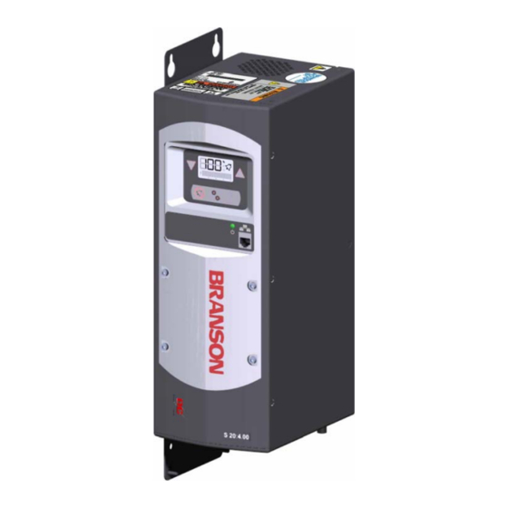
Page 25: Figure 2.1 The Dcx S Power Supply (Horizontal)
2.1.1 Overview of these Models Figure 2.1 The DCX S Power Supply (Horizontal) Figure 2.2 The DCX S Power Supply (Vertical) 100-412-183 REV. 13... - Page 26 The following documentation is available in electronic format for the DCX S Power Supply • DCX S Power Supply Instruction Manual (100-412-183) • DCX S Power Supply Quick Start Guide (100-412-185) • DCX S Power Supply Web Page Interface Instruction Manual (100-412-187) 100-412-183 REV. 13...
-
Page 27: Compatibility With Other Branson Products
CS-30S CS-30C CR-40S 40 kHz / 400 W CR-40C 40 kHz / 800 W NOTICE Special adaptor cables are available to connect to MS-style converters (CR20 and 4TR). See Table 8.8 DCX S Power Supply System Cables. 100-412-183 REV. 13... -
Page 28: Features
• Login ID Numbers: Allows for keeping track of user access to the DCX S Power Supply Web Page Interface • Ramp Starting: The starting of the DCX S Power Supply and horn is done at a rate that helps reduce electrical and mechanical stress on the system. The horn start rate may be adjusted for some tough-to-start applications •... - Page 29 2.3.3 The Actuator does not provide actuator control functions, and does not interface DCX S Power Supply with actuator signals. 2.3.4 Converter/Booster/Horn Assembly The Converter The ultrasonic electrical energy from the power supply is applied to the converter (sometimes called the transducer). This transforms the high frequency electrical oscillations into mechanical vibrations at the same frequency as the electrical oscillations.
-
Page 30: Controls And Indicators
Lights when the power supply is connected to main power indicator and the power switch is on. Use the Ethernet Service port to connect to the DCX S Power Supply Web Page Interface. Ethernet For detailed information on using the web page interface... -
Page 31: Table 2.4 Lcd Description
Figure 2.4 LCD Description Table 2.4 LCD Description Item Name Function Displays the power supply amplitude setting, a register Numeric Display number, or a register value. Sonics Active Indicates ultrasonics is running. Indicator Shows the true percentage of ultrasonic power during a weld cycle. -
Page 32: Figure 2.5 Dcx S Power Supply Back Panel (Horizontal)
Provides the necessary input/output signals to interface User I/O with user automation or control interfaces. For detailed Connector information on interfacing with the DCX S Power Supply refer to Chapter 5: Installation and Setup. SHV connector for RF cable, which provides ultrasonic RF Connector energy to the converter. -
Page 33: Welding Systems
• Cutting and sealing thermoplastic fabric and film • Staking, spot welding, swaging, and degating thermoplastic parts • Other ultrasonic processing applications DCX S Power Supply weld systems typically consist of a power supply operated with a fixed converter-booster-horn stack. 100-412-183 REV. 13... -
Page 34: Glossary Of Terms
Glossary of Terms The following terminology may be encountered when using or operating a DCX S Power Supply ultrasonic welding system: Actuator: The unit which houses the converter/booster/horn stack assembly in a rigid mounting, allowing the stack to move up and down, either mechanically or pneumatically, applying force to the part at a user-adjustable force and velocity. - Page 35 Joint: The weld surfaces. Parameter: A unique factor or element which affects the welding operation in a particular mode. Parameter Range: Valid range of parameters accepted for a particular setup. Power Supply: The electronic instrument in an ultrasonic assembly system which changes conventional 50/60 Hz electrical power into high frequency electrical power at 20 kHz, 30 kHz or 40 kHz.
- Page 36 100-412-183 REV. 13...
-
Page 37: Chapter 3:Delivery And Handling
Chapter 3: Delivery and Handling Shipping and Handling ........28 Receiving . -
Page 38: Shipping And Handling
3.1.1 Environmental Specifications The DCX S Power Supply is an electronic unit that converts line voltage to ultrasonic energy and responds to user input for regulating the weld process. Its internal components are sensitive to static discharge, and many of its components can be harmed if the unit is dropped, shipped under improper conditions, or otherwise mishandled. -
Page 39: Receiving
Receiving The DCX S Power Supply is a sensitive electronic device. Many of its components can be harmed if the unit is dropped or otherwise mishandled. Scope of Delivery Branson equipment is carefully checked and packed before dispatch. It is recommended, however, that you follow the procedure below upon receiving your DCX S Power Supply. -
Page 40: Unpacking The Power Supply
Unpacking the Power Supply NOTICE If there are any visible signs of damage to the shipping containers or the product, or you later discover hidden damage, NOTIFY YOUR CARRIER IMMEDIATELY. Save the packing material. The power supply is fully assembled. It is shipped in a sturdy cardboard box. Some additional items are shipped in the box with the power supply. -
Page 41: Take Inventory Of Small Parts
The RF cable connects the power supply to the converter. For automated systems you will also need a user I/O cable to monitor and control the power supply. Check your invoice for cable types and cable lengths. Table 3.5 DCX S Power Supply System Cables Description 100-240-383 Cable, RF 8 ft (2.5 m) 100-240-384 Cable, RF 15 ft (4.5 m) -
Page 42: Returning Equipment
Returning Equipment If you are returning equipment to Branson Ultrasonic Corporation, please call your Customer Service Representative to receive approval to return the goods. Refer to How to Contact Branson. 100-412-183 REV. 13... -
Page 43: Chapter 4:Technical Specifications
Chapter 4: Technical Specifications Technical Specifications ........34 Physical Description . -
Page 44: Table 4.1 Environmental Specifications
-13° F to +131° F (-25° C to +55° C) Humidity Maximum 95%, non-condensing IP Rating 4.1.2 Electrical Specifications The following tables list input voltage and current requirements for the DCX S Power Supply. Table 4.2 Electrical Input Operating Voltages Power Supply Rating Input Operating Voltage 200 V to 230 V Nominal (180 V Min.* to 253 V Max.), 50 Hz... -
Page 45: Table 4.3 Input Current And Circuit Breaker Specifications
Table 4.3 Input Current and Circuit Breaker Specifications Model Power Current Rating 400 W 3 A Max. @ 200 V / 10 A Breaker 40 kHz 800 W 5 A Max. @ 200 V / 10 A Breaker Table 4.4 Continuous Duty Max. -
Page 46: Physical Description
Physical Description This section describes the physical dimensions of the DCX S Power Supply NOTICE Dimensions are nominal. Table 4.5 Dimension and Weight of DCX S Power Supply Size Width Height Depth Weight 14” 5.5” Small (Benchtop) 356 mm 132 mm 7.4”... -
Page 47: Declaration Of Conformity
Declaration of Conformity Figure 4.1 Declaration of Conformity 100-412-183 REV. 13... -
Page 48: Standard Modules And Components
Standard Modules and Components The following sections describe the DCX S Power Supply internal circuits. 4.4.1 System Block Diagram The block diagram for the DCX S Power Supply is shown below. Figure 4.2 System Block Diagram 4.4.2 Circuit Descriptions The DCX S Power Supply contains the following sub-assemblies: •... - Page 49 DCP-I Control Board The DCP-I Control Board controls the following functions of the power supply: • Responding to start and stop signals • Responding to alarm and reset signals • Responding to user input • Controlling and monitoring ultrasonics • Providing information for the Front Panel LCD •...
- Page 50 100-412-183 REV. 13...
-
Page 51: Chapter 5:Installation And Setup
Chapter 5: Installation and Setup About Installation........42 Installation Requirements . -
Page 52: About Installation
International safety-related labels are found on the power supply. Those that are of importance during installation of the system are identified in Figure 1.1 Safety-related Labels Found on the DCX S Power Supply (Horizontal) Figure 1.2 Safety-related Labels found on the DCX S Power Supply (Vertical). -
Page 53: Installation Requirements
All dimensions are approximate and may vary slightly: Figure 5.1 DCX S Power Supply Benchtop Dimensional Drawing Figure 5.2 DCX S Power Supply Vertical Mount Dimensional Drawing (400 W, 750 W and 800 W) Figure 5.3 DCX S Power Supply Vertical Mount Dimensional Drawing (1.25 kW and 1.5 Figure 5.4 DCX S Power Supply Vertical Mount Dimensional Drawing (2.5 kW and 4 kW) - Page 54 Figure 5.1 DCX S Power Supply Benchtop Dimensional Drawing 100-412-183 REV. 13...
- Page 55 Figure 5.2 DCX S Power Supply Vertical Mount Dimensional Drawing (400 W, 750 W and 800 W) 5.22 in (132.6 mm) 4.5 in 7.75 in (114 mm) (196.8 mm) 3.5 in (89 mm) 3.0 in (76 mm) recommended fan clearance 17.38 in...
-
Page 56: Figure 5.3 Dcx S Power Supply Vertical Mount Dimensional Drawing (1.25 Kw And 1.5 Kw)
Figure 5.3 DCX S Power Supply Vertical Mount Dimensional Drawing (1.25 kW and 1.5 kW) 5.22 in (132.6 mm) 4.5 in 9.0 in (114 mm) (229 mm) 3.5 in (89 mm) 3.0 in (76 mm) recommended fan clearance 15.75 in 17.38 in... -
Page 57: Figure 5.4 Dcx S Power Supply Vertical Mount Dimensional Drawing (2.5 Kw And 4 Kw)
Figure 5.4 DCX S Power Supply Vertical Mount Dimensional Drawing (2.5 kW and 4 kW) 5.22 in (132.6 mm) 4.5 in 11.0 in (114 mm) (279 mm) 3.5 in (89 mm) 3.0 in (76 mm) recommended fan clearance 15.75 in 17.38 in... -
Page 58: Table 5.1 Environmental Requirements
5.2.2 Environmental Requirements Verify the DCX S Power Supply is operated in an environment that meets the temperature and humidity requirements indicated in Table 5.1 Environmental Requirements. Table 5.1 Environmental Requirements Environmental Condition Acceptable Range Ambient Operating Temperature +41° F to +104° F (+5° C to +40° C) -
Page 59: Installation Steps
Installation Steps WARNING High Voltage Hazard To prevent the possibility of an electrical shock: • Ensure the power source is disconnected before beginning work on line connections • Ensure the power switch on the back of the unit is in the OFF position before making any electrical connections •... - Page 60 5.3.2 Horizontal (Benchtop) Mounting The Horizontal DCX S Power Supply is designed to be placed on a workbench (rubber feet on bottom) within cable-length limits of the stack. It has one fan which draws cooling air from the left side to the right side, which must be free from obstruction. The controls on the front of the power supply should be accessible and readable for setup changes.
-
Page 61: Figure 5.5 Lcd Viewing Angle
Mounting Considerations In addition to the considerations mentioned above, the LCD’s viewing angle should be taken into account when selecting a location for your DCX S Power Supply. The LCD is designed to be viewed from the top. Please refer to Figure 5.5 LCD Viewing Angle... -
Page 62: Figure 5.6 Dcx S Power Supply Connections (Horizontal Model)
5.3.5 Electrical Connections Figure 5.6 DCX S Power Supply Connections (Horizontal Model) Table 5.3 DCX S Power Supply Connections (Horizontal Model) Item Description RF Connector Ground Screw User I/O Connector Cable Ties Circuit Breaker (On/Off Switch) 100-412-183 REV. 13... -
Page 63: Figure 5.7 Dcx S Power Supply Connections (Vertical Model)
Figure 5.7 DCX S Power Supply Connections (Vertical Model) Table 5.4 DCX S Power Supply Connections (Vertical Model) Item Description Circuit Breaker (On/Off Switch) Ground Screw User I/O Connector RF Connector Cable Ties NOTICE Connector is shown rotated. 100-412-183 REV. 13... - Page 64 Ensure all unused wires are properly isolated. Failure to do so may result in a power supply malfunction. Digital I/O functions can be configured to either active-high or active-low using the DCX S Power Supply Web Page Interface. Tables Table 5.6 Available Digital Input Functions Table 5.9 Available Analog Output Functions...
-
Page 65: Figure 5.8 User I/O Cable Identification And Wire Color Diagram
Figure 5.8 User I/O Cable Identification and Wire Color Diagram User I/O Cable Stripped Jacket one end, HD-26 male connector other end (cable length as ordered) Wire Color Diagram Two Colors = Insulator/Stripe Three Colors = Insulator/Stripe/Dot Item Description Part number Insulation Stripe 100-412-183 REV. -
Page 66: Table 5.5 User I/O Cable Pin Assignments
Input 10%, 12 mA Digital in 3 Input Digital in 4 Functions +24 V Supplied 24 V +/-10%, from DCX S Power 24 V Source 250 mA Max Supply Digital out 1 Table Wht/Blk 0 V to 24 V +/-... -
Page 67: Table 5.6 Available Digital Input Functions
Activates ultrasonic energy at the currently set amplitude. NOTICE DCX S Power Supply must be in ready mode before External Start. External Start WARNING When using 0 V to activate ultrasonics (External Start signal), it is recommended to assign one input as Cable Detect to prevent sonics from activating if 24 V is lost by accident. -
Page 68: Table 5.7 Available Digital Output Functions
5.3.9 Available Digital Output Functions Table 5.7 Available Digital Output Functions Function Description General Alarm Indicates an alarm occurred. Overload Alarm Indicates an overload alarm has occurred. Ready Indicates the system is ready. Seek/Scan Out Indicates either a seek or a horn scan is in progress. Sonics Active Indicates sonics are active. -
Page 69: Table 5.8 Available Analog Input Functions
5.3.10 Available Analog Input Functions Table 5.8 Available Analog Input Functions Function Description Valid Range Controls the amplitude of ultrasonic 1 V to 10 V* Amplitude In energy that will be delivered by the power (10% to 100%) supply. Controls the frequency offset to the power supply operating frequency. -
Page 70: Table 5.9 Available Analog Output Functions
5.3.11 Available Analog Output Functions Table 5.9 Available Analog Output Functions Function Description Valid Range 0 V to 10 V Provides a 0 V to 10 V output signal Amplitude Out proportional to amplitude (0% to 100%). (0% to 100%) Provides a 0 V to 10 V output signal 0 V to 10 V Power Out... -
Page 71: Table 5.10 Default User I/O Connector Pin Assignments
I/O Type Values Apply +24 VDC to run cycle External Start Input Digital NOTICE DCX S Power Supply must be in ready mode before External Start. External Seek Input Digital Apply +24 VDC to perform a seek External Reset Input Digital... -
Page 72: Figure 5.9 Typical Digital I/O Wiring Examples
5.3.13 Typical Digital I/O Wiring Examples Figure 5.9 Typical Digital I/O Wiring Examples 5.3.14 Typical Analog I/O Wiring Examples Figure 5.10 Typical Analog I/O Wiring Examples 100-412-183 REV. 13... -
Page 73: Figure 5.11 Rf Cable Connection
5.3.15 Output Power (RF Cable) Connection Ultrasonic energy is delivered to the SHV connector on the power supply, which is then transmitted to the converter via the RF cable. The RF connector position depends on the power supply configuration. For Horizontal models it is located on the rear panel of the power supply. -
Page 74: Table 5.12 Input Power Connection
Use three properly sized wires (No. 12 gage, 2.5 mm or according to local standards) to connect the line 1, line 2, and ground to the connector block as shown on Figure 5.6 DCX S Power Supply Connections (Horizontal Model). Choose wires according to the current rating as specified in Table 5.2 Input... - Page 75 Table 5.12 Input Power Connection Step Action Connect the converter-booster-horn stack to the power supply using the RF cable. See 5.3.15 Output Power (RF Cable) Connection. Ensure the power switch on the back of the unit is in the OFF position. Plug the connector block back into the power supply.
-
Page 76: Power Supply Configuration
• Latching: In this mode the DCX S Power Supply requires alarm conditions to be reset before a new weld cycle can begin. To reset alarm conditions while in this mode, either press the front panel Reset key or send an External Reset signal using the user I/O connector •... -
Page 77: Assembling The Acoustic Stack
Assembling the Acoustic Stack CAUTION General Warning The following procedure must be performed by a setup person. If necessary, secure the largest portion of a square or rectangular horn in a soft jawed vise. NEVER attempt to assemble or remove a horn by holding the converter housing or the booster clamp ring in a vise. -
Page 78: Figure 5.12 Assembling The Acoustic Stack
Figure 5.12 Assembling the Acoustic Stack Table 5.13 Acoustic Stack Description Item Description Converter Booster Spanner (provided) Horn See stack assembly procedure Vise Jaw protectors (aluminum or soft metal) Vise Table 5.14 Stack Torque Values Frequency Torque 20 kHz 220 in·lb (24.85 N·m) 30 kHz 185 in·lb (21 N·m) 40 kHz... -
Page 79: Table 5.15 Tools
Table 5.15 Tools Tool EDP Number 20 kHz, and 30 kHz Torque Wrench Kit 101-063-787 40 kHz Torque Wrench 101-063-618 20 kHz Spanner Wrench 101-118-039 30 kHz Spanner Wrench 201-118-033 40 kHz Spanner Wrench 201-118-024 Silicone Grease 101-053-002 Mylar Plastic Film Washers (20 kHz) 100-063-357 Mylar Plastic Film Washers (30 kHz) 100-063-632... -
Page 80: Table 5.16 20 Khz System
5.5.1 For a 20 kHz System Table 5.16 20 kHz System Step Action Ensure that the mating surfaces of the converter, booster, and horn are clean, and that the threaded holes are free of foreign material. Install a single Mylar plastic film washer (matching the size of the washer to the stud) to each interface. -
Page 81: Figure 5.13 Connecting Tip To Horn
Use the spanner wrench and an open-end wrench (refer to Figure 5.13 Connecting Tip to Horn) and tighten to the following torque tip specifications: Figure 5.13 Connecting Tip to Horn Table 5.19 Tip to Horn Values Tip Thread Torque 1/4 - 28 110 in·lbs (12.42 N·m) 3/8 - 24 180 in·lbs (20.33 N·m) -
Page 82: Converter Cooling
Converter Cooling Converter performance and reliability can be adversely affected if the converter ceramics are subjected to temperatures above 140º F (60º C). The converter front driver temperature should not exceed 122º F (50º C). To prolong converter life and maintain a high degree of system reliability, the converter should be cooled with clean, dry, compressed air, particularly if your application calls for continuous ultrasonic operation. -
Page 83: Table 5.21 Converter Cooling Procedure
If converter cooling is required, use the following steps: Table 5.21 Converter Cooling Procedure Step Action Start with a 50 psi (345 kPa) air source or higher from a 0.06 in (1.5 mm) I.D. orifice Perform a run of welding operations. Immediately after completing the welding run, check the converter temperature. -
Page 84: Testing The Installation
Testing the Installation To test the power supply follow the procedure described in 7.7 Ultrasonics Test Procedure Chapter 7: Operation. 100-412-183 REV. 13... -
Page 85: Still Need Help
Still Need Help? Branson is pleased that you chose our product and we are here for you! If you need parts or technical assistance with your DCX S Power Supply system, call your local Branson representative. Please refer 1.3 How to Contact Branson for a list of Branson key contacts. - Page 86 100-412-183 REV. 13...
- Page 87 Chapter 6: Converters and Boosters Converters and Boosters ........78 100-412-183 REV.
-
Page 88: 6:Converters And Boosters
Converters and Boosters A variety of converters and boosters available for use with the DCX S Power Supply are illustrated in the following pages. WARNING High Voltage Hazard To avoid the possibility of electrical shock. Converters need to be properly grounded. -
Page 89: Figure 6.1 20 Khz Ch-20S Converter Dimensions
Figure 6.1 20 kHz CH-20S Converter Dimensions Table 6.1 20 kHz CH-20S Converter Dimensions Item Description Air inlet Ground stud SHV connector Grip area 100-412-183 REV. 13... -
Page 90: Figure 6.2 20 Khz Booster Dimensions
Figure 6.2 20 kHz Booster Dimensions Table 6.2 20 kHz Booster Dimensions Item Description 1/2 - 20 x 1 - 1/4 stud (Ti boosters) 1/2 - 20 x 1 - 1/2 stud (Al boosters) Grip Ring Diameter Variable Varies with tuning and gain * These dimensions do not vary. -
Page 91: Figure 6.3 20 Khz Converter/Booster/Horn, Typical Dimensions
Figure 6.3 20 kHz Converter/Booster/Horn, Typical Dimensions Table 6.3 20 kHz Converter/Booster/Horn, Typical Dimensions Item Description Converter Booster One-half wavelength horn Recommended clamping area Booster front end diameter will vary with amplitude * Overall horn length can vary beyond these typical dimensions depending on the application. 100-412-183 REV. -
Page 92: Figure 6.4 30 Khz Converter Dimensions
Figure 6.4 30 kHz Converter Dimensions Table 6.4 30 kHz Converter Dimensions Item Description Air inlet SHV connector Ground stud Grip area CR-30S and CH-30S are dimensionally identical, and differ only in their respective cooling feature. CR-30S has flow through cooling, and CH-30S has closed loop cooling (air circulates in the converter and returns to its source). -
Page 93: Figure 6.5 30 Khz Booster Dimensions
Figure 6.5 30 kHz Booster Dimensions Table 6.5 30 kHz Booster Dimensions Item Description 3/8 - 24 x 1 - 1/4 stud Grip Ring Diameter Variable Varies with tuning and gain * These dimensions do not vary. 100-412-183 REV. 13... -
Page 94: Figure 6.6 30 Khz Converter/Booster/Horn, Typical Dimensions
Figure 6.6 30 kHz Converter/Booster/Horn, Typical Dimensions Table 6.6 30 kHz Converter/Booster/Horn, Typical Dimensions Item Description Converter Booster One-half wavelength horn Recommended clamping area Booster front end diameter will vary with amplitude * Overall horn length can vary beyond these typical dimensions depending on the application. 100-412-183 REV. -
Page 95: Figure 6.7 40 Khz, 4Tr Converter Dimensions
Figure 6.7 40 kHz, 4TR Converter Dimensions Table 6.7 40 kHz, 4TR Converter Dimensions Item Description Ground stud SHV connector Grip area 100-412-183 REV. 13... -
Page 96: Figure 6.8 40 Khz Booster Dimensions
Figure 6.8 40 kHz Booster Dimensions Table 6.8 40 kHz Booster Dimensions Item Description M8 x 1 - 1/4 stud (Ti boosters) M8 x 1 - 1/2 stud (Al boosters) Grip ring diameter Variable Varies with tuning and gain 100-412-183 REV. 13... -
Page 97: Figure 6.9 40 Khz Converter/Booster/Horn, Typical Dimensions
Figure 6.9 40 kHz Converter/Booster/Horn, Typical Dimensions Table 6.9 40 kHz Converter/Booster/Horn, Typical Dimensions Item Description Converter Booster One-half wavelength horn Recommended clamping area Booster front end diameter will vary with amplitude * Overall horn length can vary beyond these typical dimensions depending on the application. ** Dimension varies with tuning and gain. - Page 98 6.1.1 Component Functional Description Ultrasonic Stack Converter The converter is mounted in the customer's automation as part of the ultrasonic stack. The ultrasonic electrical energy from the power supply is applied to the converter (sometimes called the transducer). This transforms the high frequency electrical oscillations into mechanical vibrations at the same frequency as the electrical oscillations.
-
Page 99: Chapter 7:Operation
Chapter 7: Operation Activating Ultrasonic Power ....... . 90 Setting the Amplitude........91 Resetting the Power Supply Alarms . -
Page 100: Activating Ultrasonic Power
Ultrasonic power remains On until you turn off the power supply or the External Start signal. For default user I/O assignment see 5.3.6 User I/O Connections For information on configuring the power supply user I/O refer to your DCX S Power Supply Web Page Interface Instruction Manual (100-412-187). 100-412-183 REV. 13... -
Page 101: Setting The Amplitude
Setting the Amplitude 7.2.1 Using the Front Panel Controls At power up the DCX S Power Supply will display the last amplitude setting on the LCD. Figure 7.1 LCD at Power Up Table 7.1 Setting the Amplitude Using the Front Panel Controls... -
Page 102: Figure 7.2 Lcd When In External Amplitude Control Mode
The ultrasonic amplitude can be controlled using one of the two analog input pins on the user I/O connector (pins 17 and 18). For information on configuring the power supply user I/O refer to your DCX S Power Supply Web Page Interface Instruction Manual (100-412- 187). -
Page 103: Resetting The Power Supply Alarms
Remove and re-apply the start signal. NOTICE Alarm circuitry requires at least 20 ms before restarting ultrasonic power. For more information on interfacing the DCX S Power Supply using the user I/O connections refer to 5.3.6 User I/O Connections Chapter 5: Installation and Setup. -
Page 104: Configuring The Power Supply Registers
Configuring the Power Supply Registers At power up the DCX S Power Supply will display the last amplitude setting, this is indicated by the percentage icon (%) on the LCD. Refer to Figure 7.1 LCD at Power Table 7.3 Steps to configure the Power Supply Registers... - Page 105 Table 7.3 Steps to configure the Power Supply Registers Step Action Reference Press and release the Up or Down arrow keys to enter the desired value at 1 increments. Press and hold down the Up and Down arrow keys and the value will auto increment at 1 increments every quarter of a second.
-
Page 106: Table 7.4 Power Supply Registers
7.4.1 Power Supply Registers Table 7.4 Power Supply Registers Read Min. Max. Default Register Description Only Value Value Value 0 -100 Unused LCD Software version Bar graph identification after weld complete (power) (freq) (power) Latching Alarms (reset required) 0 = OFF 1 = ON 0 = OFF External amplitude control - user... - Page 107 Table 7.4 Power Supply Registers Read Min. Max. Default Register Description Only Value Value Value Subnet Mask for IP address 4 DHCP Setting (0 = Server; 1 = Client; 2 = Static IP; 3 = Restore Registers 116 - 127 to default values) Amplitude Reserved...
-
Page 108: Lcd Bar Graph
LCD Bar Graph While ultrasonic power is active the LCD will always display the power value on the 20- segment LCD bar graph as a percentage of the maximum output power. At the end of a weld or test cycle, the bar graph is factory set to represent the cycle’s peak power as a percentage of the maximum output power. -
Page 109: Table 7.6 Frequency Bar-Graph Interpretation - 20 Khz (50 Hz Segment)
7.5.2 Frequency Bar-Graph Interpretation The actual frequency depends on the power supply’s operating frequency. Use Table 7.6 Table 7.8 below to interpret frequency bar graph readings. NOTICE If there is a test overload or an external memory reset signal is received, then the 50% segment will be displayed and blinking. -
Page 110: Table 7.8 Frequency Bar-Graph Interpretation - 40 Khz (100 Hz/Segment)
Table 7.8 Frequency Bar-Graph Interpretation - 40 kHz (100 Hz/Segment) 40 kHz (50 Hz/Segment) Table 7.9 Frequency Bar Graph Interpretation Examples Description Reference In this example the bar is located in the 11th segment. If the power supply is a 20 kHz unit, the stack is running in the frequency range of 19,975 Hz to 20,024 Hz. -
Page 111: Web
7.6.1 System Requirements To connect to the DCX S Power Supply Web Page Interface you will need a PC running a Windows® operating system with an Internet Explorer® web browser software (versions 7 and up). - Page 112 7. Right click on Local Area Connection and select Properties to bring up the Networking tab. 8. Highlight Internet Protocol Version 4 (TCP/IPv4) from the list and click on Properties. 100-412-183 REV. 13...
- Page 113 11.Open the Internet Explorer web browser (version 7 and up). 12.In the address bar type the following address: http://192.168.10.100. Press Enter. 13.This will bring up the DCX S Power Supply Web Page Interface. 14.Enter a user ID number (any number up to 9 digits long).
- Page 114 7.6.4 Point to Point Connection (Windows XP) 1. To connect directly to the DCX S Power Supply Web Page Interface using a PC with Windows XP® operating system, complete the following steps: 2. Connect the power supply to a computer via the Ethernet port.
- Page 115 14.Enter a user ID number (any number up to 9 digits long). 7.6.5 Using the Web Page Interface For complete instructions detailing the web page interface consult the DCX S Power Supply Web Page Interface Instruction Manual (100-412-187). 100-412-183 REV. 13...
-
Page 116: Ultrasonics Test Procedure
Ultrasonics Test Procedure The Ultrasonics Test function measures ultrasonic power dissipated by the ultrasonic stack with no load. Autotune with Memory (ATM) function ensures that the power supply does not require any manual adjustments. The ultrasonics test procedure involves an automatic matching of the frequency of the power supply to the frequency of the converter-booster- horn stack. -
Page 117: Figure 7.3 Test Connections
7.7.1 Using the Front Panel Controls Table 7.10 Power Supply Ultrasonic Test Procedure (Front Panel) Step Action Reference Turn on the power supply. The front panel Power LED and LCD turn on. Press the test key for 1-2 seconds, then release. -
Page 118: Table 7.12 Power Supply Ultrasonic Test Procedure (Web
Table 7.12 Power Supply Ultrasonic Test Procedure (Web Page Interface) Step Action Turn on the power supply. The front panel Power LED should turn on. Connect to the DCX S Power Supply Web Page Interface. See 7.6.2 Connecting to the Web Page Interface. - Page 119 Table 7.12 Power Supply Ultrasonic Test Procedure (Web Page Interface) Step Action Go to the P/S Diagnostics tab. Press the Start Test button to start the test. Sonics will become active and the button will change to Stop Test. Press the button again to stop the test.
- Page 120 100-412-183 REV. 13...
-
Page 121: Chapter 8:Maintenance
Chapter 8: Maintenance General Maintenance Considerations ......112 Preventive Maintenance ........114 Calibration . -
Page 122: General Maintenance Considerations
General Maintenance Considerations WARNING High Voltage Hazard Power supplies produce high voltage. To avoid the possibility of an electrical shock, you should always power down your system prior to repairing any portion of it. CAUTION General Warning When performing maintenance on the welder, make sure that no other automated systems are active. - Page 123 NOTICE To prevent circuit damage from electrostatic discharge, always service the power supply on a static-dissipative surface, while wearing a properly grounded wrist strap. 100-412-183 REV. 13...
-
Page 124: Preventive Maintenance
Preventive Maintenance The following preventive measures help assure long term operation of your DCX S Power Supply equipment. 8.2.1 Periodically Clean the Equipment NOTICE Use only anti-static vacuum cleaners to prevent damage from electrostatic discharge to your power supply. Air is continuously drawn into the power supply. Periodically disconnect the unit from power, remove the cover and vacuum out any accumulated dust and debris. -
Page 125: Table 8.1 Stack Reconditioning Procedure
8.2.2 Recondition the Stack (Converter, Booster, and Horn) NOTICE Never clean the converter-booster-horn stack mating surfaces by using a buffing wheel or by filing. Welding system components work most efficiently when the converter-booster-horn stack mating surfaces are flat, in solid contact, and free from fretting corrosion. Poor contact between mating surfaces wastes power output, makes tuning difficult, increases noise and heat, and may cause damage to the converter. -
Page 126: Figure 8.1 Reconditioning Stack Mating Surfaces
Table 8.1 Stack Reconditioning Procedure Step Action Rotate the part another 120 degrees to the next spanner-wrench hole, and repeat the lapping procedure in step 6. Re-examine the mating surface. If necessary, repeat steps 2-5 until you remove most of the contaminant. Remember, this should not require more than two to three complete rotations for an aluminum horn or booster;... -
Page 127: Table 8.3 Stack Torque Values
8.2.2.1 Stack Torque Values Table 8.3 Stack Torque Values Frequency Torque 20 kHz 220 in·lb (24.85 N·m) 30 kHz 185 in·lb (21 N·m) 40 kHz 95 in·lb (10.73 N·m) For a 20 kHz System Table 8.4 Stack Reassembly for a 20 kHz System Step Action Clean the mating surfaces of the converter, booster, and horn. -
Page 128: Table 8.5 Stack Reassembly For A 30 Khz System
For a 30 kHz System Table 8.5 Stack Reassembly for a 30 kHz System Step Action Clean the mating surfaces of the converter, booster, and horn. Remove any foreign material from the threaded holes. Install the threaded stud into the top of the booster. Torque to 290 in·lb (32.76 N·m). -
Page 129: Table 8.7 Stud Torque Values
8.2.3 Stud Torque Values Table 8.7 Stud Torque Values Used on Stud Size Torque EDP # 1/2 in x 20 x 1-1/4 in 100-098-370 20 kHz 450 in·lb, 50.84 N·m 1/2 in x 20 x 1-1/2 in 100-098-123 30 kHz 3/8 in x 24 x 1 in 290 in·lb, 32.76 N·m 100-298-170R... -
Page 130: Calibration
Calibration This product does not normally require scheduled calibration. However, if you are operating under any type of regulatory requirements, you may need to calibrate the equipment according to that schedule and set of standards. Contact Branson for details. 100-412-183 REV. 13... -
Page 131: Recommended Spare Stock
This section provides lists of replacement parts, system cables, and suggested spares. 8.4.1 System Cables You can order the following cables: Table 8.8 DCX S Power Supply System Cables Description 100-240-383 Cable, RF 8 ft (2.5 m) 100-240-384 Cable, RF 15 ft (4.5 m) 100-240-385 Cable, RF 25 ft (7.5 m) -
Page 132: Table 8.9 Suggested Spares
Supply Compatible Boosters Horn As Ordered Refer to Table 8.12 Other Items used Studs with the DCX S Power Supply Refer to Table 8.12 Other Items used Mylar Plastic Film Washer Kit with the DCX S Power Supply 100-412-183 REV. 13... -
Page 133: Table 8.10 Converters Compatible With The Dcx S Power Supply
8.4.3 Converters Compatible with the DCX S Power Supply Table 8.10 Converters Compatible with the DCX S Power Supply Where used Model Connector Part Number CR-20* 3-pin MS connector 101-135-060R CR-20S SHV connector 125-135-115R SHV connector with 3 ft (0.9 m) -
Page 134: Table 8.11 Dcx S Power Supply Compatible Boosters
8.4.4 DCX S Power Supply Compatible Boosters Table 8.11 DCX S Power Supply Compatible Boosters Type of Booster Description Part Number Titanium, 1:0.6 (Purple) 101-149-095 Titanium, 1:1 (Green) 101-149-096 Solid Mount (1/2-20 horn stud) Titanium, 1:1.5 (Gold) 101-149-097 20 kHz... - Page 135 Table 8.11 DCX S Power Supply Compatible Boosters Type of Booster Description Part Number Aluminum, 1:0.6 (Purple) 101-149-087 Aluminum, 1:1 (Green) 101-149-079 Aluminum, 1:1.5 (Gold) 101-149-080 Aluminum, 1:2 (Silver) 101-149-081R Standard Series (M8 x 1.25 horn stud) Aluminum, 1:2.5 (Black)
-
Page 136: Table 8.12 Other Items Used With The Dcx S Power Supply
Top mounting plate for vertical units. 100-079-462 Bottom Mounting Bottom mounting plate for vertical units. 100-079-463 Plate * When using a fan filter on the DCX S Power Supply, the maximum output power must be derated by 10%. 100-412-183 REV. 13... -
Page 137: Circuit Diagram
Circuit Diagram Figure 8.2 Interconnect Diagram, Power Supply 100-412-183 REV. 13... -
Page 138: Troubleshooting
Troubleshooting If you have a problem operating the DCX S Power Supply, take the following steps: Table 8.13 Troubleshooting Step Action Make sure the converter-booster-horn stack is properly assembled and installed. For instructions on reconditioning stack component surfaces, refer to 8.2.2... -
Page 139: Table 8.14 Troubleshooting Common Electrical Problems
8.6.1 Common Electrical Problems NOTICE If the circuit breaker fails more than once, this usually indicates that another component has failed. Continue troubleshooting other components. Table 8.14 Troubleshooting Common Electrical Problems Problem Check Solution Main circuit breaker trips when plugging the power Inspect line connection cables. -
Page 140: Table 8.15 Troubleshooting Fan/Power Switch Problems
8.6.2 Fan/Power Switch Problems NOTICE If the circuit breaker fails more than once, this usually indicates that another component has failed. Continue troubleshooting other components. Table 8.15 Troubleshooting Fan/Power Switch Problems Problem Check Solution Fan does not work; power Send unit for repair. indicator light is on. -
Page 141: Table 8.16 Troubleshooting Ultrasonic Power Problems
8.6.3 Ultrasonic Power Problems Table 8.16 Troubleshooting Ultrasonic Power Problems Problem Check Solution Check connector cables, Replace defective Ultrasonic power delivered replace if failed. cables. to horn; no indication on 7.7 Ultrasonics Test bar graph. Test power supply. Procedure. Failed or missing stack. Replace. -
Page 142: Table 8.17 Troubleshooting Weld Cycle Problems
8.6.4 Weld Cycle Problems Table 8.17 Troubleshooting Weld Cycle Problems Problem Check Solution Unsuitable horn or booster selection. Plastic part material varies. Mold release lubricant in weld Contact Branson Applications Full ultrasonic power area. not delivered. Unsuitable joint design. Unsuitable or misaligned part fixture. -
Page 143: Cold Start Procedure
Cold Start Procedure The power supply internal memory stores the system default settings and the registers that you set. It also provides temporary storage to support the power supply internal functions. A cold start clears the Amplitude Setting, the user I/O configuration, the IP address, and restores them to original factory defaults. - Page 144 100-412-183 REV. 13...
-
Page 145: Appendix A:timing Diagrams
Appendix A: Timing Diagrams Timing Diagrams ........136 100-412-183 REV. -
Page 146: Timing Diagrams
Timing Diagrams Figure A.1 Weld Cycle Figure A.2 Weld Cycle Figure A.3 Weld Cycle 100-412-183 REV. 13... -
Page 147: Appendix B:signal Diagrams
Appendix B: Signal Diagrams Signal Diagrams ........138 100-412-183 REV. -
Page 148: Signal Diagrams
Signal Diagrams Figure B.1 Continuous Mode Ready Mode Hold time (variable, depending on the aplication) Signal length depending on the necesary weld time Start new Weld Cycle Reset the overload alarm Overload alarm during the weld Performing Weld Time Start Weld Cycle Performing Seek Function Start Seek Function Reset the Stored Frecuency... - Page 149 Index about Installation 42 actuator 24 alarm 24 configuring 66 latching 66 modes 66 alarms latching 96 amplitude 97 controlling 66 definition 24 external control 24 start ramp 18, 66, 96 amplitude control 66 applications 23 autotune with memory (AT/M) 16 bar graph 21, 98 frequency interpretation 99 power interpretation 98...
- Page 150 dimensions 78 part numbers 123 counters 24 degating 24 DHCP setting 97 drop test 28 electrical input operating voltages 34 energy director 24 environmental requirements 48 specifications 28 external amplitude control 24 frequency control 24 fixture 24 flash 24 force 24 forming 24 frequency 24 end of weld store 66, 96...
- Page 151 digital 57 insertion 24 installation 41 requirements 43 stack 74 steps 49 testing 74 interface 24 inventory of small parts 31 IP address 96 joint 25 bar graph 98 frequency interpretation power interpretation setup board 39 description 21 software version 96 viewing angle 51 line input connector 22...
- Page 152 power supply amplitude control 24 block diagram 38 circuit diagram 127 configuring 94 connections 22 continuous duty max. power 35 cycle rate 36 default settings (cold start) 133 front panel controls 20 manual set 15, 16 models 14, 15 mounting 50 power-on actions 96 receiving the equipment 29 restoring defaults 96...
- Page 153 electrical problems 129 fan/power switch problems 130 ultrasonic power 131 weld cycle problems 132 ultrasonic power 25 ultrasonic stack 88 ultrasonic welding 25 unpacking 30 vibration 28 web page interface 16, 18, 101 point-to-point connection Windows Vista and Windows 7 Windows XP weld system 25 applications 23...
- Page 154 100-412-183 REV. 13...
Need help?
Do you have a question about the DCX S and is the answer not in the manual?
Questions and answers