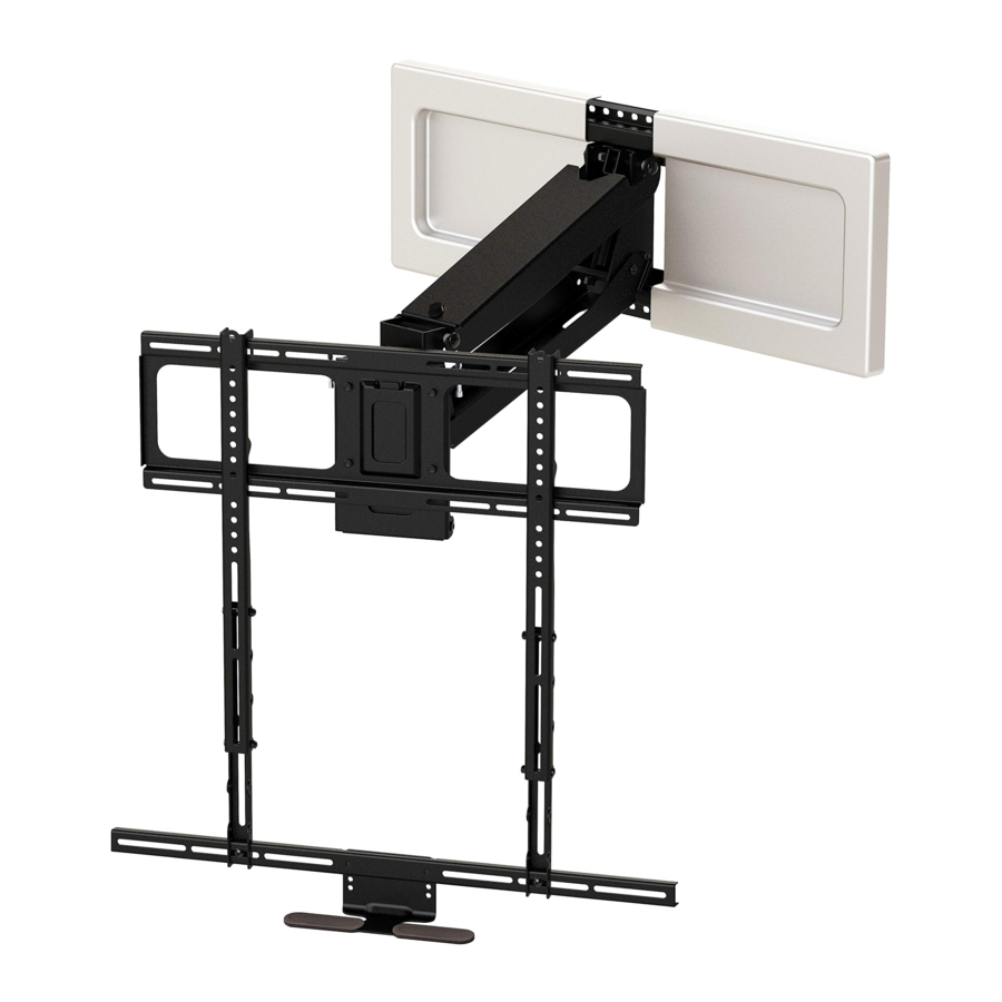
MantelMount MM540 Manual
- Installation instructions manual (25 pages) ,
- Manual (5 pages) ,
- Installation tips (4 pages)
Advertisement
BEFORE INSTALLATION
- Verify TV and mount space meet these criteria:
![]()

- Verify MantelMount will fit the wall space.
![]()
- Use the reference diagram (right) and chart (below) to write down the following measurements (in inches):
Wall Space Height : (Distance from mantel to ceiling/crown moulding.)
TV Height: (Include sound bar height if placing below TV.)
Mantel Depth: (Distance mantel extends away from the wall.)
Required Vertical Space: (Calculation from chart below.)
- Use the reference diagram (right) and chart (below) to write down the following measurements (in inches):

- If the Required Vertical Space is less than or equal to the Wall Space Height, then MantelMount will fit the wall space.
| If Mantel Depth is: | Required Vertical Space is: |
| Less than 9" | TV height + 4" |
| 9" – 11" | TV height + 5" |
| 11" – 14" | TV height + 6" |
| 14" – 18" | TV height + 8" |
- Verify you have the required tools.
![]()
![]()
- Verify all parts are included.
![]()


INSTALLATION STEPS

Keep children away from the work area during installation.
This product contains small parts, please keep out of reach from children.
Do not remove the gas springs or any bolts that hold the Lifting Arm together.
Do not let small children pull on or hang from MantelMount.
Only persons tall enough to control the product all the way to the top/raised position should operate MantelMount.
Do not allow small children to push MantelMount upward to the top position. This will cause the mount to slam against the wall due to the upward force of the springs.

This product is intended to be installed by professional contractors or persons familiar with the tools and methods required for this installation.
If you are uncertain about your ability to perform this installation, please contact a professional.
Do not use this product for purposes not specifically described in these instructions.
MantelMount is not responsible for damage or injury caused by incorrect installation or improper use.
Symbols Used in this Manual

 Two people required for parts of this installation.
Installation Tips & Videos: http://mantelmount.com/install-tips
Questions during installation? Contact Customer Support Monday – Friday, 7am– 4pm PST 1.800.897. 9755 x1 or support@mantelmount.com
STEP 1 Attach Braces to TV

- Test-fit Brace components on back of TV.
Place TV screen-side down on a flat, blanketed surface. Lay out components to check assembly configuration. If installing a sound bar, refer to STEP 8.

- Determine if TV has a flat or irregular back.
An irregular back will require Spacers {12} and longer Screws to fill spaces between the Vertical Brace {31} and the TV. The Braces must be parallel to television screen.

- Select Screws and Spacers.
If Spacers {12} are required, choose one of these Screw combinations shown with maximum Spacer usage.

- Hand-thread screw combination into the TV.
Ensure there is adequate thread engagement without hitting the bottom of threaded insert.

![]()
Do not use screws that are too long for the TV's threaded inserts because it may damage internal components! - Attach the Vertical Braces to the back of TV.
Install the Vertical Braces {31} so that the bottoms of the braces are between 3" to 10" from the bottom of TV, centering the braces vertically as much as possible.

![]() If the lower VESA holes are less than 3" from the bottom of TV, go to STEP 6; otherwise skip to STEP 7.
If the lower VESA holes are less than 3" from the bottom of TV, go to STEP 6; otherwise skip to STEP 7. - OPTIONAL If the lower VESA holes are less than 3" from the bottom of the TV:
Connect the Vertical Braces {31} through the UPPER VESA holes only, so that the bottom of the braces are between 3" to 10" from the * bottom of the TV. If the only option is to attach the Vertical Braces to the UPPER VESA holes through a slot:- Hand-thread the screw through the slot;
- slide the Vertical Brace upward until the screw meets the bottom of the slot; and
- tighten the screw.
![]()
![]() You must attach the Brace Extenders {30} to the Vertical Braces as described in STEP 7. However, you must also attach the LOWER VESA hole through the Brace Extender as shown.
You must attach the Brace Extenders {30} to the Vertical Braces as described in STEP 7. However, you must also attach the LOWER VESA hole through the Brace Extender as shown.
![]()
* If installing this mount with a MantelMount RB100 Recess Box, the bottom of the Vertical Brace must be 7"–10" from bottom of TV.
- Attach the Horizontal Brace to Brace Extenders.
Slide one Brace Extender {30} onto the left end of the Horizontal Brace {55}, then slide the other Brace Extender onto the opposite right end.

Align the Brace Extenders with the Vertical Braces (that are already mounted to the back of the TV) while positioning the Horizontal Brace so that it extends an equal amount on either side of the Brace Extenders.
Attach Horizontal Brace to Brace Extenders w/Screws {15}. - OPTIONAL If installing a sound bar, attach the Sound Bar Wings.
Use Screws {15} and Nuts {23} to attach the Sound Bar Wings {59} to the Horizontal Brace {55}. Position the Wings to fit the mounting holes of the sound bar. Install sound bar. See below for Sound Bar Wing installation information.

Arrange Sound Bar Wings and sound bar to work with the Heat-Sensing Center Handle.
The Sound Bar Wings may be positioned and rotated so that the Center Handle {53} will reach below the sound bar.
For example, if a sound bar is tall, the Brace Extenders {30} and Horizontal Brace can be attached lower down on the Vertical Braces toward the bottom of the sound bar while the Wings point upwards in order to align with the sound bar's installation holes.

- Attach Brace Extenders to the Vertical Braces.
Slide the Brace Extenders {30} (with the Horizontal Brace {55} now attached to them) onto the Vertical Braces {31}. Position it so that the Horizontal Brace will be hidden by the TV. Use Screws {18} and Nuts {23} to attach.

- Attach Heat-Sensing Center Handle to Horizontal Brace.
Attach the Center Handle {53} with Screws {15} to the Horizontal Brace {55}, ensuring that the Handle is within one inch from the bottom of the TV or sound bar.


 Protect the TV with Heat-Sensing Center Handle.
The patented Heat-Sensing Handle turns red if the temperature above the fireplace exceeds a safe 110°F – a visual cue that either the TV needs to be raised to the UP position or the fireplace needs to be turned off.
 To effectively lower the TV using the Handle, follow the MantelMount Three-Step Pull Down Technique:
- Stand in front of the mount, arms extended with palms up and elbows straight.
- Firmly grasp the lifting handles and lean back slightly with one foot forward and one foot back.
- Step backward with forward foot to pull the mount away from the wall while placing downward pressure on the handles (keep elbows extended).
STEP 2 Determine Wall Placement

- Measure the distance from the bottom of the Vertical Braces {31} (not the Extenders) to the bottom of the TV/ sound bar. *
![]()
* If installing this mount with a MantelMount RB100 Recess Box, the bottom of the Vertical Brace must be 7" from bottom of TV. - Determine the minimum vertical position of the Wall Plate.
Use the Look-up Table below to find the minimum distance between the mantel and the bottom of the lower Wall Plate {32}. This will be the intersection of the distance from STEP 1 and the mantel depth. Write the minimum distance in the box below.

![]() Most customers want their TV mounted as close to the mantel as possible. If this describes you, go directly to STEP 4.
Most customers want their TV mounted as close to the mantel as possible. If this describes you, go directly to STEP 4.
However, if you want the TV higher on the wall (such as centered between the mantel and ceiling) e.g. for extra space on the mantel for pictures or a center speaker, continue to STEP 3. - OPTIONAL Determine a higher vertical position of the Wall Plate.
Some customers want the TV centered between the mantel and the ceiling or crown moulding. Others want enough space below the TV for pictures or a center speaker. The TV's position on the wall is directly related to the placement of the lower Wall Plate. To determine exactly where to place the lower Wall Plate, choose an option below that best describes your scenario and fill in the boxes.
Option 1: I want the TV centered between the mantel and ceiling/crown moulding.


- Record measurements already taken:
Wall Space Height![]()
TV Height![]()
Distance from STEP 1![]()
- Subtract the TV Height (B) from the Wall Space Height (A), then divide by 2.
![]()
- Add (C) and (D) to determine how many inches above the mantel to place the lower Wall Plate holes.
![]()
![]()
![]()
Option 2: I want the TV a specific distance above the mantel.


- Record distance from STEP 1
![]()
- Write the specific number of inches you want between the mantel and the TV (or TV with sound bar):
![]()
- Add (C) and (D) to determine how many inches above the mantel to place the lower Wall Plate holes.
![]()
![]()
- Find the center of your mantel and the centers of two studs.
Measure and mark the center line of the mantel onto the wall with tape. Next, use a stud finder to locate two studs, one on each side of the centerline. (If you prefer to use one center stud alone, see "Mount Space" in the Troubleshooting Tips) Then, at the height from either STEP 2 or 3, locate the center of the stud(s) by poking a sharp awl or finish nail through the drywall to find each stud edge. Mark these center spots on the wall. Lag Bolts must be installed into the CENTER of the studs in STEP 4 of the next chapter.

- Determine the positioning of the Wall Plates.
Position the LOWER SLOTS of the Template at the appropriate distance from the mantel according to placement preferences from either STEP 2 or 3. Use a level to orient the Template. Mark the center of the four slots along the marks for the centers of the studs. This should create a cross mark for each hole to drill. Correctly orient a loose Wall Plate {32} to the LOWER hole markings (with slots down) and then the UPPER holes (with slots up). Determine if you can perfectly center the Wall Plate over the mantel while reaching two studs, and without interfering with a wall outlet. If there are no issues, skip to STEP 1 of the next chapter. Otherwise, proceed to STEP 6.

-
- Slide the Wall Plates sideways on the wall until they reach two studs.
The Wall Plates {32} don't have to center-align with the Lifting Arm {35} or the mantel. As long as the Wall Plates are bolted into studs, the Lifting Arm can slide within them, allowing it (and therefore the TV) to center-align with the mantel. Slide the Wall Plates sideways until they reach two studs, and then mark the center line of the wall onto the Wall Plates. Remember to correctly orient the Wall Plates as shown in this image and keep track of which Wall Plate is the UPPER and LOWER (don't accidentally reverse them).

- If necessary, move Wall Plates to clear an outlet.
![]() If a Wall Plate installation is impeded by an electrical outlet (or other) and professionally relocating the outlet is impossible, try one of these options:
If a Wall Plate installation is impeded by an electrical outlet (or other) and professionally relocating the outlet is impossible, try one of these options:
- Move Wall Plates left or right to clear the outlet. The Lifting Arm can be attached anywhere within the Wall Plates in order to center the TV above the mantel, making it adaptable for many installation situations.
- Move Wall Plates up or down to clear the outlet. As long as you don't place the LOWER Wall Plate below the Minimum Distance (STEP 2) or above the Maximum Distance (STEP 3), MantelMount will still function properly. Simply move the Wall Plates up or down enough to clear the outlet, leaving them as close as possible to the originally planned vertical positions. Next, move the Vertical Braces {31} on the back of the TV using the same number of inches used to move the Wall Plates (e.g., move the Vertical Braces up 2" if the Wall Plates were moved up by 2"). The bottom of the Vertical Braces must remain between 3 to 10 inches from the bottom of the TV. If outlet is directly behind the Lifting Arm, the only solution is to move the Wall Plates up.

- Slide the Wall Plates sideways on the wall until they reach two studs.


MantelMount MM540 is designed to swivel 30° left and 30° right. Most TVs will swivel all the way to the mantel or wall within this amount of standard swivel.
 However, for situations where more swivel to one side only is desired, such as in a corner or on a side wall, the optional One-Way Swivel Kit will provide 60° of swivel in either the left or right direction (but not both). This situation is recommended only for a mounting situation that does not include a mantel.
Note: The Auto-Straightening feature does not work with the One-Way Swivel Kit. The TV will need to be manually straightened so it's parallel with the wall when raising it to the UP position.

- Install the One-Way Swivel Kit if you want your TV to swivel 60° in only one direction and you are not mounting it above a mantel.
- Remove the Swivel TV Plate {34} from the Lifting Arm {35}. Save all of the hardware for reassembly at the end of this optional step.
![]()
- Remove the Swivel TV Plate {34} from the Lifting Arm {35}. Save all of the hardware for reassembly at the end of this optional step.

- Install both Side Swivel Plates {56} onto the Lift Arm. The plates nestle underneath the existing tabs. The Screws {36} are installed in the center hole of each Side Swivel Plate.
![]()

- Re-attach the Swivel TV Plate onto the desired side of the Side Swivel Plates. Follow the reverse order that each part was removed.
![]()

One-Way Swivel Kit Parts

STEP 3 Attach Mount to Wall

- Attach Lifting Arm to Wall Plates.
If you arrived from STEP 5 from the previous chapter then you can attach the Lifting Arm {35} directly to the centers of the Wall Plates (32}. If you arrived from STEP 6 from the previous chapter (or optional STEP 7) then you must align the center of the Lifting Arm to the marks on the Wall Plates, while orienting the Upper and Lower Wall Plate correctly. Install four bolts {14} through the back channels of the Wall Plates into the threaded holes of the Lifting Arm. Tighten securely.

- Verify positioning of the mount with stud(s).
Align the mount to the LOWER marked spots on the wall and verify that the markings for the two UPPER hole locations are accurate. Fine tune the upper marks if necessary.


If the Lifting Arm is blocking a Wall Plate hole you need to access:
Move the Wall Plates {32} to the left or right of the desired position and temporarily install it. Use four Lag Bolts {17} to secure the Wall Plates to the studs. This will allow you to pull the Lifting Arm {35} down and install the Safety Bolt (see STEP 1 from the next chapter) in order to access the blocked Wall Plate hole. Then, remove Lag Bolts and reinstall the mount in the desired position. For assistance, contact Customer Support.

- Drill four pilot holes.
Use a 7/32" drill bit to create a depth of 2.5" (65mm), including wall covering.
![]() Wall covering (drywall) must not exceed a thickness of 5/8".
Wall covering (drywall) must not exceed a thickness of 5/8".

- Attach the Wall Plates and Lifting Arm (referred to as the "mount" from this step forward) onto the wall.
Install Lag Bolts {17} and Washers {11} through the Wall Plate {32} holes, directly into the center of the studs, using the pilot holes drilled in STEP 3.


Do not over-tighten Lag Bolts, it can cause property damage or injury. Tighten only until the washers are firmly against the Wall Plate.
- Insert Cable Tie Anchors into Lifting Arm.
Insert two Cable Tie Anchors {22} into the front holes on the lower part of the Lifting Arm {35}. Press firmly until flat.
![]()
- Use the included Cable Ties to attach cables.
Ensure Cable Ties {24} are sideways to the lower part of the Lifting Arm {35}, making a gentle loop. The figure below illustrates the recommended way to attach cables.
![]() Cables must be long enough to accommodate the extension and swivel of the mount. Check all ranges of motion before tightening the Cable Ties.
Cables must be long enough to accommodate the extension and swivel of the mount. Check all ranges of motion before tightening the Cable Ties.

- Attach the TV Brace to the Lifting Arm.
Hang the TV Brace {33} onto the Lifting Arm {35} and make sure it's level when tightening the four Leveling Screws {15}.


STEP 4 Attach TV to Mount

Do not damage or scratch the rods of the Gas Springs while performing these steps!

Do not put hands into Lifting Arm without the Safety Bolt and Safety Nut installed. The force of the Lifting Arm can cause bodily injury!

![]() Insert the Safety Bolt and Safety Nut.
Insert the Safety Bolt and Safety Nut.
Use your body weight to firmly pull down the TV Brace {33} until the Lifting Arm {35} is horizontal to the floor. Continue holding onto the TV Brace.
![]() A second person must insert the Safety Bolt {20} through the Safety Hole in the base of the Lifting Arm and install the Safety Nut {27}.
A second person must insert the Safety Bolt {20} through the Safety Hole in the base of the Lifting Arm and install the Safety Nut {27}.
Slowly release the TV Brace until the Lifting Arm gently comes to rest against the Safety Bolt. The Lifting Arm should remain in a horizontal position during installation. You will later remove the Safety Bolt in STEP 4 in the next chapter.

![]() Carefully hang the TV on the TV Brace.
Carefully hang the TV on the TV Brace.
Make sure that all the hooks on the Vertical Braces {31} engage the TV Brace {33}.
![]() If the Lifting Arm {35} appears to be too close to the mantle, remove the TV. Refer to STEP 3 in the next chapter and make an adjustment to the Bottom Stop positions. Repeat this process until the Lifting Arm is a safe distance from the mantle when the TV is installed.
If the Lifting Arm {35} appears to be too close to the mantle, remove the TV. Refer to STEP 3 in the next chapter and make an adjustment to the Bottom Stop positions. Repeat this process until the Lifting Arm is a safe distance from the mantle when the TV is installed.
![]() Do not allow the TV to drop far enough to cause the Lifting Arm to hit the mantel.
Do not allow the TV to drop far enough to cause the Lifting Arm to hit the mantel.

- Center and level the TV on the TV Brace.
Make sure the center of the brace is aligned with the center of the TV before leveling. Move on to STEP 4 once the TV is level. If the TV sags to one side, carefully slide it sideways in the opposite direction up to a MAXIMUM of 2 inches, until it levels.
![]() If the TV is now level but appears noticeably off-center above the mantel, remove the TV and relocate the Wall Plates {32} an equal distance in the opposite direction to compensate. Repeat STEPS 3 and 4 from the previous chapter.
If the TV is now level but appears noticeably off-center above the mantel, remove the TV and relocate the Wall Plates {32} an equal distance in the opposite direction to compensate. Repeat STEPS 3 and 4 from the previous chapter.
![]() If you experience additional issues leveling the TV, refer to "TV Leveling" in the Troubleshooting Tips.
If you experience additional issues leveling the TV, refer to "TV Leveling" in the Troubleshooting Tips.

- Attach the TV Brace to the Vertical Braces.
Install four Screws {15} through the TV Brace {33} and into the Vertical Braces {31}.

- Attach the electrical and signal cables to the TV.
Give each segment of the cables extra length so that they are not stressed or kinked when the mount moves.
![]() Ensure that cables do not get pinched within the Lifting Arm when the TV is raised.
Ensure that cables do not get pinched within the Lifting Arm when the TV is raised.


STEP 5 Make Final Adjustments

- Adjust the Lifting Force for the TV.
First, review all the images in this step.
With Safety Bolt {20} in place, use a 10–14mm socket wrench with an extension to adjust the Tension Bolt {41} (the long bolt inside the Lifting Arm {35}). For heavy TVs, turn the Tension Bolt clockwise in order to pull the Gas Springs {38} DOWN and increase the lifting force. Turn counterclockwise for lighter TVs.
![]() The Gas Springs move slowly as you turn the Tension Bolt. Their movement is subtle. Please be patient as it may take multiple revolutions to reach the desired tension.
The Gas Springs move slowly as you turn the Tension Bolt. Their movement is subtle. Please be patient as it may take multiple revolutions to reach the desired tension.
Adjust the Tension Bolt until the TV gently stays in the lowered position. Move the TV up and down within the range below the Safety Bolt. The TV should almost stay up against the Safety Bolt and slowly lower to the Bottom Stops when released.
![]()
![]()


Do not adjust the Tension Bolt all the way to the bottom – your mount won't function properly in that position.
- Adjust the Side Swivel Stop positions, if necessary.
To keep the TV from bumping the mantel or wall, loosen the Locknuts {23} and adjust the Swivel Stop Screws to the desired stopping left and right positions. Tighten both Locknuts after the adjustments are made.
![]() If no swivel is desired, it may be necessary to remove the Locknuts and reattach them on the other side of the Swivel Bracket so that the Screws can be threaded out to their maximum length.
If no swivel is desired, it may be necessary to remove the Locknuts and reattach them on the other side of the Swivel Bracket so that the Screws can be threaded out to their maximum length.
![]()
- Adjust the Bottom Stop positions and level the TV, if necessary.
To keep the TV from hitting the top of the mantel or dropping too low, adjust the Bottom Stop screws on each side of the Lifting Arm {35}. Loosen the Locknuts {23} and adjust the Bottom Stop screws to the desired stopping position, and tighten the Locknuts. Next, place a level on top of the TV. If the TV is not level in the DOWN position, adjust one of the bottom stop screws until the TV is level.
![]()
- Remove the Safety Bolt and Safety Nut.
Store these parts for future use.
The Safety Bolt {20} and Safety Nut {27} are needed to remove the TV at any time in the future.
![]()


Never release the handle before the TV mount is fully upright. (Don't let it slam up!) MantelMount is strongest in the top position, and allowing it to slam closed can damage televisions. Always control the lifting process.

- Verify the proper Lifting Performance (Force).
MantelMount is designed to keep the TV securely in the UP position while also allowing it to gently rest in the DOWN position. Refer to diagram below. If you need to make adjustments, reinsert the Safety Bolt and then repeat STEP 1. For more information on refining Lifting Performance, refer to "Mount Performance" in the Troubleshooting Tips.
![]()
- Make Post-Leveling adjustments, if necessary.
Place a level on top of the TV while it's in the UP position. If it's level, the installation is complete! If not, slightly loosen all four Leveling Screws {15} and rotate the TV until it's level and then tighten all the Screws.
![]()
- Adjust the Vertical Tilt Position.
Locate the two sliding knobs on each side of the Tilt Mechanism on the Lifting Arm {35}. Slightly loosen the knobs and position the TV to the desired tilt, then tighten the knobs. The tilt will remain at the same angle while the mount is raised or lowered, unless it is manually changed.
![]()
- Install the Wall Plate Covers.
For wiring inside the Wall Plates {32}, use a Hole Saw drill bit to cut a hole through a Wall Cover {57}. Be careful not to damage the edge around the hole.
![]() For best results, support the Wall Cover with scrap wood behind the drilling area. Paint the Wall Covers if desired. Once dry, snap them onto the Wall Plates.
For best results, support the Wall Cover with scrap wood behind the drilling area. Paint the Wall Covers if desired. Once dry, snap them onto the Wall Plates.
![]()


Thank you for purchasing a MantelMount.
For installation assistance, refer to the Troubleshooting Tips or contact Customer Support.
1.800.897.9755 ext.1
support@mantelmount.com
Monday – Friday
7:00am – 4:00pm PST
TROUBLESHOOTING TIPS
Customer satisfaction is our top priority!
Following are solutions for the most common installation challenges. For further assistance, visit www.mantelmount.com/troubleshooting or contact ustomer Support at 1-800-897-9755 ext.1 or support@mantelmount.com, Monday through Friday, 7am to 4pm PST.
NOTE: In rare cases, one troubleshooting adjustment may create the need for another. Be prepared for some trial and error.
| MOUNT SPACE | |
| ISSUE | SOLUTION |
| The wall covering is made of brick or stone. | It's possible to install MantelMount by using concrete anchors (included) with the Lag Bolts {17}, PROVIDED the brick/stone/wall is structurally sound, several inches thick, and can handle four times the weight of the TV and mount. Working with a concrete/masonry professional for this type of installation is recommended. |
| The drywall/stucco wall covering is thicker than 5/8". | Please contact Customer Support for guidance before attempting installation. |
| A single wood stud is centered on my wall. | It's OK to mount the Wall Plates to a single stud by driving two Lag Bolts through the center of the Wall Plates and into the center stud, as long as the Lifting Arm ends up positioned directly in front of the stud. Alternatively, for a smaller footprint, replace the Wall Plates with the SSB40 Single Stud Adapter, available at MantelMount.com. |
| MOUNT PERFORMANCE | |
| ISSUE | SOLUTION (May require some trial and error to reach optimal performance.) |
| The Lifting Arm won't pull down in order to insert the Safety Bolt. | It will take some force to pull down the Lifting Arm when it's in the raised position and there is no TV attached. As long as the mount is securely attached to a stud(s) in the wall, it won't break. First, make sure the TV Brace is attached to the Lifting Arm (see Step 7 in Attach Mount to Wall chapter). Next, pull the Lifting Arm down: Stand in front of the mount, reach up and grasp the top or bottom of the TV Brace with both hands, palms facing down. Move one foot back for leverage and straighten elbows. Then lean back, bend both knees and elbows, and pull the mount out and down (see Step 1 in Attach TV to Mount chapter). |
| TV is difficult to pull down. | Use the MantelMount Three-Step Pull-Down Technique:
|
| TV is difficult to lift up. | If the mount is relatively easy to pull down, slightly tighten it when it's in the UP position. Review Step 1 in the Make Final Adjustments chapter to make minor clockwise adjustments to the Lifting Force, then try lifting up the TV again. The goal is to adjust the Lifting Force just enough to comfortably lift the TV without too much effort. However, if it becomes too easy to lift up, it may become difficult to pull down. If you are unable to find a balance between ease of pulling down and lifting up, follow the instructions above and focus primarily on making it easier to pull down. Then make adjustments to the Bottom Stop positions (see Step 3 in the Make Final Adjustments chapter). Lower the Bottom Stops to limit downward travel. The less downward travel, the easier it will be to lift. |
| The mount won't remain stationary anywhere along the route of travel. | Make adjustments to the Lifting Force (see Step 1 in the Make Final Adjustments chapter). The combination of the TV's size and weight, installation height and mantel depth may affect whether the TV can rest at various positions along the route of travel. What's most important is that the TV can comfortably pull down/lift up and stop at the optimal viewing height. |
| TV is not lowering the full vertical travel listed in the specifications. | If you can comfortably pull down and lift the TV but would like for it to drop below the lowest Bottom Stop Position, remove the Bottom Stop Screws on each side (see Step 3 in the Make Final Adjustments chapter); the TV will travel even lower. However, proceed with caution. If the TV is above a mantel, removing the Bottom Stop Screws may cause the Lifting Arm to hit the top of the mantel. |
| TV is tilting forward when in the UP position. | This is generally an indication that the Lifting Force is not set tight enough in the UP position (see Step 1 in the Make Final Adjustments chapter). Slightly turn the Tension Bolt clockwise and try again. The goal is to adjust the Lifting Force just enough for the TV to no longer tilt in the UP position. Be careful not to set the Lifting Force too tightly in UP position or the TV may not fully lower to the optimal viewing position. | ||
| TV LEVELING | |||
| ISSUE | POSSIBLE CAUSE | HOW TO CHECK | SOLUTION |
| TV is not level in the UP and/or DOWN positions. | The mantel, ceiling or floor may not be level. | Compare TV level with that of the mantel and floor. |
|
| Vertical Braces aren't evenly attached. | Look at the back of the TV and ensure that the top of the Vertical Braces are parallel to one another. |
| |
| Wall Plates aren't level. | Use a level on top of Wall Plates to verify that it's not level. |
| |
| TV is level in the UP position, but unleveled in the DOWN position. | The Bottom Stops aren't evenly set. | Use a level to verify the TV is level in the UP position but not in the DOWN position. | Follow the instructions in Step 3 in the Make Final Adjustments chapter. Be prepared for some trial and error. If adjusting the Bottom Stops doesn't solve the problem, try the solution below for when a TV is heavier on one side. |
| TV is heavier on one side. | Use a level to verify the TV is level in the UP position but not in the DOWN position. | Attach a counterweight to the back of the TV. Contact Customer Support for assistance. | |
| TV is level in the DOWN position, but unleveled in the UP position. | Post-Leveling Adjustments haven't been made. | Use a level on top of the TV to verify it's leveled in the DOWN position but not in the UP position. | Refer to Step 6 in the Make Final Adjustments chapter and make adjustments. |
SPECIFICATIONS

- TV Weight Capacity: 20–90 pounds
- TV Screen Size: 44" – 80" diagonal
- Maximum Lowering Distance: 27"
- Thickness from Wall: 5.7"
- Mount Weight: 37.4 lbs.
- Steel Thickness: 2.5mm
- Swivel: 30° Left and 30° Right
- Tilt: 9°
- VESA Pattern 600mm x 600mm
- Dimensions: 34"w x 25.2"h x 5.5"d
For more information on MantelMount patented technology visit: www.mantelmount.com/pages/patents
Limited Liftetime Warranty: MantelMount will replace or repair any product or part that proves defective due to improper workmanship or material during the warranty period. Go to www.mantelmount.com/pages/limited-lifetime-warranty for details.
If you need help, call 1.800.897.9755 ext.1
For missing/damaged parts or questions during installation, please contact our Customer Support team at 1.800.897.9755 ext.1 or support@mantelmount.com. Customer satisfaction is our highest priority!
Contains important safety information – please save!
MantelMount.com
MAILING ADDRESS: 2647 Gateway Road Ste. 105-435 Carlsbad, CA 92009
mantelmount.com
Documents / Resources
References
![www.mantelmount.com]() MantelMount Patents
MantelMount Patents![mantelmount.com]() MantelMount Install Tips
MantelMount Install Tips![www.mantelmount.com]() The Perfect Pull Down TV Mount Above Your Fireplace | MantelMount
The Perfect Pull Down TV Mount Above Your Fireplace | MantelMount![mantelmount.com]() The Perfect Pull Down TV Mount Above Your Fireplace | MantelMount
The Perfect Pull Down TV Mount Above Your Fireplace | MantelMount![www.mantelmount.com]() Lifetime Limited Warranty | MantelMount
Lifetime Limited Warranty | MantelMount
Download manual
Here you can download full pdf version of manual, it may contain additional safety instructions, warranty information, FCC rules, etc.
Advertisement


Need help?
Do you have a question about the MM540 and is the answer not in the manual?
Questions and answers