Hach SC4200c User Manual
Hide thumbs
Also See for SC4200c:
- User manual ,
- User instructions (328 pages) ,
- Basic user manual (88 pages)
Table of Contents
Advertisement
Quick Links
Advertisement
Table of Contents

Related Manuals for Hach SC4200c


Summary of Contents for Hach SC4200c
- Page 1 DOC343.52.90586 SC4200c 06/2019, Edition 7 User Manual...
-
Page 3: Table Of Contents
Table of Contents Specifications ......................3 General information ....................3 Safety information ......................4 Use of hazard information ..................4 Precautionary labels ..................... 4 Chemical and biological safety ................5 Certification ......................5 Product overview ......................7 Product components ....................9 Installation ........................ - Page 4 Table of Contents Cleaning the controller ....................29 Troubleshooting ....................... 29 LED status ......................... 29 Connection problems ....................30 Replacement parts and accessories ............... 30...
-
Page 5: Specifications
Specifications Specifications are subject to change without notice. Specification Details Dimensions (W x H x D) ½ DIN—144 x 144 x 192 mm (5.7 x 5.7 x 7.6 in.) Weight 1.7 kg (3.7 lb) (Controller weight without optional modules) Enclosure NEMA 4X/IP66 metal enclosure with a corrosion-resistant finish Operating temperature –20 to 60 °C (–4 to 140 °F);... -
Page 6: Safety Information
Safety information N O T I C E The manufacturer is not responsible for any damages due to misapplication or misuse of this product including, without limitation, direct, incidental and consequential damages, and disclaims such damages to the full extent permitted under applicable law. -
Page 7: Chemical And Biological Safety
Chemical and biological safety D A N G E R Chemical or biological hazards. If this instrument is used to monitor a treatment process and/or chemical feed system for which there are regulatory limits and monitoring requirements related to public health, public safety, food or beverage manufacture or processing, it is the responsibility of the user of this instrument to know and abide by any applicable regulation and to have sufficient and appropriate mechanisms in place for compliance with applicable regulations in the event of malfunction of the instrument. - Page 8 Regulatory RF Device Approvals: EU Contains RF Cellular Module: Telit LE910-EU V2 Dual-Band GSM/GPRS/EDGE EGSM900/DCS1800 Dual-Band WCDMA/HSPA FDD I / FDD VIII Penta-Band LTE FDD 1 / FDD 3 / FDD 7 / FDD 8 / FDD 20 wireless module Table 2 Power for Cellular Modem: EU Standard Operating frequency bands...
-
Page 9: Product Overview
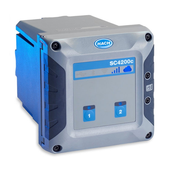
The SC4200c is a 2-channel controller for digital sensors. Refer to Figure The controller is configured and operated with a Mobile sensor management (MSM) software. The MSM software is accessible through a web application on a customer-supplied device with an internet browser that is connected to the internet. - Page 10 Figure 1 Product overview 1 Label for module installation 6 USB connection 2 Power indicator light 7 USB cover 3 SIM card 8 Electrical connections and fittings 4 Expansion module 9 Cover for module installation 5 Additional expansion module slots 10 High-voltage barrier Dependent on controller configuration.
-
Page 11: Product Components
Figure 2. If any items are missing or damaged, contact the manufacturer or a sales representative immediately. Figure 2 Product components 1 SC4200c controller 8 Flat washer, ¼-inch ID (4x) 2 Mounting hardware 9 Lock washer, ¼-inch ID (4x) 3 Sealing gasket for panel mount, Neoprene 10 Keps hexnut, M5 x 0.8 (4x) -
Page 12: Installation Guidelines
"donotreply@hach.com" sends the system notifications that are necessary for the installation. Add the two email addresses to the safe senders list to make sure to receive mails from these senders. Hach does not send a request to confirm that the sender is not a robot. -
Page 13: Attach The Instrument To A Pole
Figure 3 Wall mounting Attach the instrument to a pole Attach the controller upright to a pole or pipe (horizontal or vertical). Make sure that the pipe diameter is 19 to 65 mm (0.75 to 2.5 in.) Refer to the illustrated steps in Figure 4 Product components on page 9 for the necessary mounting hardware. -
Page 14: Install The Instrument In A Panel
Figure 4 Pole mounting Install the instrument in a panel A rectangular hole is necessary for panel installation. Use the supplied sealing gasket for panel mount as a template to cut the hole in the panel. Make sure to use the template in the up position to install the controller vertical. -
Page 15: Electrical Installation
Figure 5 Panel mounting dimensions Electrical installation Electrical connectors and fittings Figure 6 shows the electrical connectors and fittings on the instrument. To keep the environmental rating of the enclosure, make sure that there is a plug in the strain relief fittings that are not used and a connector cap on the unused connectors. -
Page 16: Electrostatic Discharge (Esd) Considerations
Electrostatic discharge (ESD) considerations N O T I C E Potential Instrument Damage. Delicate internal electronic components can be damaged by static electricity, resulting in degraded performance or eventual failure. Refer to the steps in this procedure to prevent ESD damage to the instrument: •... -
Page 17: Wiring For Power
Figure 8 High-voltage barrier Wiring for power D A N G E R Electrocution hazard. Protective Earth Ground (PE) connection is required. D A N G E R Electrical shock and fire hazards. Make sure to identify the local disconnect clearly for the conduit installation. -
Page 18: Connect Conduit Or A Power Cord
Supply power to the instrument with conduit or a power cable. Make sure that a circuit breaker with sufficient current capacity is installed in the power line. The circuit breaker size is based on the wire gauge used for installation. For installation with conduit: •... -
Page 19: Connect The High-Voltage Relays
Figure 9 Connect conduit or a power cord 1 AC power terminal 3 Protective earth ground 2 Cables limit: do not put cables above the line. 4 Conduit hub (or strain relief fitting for power cord) Table 3 Wiring information—AC power Terminal Description Color—North America... - Page 20 W A R N I N G Explosion hazard. This manual is only for installation of the unit in a non-hazardous location. For installation of the unit in hazardous locations, use only the instructions and approved control drawing provided in the hazardous location installation manual. C A U T I O N Fire hazard.
-
Page 21: Install An Expansion Module
Figure 10 Connect the relays Table 4 Wiring information—relays Terminal Description Terminal Description Relay 1, NC Relay 2, NC Relay 1, common Relay 2, common Relay 1, NO Relay 2, NO NC = normally closed; NO = normally open Install an expansion module W A R N I N G Explosion hazard. -
Page 22: Close The Cover
™ configuration. Refer to LAN connection on page 24. A Claros connection is necessary to configure the Modbus TCP datagram. A controller with mobile internet connection can connect to Modbus TCP/IP and share the internet connection through LAN. Refer to Figure Note: Make sure that the Modbus TCP master and one of the controllers are on the same IP sub-network. -
Page 23: User Interface
Figure 12 Digital sensor quick connect User interface The keypad has controller icons, sensor status LEDs and two channel buttons. Refer to Figure Figure 13 Keypad and front panel overview 1 Controller icons 4 Channel 2 button—Puts all channel outputs on hold. 2 Sensor status LED for Channel 1 5 Sensor status LED for Channel 2 3 Channel 1 button—Puts all channel outputs on hold. -
Page 24: Startup
Table 5 Icon descriptions (continued) Icon Description Status USB connection Off: no USB flash drive connected Blue on: USB flash drive connected Flashes blue: data transmission WiFi connection Off: no WiFi connection Blue on: Controller connected to a WiFi access point. Table 6 Sensor Status LED descriptions LED status Description... -
Page 25: Configure The Ip Address Of The Pc
5. Select OK to confirm the settings. Note: Change the settings to the initial values when the configuration is completed. 6. Open the web browser on the PC. Enter the IP address that follows to connect to the SC4200c Controller. -
Page 26: Operate The Web Server Application
3. Go to the Ethernet configuration page and configure the LAN connection. Note: An internet connection is not necessary to complete this configuration. 4. Open the web browser on the PC. Enter the IP address that follows to connect to the SC4200c controller: "http://192.168.165.30"... -
Page 27: Share The Lan
Figure 15 Network sharing Mobile network connection If the controller connects to the internet with the factory installed SIM card and the default Hach data plan, no more steps are necessary. To change the SIM card and connect the controller to the internet with a cellular network through a customer supplied data plan, do the steps that follow: 1. -
Page 28: Wifi Network Connection
4. Configure the modem. Note: An internet connection is not necessary to complete this configuration. 5. Open the web browser on the PC. Enter the IP address that follows to connect to the SC4200c controller: "http://192.168.165.30" 6. Select the Modem menu. -
Page 29: Operation
5. Select Apply to save the settings. Operation Use the MSM software to interact with the connected measurement devices. Contact Hach Technical Support to get a Claros Mobile Sensor Management account for the first time. Note: Refer to the manufacturer's website to find more information about the MSM software. -
Page 30: Connect A Usb Flash Drive (Optional)
4. When the update is complete, remove the USB flash drive. Note: The USB icon in the front panel flashes to show data transmission. Do not remove the USB flash drive until the light flashing stops. 5. Close the USB cover. Connect a USB flash drive (optional) W A R N I N G Explosion hazard. -
Page 31: Cleaning The Controller
Cleaning the controller D A N G E R Always remove power from the controller before performing maintenance activities. Note: Never use flammable or corrosive solvents to clean any part of the controller. Use of these solvents may degrade the environmental protection of the unit and may void the warranty. 1. -
Page 32: Connection Problems
Problem Possible cause Solution The sensor status LED Sensor connection issue Examine the sensor and the sensor cable for stays off, but the second damage. If damage is found, contact technical sensor operates. support. If no damage is found, disconnect the sensor, wait for 15 seconds, then connect the sensor again. - Page 33 Description Item number Power Cord Kit, SC4200c, strain relief, 120 VAC, U.S. plug LXZ524.99.00034 Power Cord Kit, SC4200c, strain relief, 240 VAC, EU plug LXZ524.99.00035 Power Cord Kit, SC4200c, strain relief, UK LXZ524.99.00038 SC4200c UV protection screen LXZ524.99.00004 SC4200c UV protection screen with sunroof LXZ524.99.00005...
- Page 34 32 English...
- Page 36 Tel. +49 (0) 2 11 52 88-320 SWITZERLAND Fax (970) 669-2932 Fax +49 (0) 2 11 52 88-210 Tel. +41 22 594 6400 orders@hach.com info-de@hach.com Fax +41 22 594 6499 www.hach.com www.de.hach.com © Hach Company/Hach Lange GmbH, 2017–2019. All rights reserved.
Need help?
Do you have a question about the SC4200c and is the answer not in the manual?
Questions and answers