Advertisement
Quick Links
Advertisement

Related Manuals for McLelland CPA-501


Summary of Contents for McLelland CPA-501
- Page 1 CPA‐5 501/CPA A‐501T SINGL E CHANN NEL POW WER AMP PLIFIER ...
- Page 2 ...
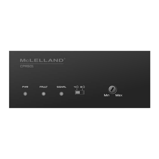
- Page 3 RONT PANE EL PWR: Green n LED, indica ates operat ting power s supplied fro om AC line p power FAULT: Red LED, indicat tes an over‐ ‐temperatu ure or over‐c current faul lt SIGNAL: Bi‐c color Green n/Red LED, g green indica ates input s signal prese nce d red indicat tes without input signa al Output Swit tch: 4Ω/8Ω switch on t the front pa anel of CPA‐ ‐501 ...
- Page 4 OPERATING DIAGRAM ...
- Page 5 Assemble Diagram Before the amplifier can be installed a rack, please prepare the optional rack ears and Fix plate, and then follow below steps to install. A: Assemble Single Amplifier A mplifier Dimens ion Unit: mm Ra ck Ear ( L) Unit: mm Optional part Ass emble Diagram Finis hed Diagram ...
- Page 6 SPECIFICATIONS CPA‐501 CPA‐501T Output Channel 1 1 Max. Output / CH 50 W @ 4Ω/8Ω 50 W @ 70V/100V Frequency Response 20Hz~22KHz +0/‐3dB @ 4Ω 20Hz~15KHz +0/‐3dB @ 70V/100V THD @ Max power < 1% @ 4Ω < 1% @ 4Ω THD @ 1/8 full power < 0.2% @ 4Ω < 0.2% @ 4Ω Signal‐to‐Noise Ratio > 98dB ...
Need help?
Do you have a question about the CPA-501 and is the answer not in the manual?
Questions and answers