
Related Manuals for McLelland CA1250


Summary of Contents for McLelland CA1250
- Page 1 CA1250 Right Left Right Left Right Left Right Left Right Left Right Left 12 CHANNEL 6 ZONE INTEGRATED AMPLIFIER CA1250...
-
Page 2: Important Safety Instructions
Important Safety Instructions RISK OF ELECTRIC SHOCK DO NOT OPEN RISQUE DE CHOC ÉLECTRIQUE N'OUVREZ PAS CAUTION: To reduce the risk of electric shock, do not remove cover (or CAUTION: TO PREVENT ELECTRIC back). SHOCK, MATCH WIDE BLADE PLUG TO No user-serviceable parts inside. -
Page 3: Table Of Contents
Table of Contents Important Safety Instructions ......................2 Table of Contents ..........................3 Introduction ............................4 Features............................... 5 What’s Included ..........................5 Front Panel Features .......................... 6 Rear Panel Features ........................... 7 IR Remote Control ..........................9 Installation ............................10 Wiring Infrastructure ........................ -
Page 4: Introduction
70/100V zones (30W/channel); or three high powered bridged zones(100W @ 8 Ohms). By the way, the CA1250 can be configured for any combination of stereo 4 Ohms/ 8 Ohms, 8 Ohms bridged and 70/100V zones all at the same time! And there’s more. -
Page 5: Features
1 - IR Remote Control 1 - AC Power Cord 1 - User Manual CAUTION!!! NEVER CHANGE ANY OF THE FOLLOWING SETTINGS WHEN THE CA1250 IS TURNED ON OR CONNECTED TO AC POWER: 70V/100V HIGH VOLTAGE SPEAKER OUTPUT ZONE STEREO/BRIDGED SWITCH... -
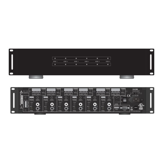
Page 6: Front Panel Features
Front Panel Features 1. RACK EARS - Two, optional rack ears. The CA1250 is 2U rack height. If rack mounting, leave desired. 2. PEAK OUTPUT LEDS - volume setting. This is an indication that the volume setting is approaching maximum...not an a bit to protect the amp and speakers. -
Page 7: Rear Panel Features
7. MASTER CONTROL OUT - One, 3.5mm mini jack. Connect to any voltage controlled device that is to be turned ON/OFF relative to CA1250 ON/OFF Status. When any zone on the CA1250 is ON the Master Control OUT will output 11.5VDC@1mA-10VDC@5mA. When all zones are OFF the Master Control OUT... - Page 8 8 Ohm/4 Ohm and 70V/100V configurations. Bridged - designed to run safely into such a low impedance (which the CA1250 is not) damage may 17. AUDIO BUS - One, plug-in screw terminal. Mono, unbalanced input. This input will send the Audio IN signal to all zones switched to Bus using the Line/Bus Trigger IN.
-
Page 9: Ir Remote Control
IR Remote Control The CA1250 IR Remote Control controls the individual zones on the CA1250. It can also be used to teach IR commands to a programmable, integrated IR remote, zone control system or other IR routing device. controller or IR router will be necessary for centralized control of the individual zones. -
Page 10: Installation
6. When installing the CA1250 in a rack, please use racks that feature a rear support provision. Adding a single RU (Rack Unit) vent above and below the CA1250 will improve convection in heavy use applications. -
Page 11: Wiring Infrastructure
Use quality stranded If the amp is being used to distribute audio from the CA1250 Zone Line INs or Audio Bus IN, to different rooms with 4/8 Ohm speakers, individual room volume controls (or an IR control system) will be needed. -
Page 12: Connections
Connections Speaker Connections High Power High Power 8 Speaker 8 Speaker speaker connections. Bridged 8 Ohms, 4/8 Ohms Stereo and 70V/100V. Any mix of amplifier modes is allowable in different zones...as long as they are configured correctly. NEVER CHANGE THE Bridge 8 70V/100V HIGH VOLTAGE SPEAKER OUTPUT, Set to: 8... -
Page 13: 70V/100V
70V/100V Connection to 70V if CA1250 AC Voltage Select switch is set to 110~120VAC. Set to 100V if CA1250 AC Voltage Select switch is set to 220~240VAC. This setting will affect all zones set to 70V/100V. 2. Stereo/Bridged Switch - Set to the Stereo position. -
Page 14: Audio Connections
AUDIO BUS OUT This connection will send the unbalanced line level audio source connected to the Audio Bus IN to the Jump CA1250 #1 Audio Bus IN on another CA1250 or other audio Audio Bus OUT to CA1250 #2 CA1250 #2 Audio amplifier. -
Page 15: Control Connections
1. IR/GND - Using a 2-circuit 3.5mm mini plug cable, connect the IR Emitter OUT of an IR control system to the IR IN and GND terminals on the appropriate CA1250 zone. Connect the white stripe (tip) to IR IN, connect the black (sleeve) to GND. -
Page 16: Zone Mute
This connection provides a +12VDC 1mA zone control output that can be used to trigger zone specific, voltage controlled devices. When an CA1250 zone is ON, this connection will output a +12VDC control voltage. When the zone is OFF the control voltage is 0.OVDC 1. -
Page 17: Master Control In
This connection provides a voltage control OUT that can be used for triggering voltage controlled system devices that need to be turned ON when any CA1250 zone is active. When any CA1250 zone is ON, the Master Control OUT will output +11.5VDC@1mA-10VDC@5mA. If all zones are 2 Circuit OFF, the Master Control OUT will output 0.0VDC. -
Page 18: Settings
Settings This section covers all of the settings that need to set correctly in order for the CA1250 to function properly. 70/V100V HIGH VOLTAGE SPEAKER OUTPUT Right Left 70V/100V to either 70 volts or 100 volts. This switch is used in conjunction with both the 70V/100V switch setting. -
Page 19: Remote Bypass
110V-120V/60Hz use a T10.0AL/250V fuse. AV Voltage Select/Fuse CAUTION!!! NEVER CHANGE ANY OF THE FOLLOWING SETTINGS WHEN THE CA1250 IS TURNED ON OR CONNECTED TO AC POWER: 70V/100V HIGH VOLTAGE SPEAKER OUTPUT ZONE STEREO/BRIDGED SWITCH VOLTAGE SELECT SWITCH (110/220VAC) DOING SO CAN CAUSE SEVERE DAMAGE TO THE CA1250 AND/OR CONNECTED SPEAKERS. - Page 20 Line Level Audio to CA1250 Zone Line IR Connecting Block A/V Receiver or Line/Preamp Audio Distribution Amp Other Audio Source Switcher Line Level Audio to Hardwired/Docked/ AVR/Switcher Bluetooth CD/Blu-ray/Streaming Media Player Smartphone/ Tablet Portable Music Player Typical CA1250 System Application 20...
-
Page 21: Operation
Operation How the CA1250 is controlled is dependent upon how it is being used. Three basic modes will be There are of course, variations on these three basic control modes that can utilize some options from appropriately. VOLTAGE CONTROLLED This mode would typically be used when the CA1250 is being used purely as a multi-channel power amp with a multi-zone controller or preamp. -
Page 22: Rs232 Controlled
Operation 1. ON/OFF - Press the Power button on the CA1250 IR Remote to turn the zone ON. Press again to turn the zone OFF. 2. Bus/Line - Press the Bus button to select the source connected to the CA1250 Audio Bus In (if used). -
Page 23: Rs232 Commands
RS232 Commands connection instructions in Control Connections/RS232I/O. Then use this section of alpha-numeric text commands to program the controller for CA1250 RS232 control by zone. For Zone status use the RS232 Queries section to get feedback on various zones’ status. - Page 24 RS232 Commands CA1250 RS232 COMMANDS NAME COMMAND REMARKS Bass Decrement !{z#}BD+ Balance !{z#}BA{b#}+ Balance Step Left !{z#}BL+ Balance Step Right !{z#}BR+ Zone Activity Auto Update !ZA{0/1}+ Enable/Disable Auto Update of the Zone Information when Zone Activity is Detected. (See below for format of the output.) Zone Max.
-
Page 25: Rs232 Queries
RS232 Queries CA1250 RS232 QUERIES EXAMPLE NAME QUERY RESPONSE EXPLANATION RESPONSE Zone Volume ?{z#}VO+ ?{z#}VO{v#}+ ?4VO49+ Zone 4 is currently at volume level 49. Channel ?{c#}CH+ ?{c#}CH{v#}+ ?4VO49+ Channel 4 is currently at Volume volume level 49. Mute ?{z#}MU+ ?{z#}MU{0/1}+... - Page 26 RS232 Queries ZA – Zone Activity Auto Update Enable Command. Format - !ZA{0/1}+ ZS – Zone Status Query. Format - ?(z#}ZS+ The Activity Update will cause the system to send out the complete Zone State whenever something in the zone changes. The State string will be sent out one second after activity in the zone stops. Also, the Metadata will be sent out whenever it changes.
-
Page 27: Rs232 Settings
RS232 Settings CA1250 VOLUME LEVEL SETTINGS CA1250 SETTING ATTENUATION LEVEL -1.25 -2.50 -3.75 -5.00 -6.25 -7.50 -8.75 -10.00 -11.25 -12.50 -13.75 -15.00 -16.25 -17.50 -18.75 -20.00 -21.25 -22.50 -23.75 -25.00 -27.50 -30.00 -32.50 -35.00 -37.50 -40.00 -42.50 -45.00 -47.50 -50.00 -52.50... - Page 28 RS232 Settings CA1250 TREBLE/BASS LEVEL SETTINGS CA1250 LEFT/RIGHT BALANCE SETTINGS CA1250 SETTING LEVEL (+/-dB) CA1250 LEFT RIGHT SETTING SPEAKER SPEAKER +/- dDB +/-dB Mute -37.5 -36.25 -2.5 -1.25 -1.25 -2.5 -37.5 Mute...
- Page 29 Audio Sections Continuous Output Power ..........Total Harmonic Distortion ....................Signal-to-Noise Ratio..................90dB A-Weighted 1kHz Channel Separation ....................... 65dB 1kHz Frequency Response ....................20Hz to 20kHz+/-1dB Input Sensitivity ......................600mV @ 30W Tone Control ......................Bass 100Hz +/-12dB Treble ..........................10k Hz+/-12dB Line Input Impedance ......................47 k-Ohms Voltage Control Sections Master Control IN ....................
-
Page 30: Limited Warranty
Notes...
Need help?
Do you have a question about the CA1250 and is the answer not in the manual?
Questions and answers