Advertisement
Quick Links
Advertisement

Related Manuals for Commell LS-373


Summary of Contents for Commell LS-373
- Page 1 LS-373 3.5” Miniboard User’s Manual Edition 1.31 2024/10/21...
- Page 2 LS-373 User’s Manual Copyright Copyright 2008, all rights reserved. This document is copyrighted and all rights are reserved. The information in this document is subject to change without prior notice to make improvements to the products. This document contains proprietary information and protected by copyright. No part of this document may be reproduced, copied, or translated in any form or any means without prior written permission of the manufacturer.
- Page 3 LS-373 User’s Manual Packing List: Please check the package content before you starting using the board. Hardware: LS-373 3.5“ Miniboard x 1 Cable Kit: SATA Cable x 2 DC Power Cable x 1 (OALSATA-L) (OALDC-2) COM Port Cable x 1...
- Page 4 LS-373 User’s Manual Index Chapter 1 <Introduction> ...............7 1.1 <Product Overview> ..............7 1.2 <Product Specification>............. 8 1.3 <Mechanical Drawing > ............. 9 1.4 <Block Diagram> ..............11 Chapter 2 <Hardware Setup>...............12 2.1 <Connector Location> ............. 12 2.2 <Jumper Location & Reference>..........14 2.3 <Connector Reference>...
- Page 5 LS-373 User’s Manual 3.2 <Display Properties Setting> ...........33 Chapter 4 <BIOS Setup> ..............35 Appendix A <I/O Port Pin Assignment> ..........37 A.1 <Serial ATA Port>..............37 A.2 <IrDA Port> ................37 A.3 <SMBUS Port> ................38 A.4 <Serial Port 1>.................38 A.5 <Serial Port 2>.................39 A.6 <VGA Port>................41...
- Page 6 LS-373 User’s Manual (This page is left for blank)
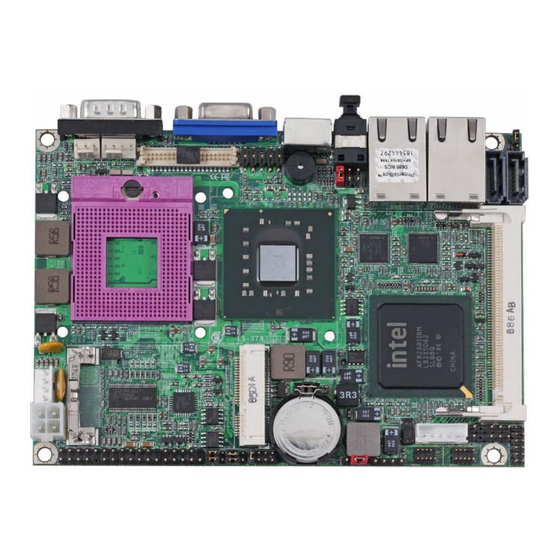
- Page 7 Chapter 1 <Introduction> 1.1 <Product Overview> LS-373, the new generation of the 3.5” Miniboard, supports Intel Penryn Processors for 667/800/1066 MHz front side bus and features Intel GM45 and ICH9M chipset, integrated GMA X4500 graphics, One DDR3 SO-DIMM memory, REALTEK High Definition Audio, two Serial ATA and two Intel Gigabit LAN.
- Page 8 LS-373 User’s Manual 1.2 <Product Specification> General Specification Form Factor 3.5” Miniboard Support Intel Core 2 Duo Processor Package type: Micro-FCPGA478 Front side bus: 667/800/1066 MHz L2 Cache: All specification depend on the CPU. (1M/2M/3M/4M/6M) Memory One DDRIII 800/1066MHz up to 4GB...
- Page 9 LS-373 User’s Manual 1.3 <Mechanical Drawing > TOP:...
- Page 10 LS-373 User’s Manual Bot:...
- Page 11 LS-373 User’s Manual 1.4 <Block Diagram> Intel Core 2 Duo Processor Front side bus: 667/800/1066 MHz 1 x VGA Interface Intel GMA X4500 1 x LVDS & HDTV 1 x 204-pin DDR3 SO-DIMM GM45 800/1066 MHz up to 1 x Mini PCI socket...
- Page 12 LS-373 User’s Manual Chapter 2 <Hardware Setup> 2.1 <Connector Location> CN_HDTV CN_LVDS SATA2 SATA1 SYSFAN CPUFAN MINIPCI MINI_CARD DC_OUT CN_INV CN_USB2 CN_USB1 JFRNT DC_IN CD_IN CN_DIO CN_COM2 CN_IR CN_AUDIO CN_SMBUS...
- Page 13 LS-373 User’s Manual SO-DIMM 1.24’ RJ45_1 RJ45_2 SPDIF COM1...
- Page 14 LS-373 User’s Manual 2.2 <Jumper Location & Reference> Jumper Function JRTC CMOS Operating/Clear Setting JVLCD Panel Voltage Setting Power mode select JCSEL1 RS-232 RS422 RS485 Setting / Setting CN_COM2 CN_IR IrDA JCSEL2 Jumper: JAT Type: onboard 3-pin header Power Mode...
- Page 15 LS-373 User’s Manual 2.3 <Connector Reference> 2.3.1 <Internal Connectors> Connector Function Remark Socket 478 for socket-P CPU SO-DIMM 204-pin DDR3 SO-DIMM socket SATA1/2 7-pin Serial ATA connector DC_IN DC 12V input connector DC_OUT 4-pin power output connector CN_AUDIO 5 x 2-pin audio connector...
- Page 16 LS-373 User’s Manual 2.4 <CPU and Memory Setup> 2.4.1 <CPU Setup> The board comes with the socket 478 for Intel Core 2 Duo socket-P Processor 667/800/1066 MHz of front side bus and L2 Cache: All specification depend on the CPU (1M/2M/3M/4M/6M). Please follow the instruction to install the CPU properly.
- Page 17 LS-373 User’s Manual 2.4.2 <Memory Setup> The board provides one 204-pin DDR3 SO-DIMM to support 800/1066MHz DDR3 SO-DIMM memory module up to 4GB. SO-DIMM...
- Page 18 LS-373 User’s Manual 2.5 <CMOS Setup> The board’s data of CMOS can be setting in BIOS. If the board refuses to boot due to inappropriate CMOS settings, here is how to proceed to clear (reset) the CMOS to its default values.
- Page 19 LS-373 User’s Manual 2.6 <Serial ATA Interface> Based on Intel ICH9M, the board provides two Serial ATAII interfaces with up to 300MB/s of transfer rate. SATA 2/1...
- Page 20 LS-373 User’s Manual 2.7 <Ethernet Interface> The board integrates with two Intel 82574L Gigabit Ethernet controllers. The Intel Gigabit Ethernet supports triple speed of 10/100/1000Base-T, with IEEE802.3 compliance and Wake-On-LAN supported. RJ45_2/1...
- Page 21 LS-373 User’s Manual 2.8 <Onboard Display Interface> Based on Intel GM45 chipset with built-in GMA (Graphic Media Accelerator) X4500 graphics, the board provides one DB15 connector on real external I/O port, and one 40-pin LVDS interface with 5-pin LCD backlight inverter connector. The board provides dual display function with clone mode and extended desktop mode for VGA, LVDS, and HDTV.
- Page 22 LS-373 User’s Manual 2.8.2 <Digital Display> The board provides one 40-pin LVDS connector for 18/24-bit single/dual channel panels, supports up to 1920 x 1200 (UXGA) resolution, with one LCD backlight inverter connector and one jumper for panel voltage setting. CN_LVDS...
- Page 23 LS-373 User’s Manual Connector: CN_INV Connector: JVLCD Type: 5-pin LVDS Power Header Type: 6-pin Power select Header Description Description +12V LCDVCC (3.3V) Reserved (Note) LCDVCC (5V) LCDVCC (12V) Default: 1-2 ENABKL Note: Reserved for MB internal test Please treat it as NC.
- Page 24 LCD Installation Guide: 1. Preparing the LS-373, LCD panel and the backlight inverter. 2. Please check the datasheet of the panel to see the voltage of the panel, and set the jumper JVLCD to +12V or +5V or +3.3V.
- Page 25 LS-373 User’s Manual After setup the devices well, you need to select the LCD panel type in the BIOS. The panel type mapping is list below: BIOS panel type selection form (BIOS Version:1.0) 18-bit Single channel 24-bit Dual channel Output format...
- Page 26 LS-373 User’s Manual 2.8.3 <HDTV Interface> The board provides HDTV interface with Intel GM45, support PAL and NTSC of TV system, and display (clone or extended desktop) function with CRT, LVDS. Connector: CN_HDTV Connector type: 10-pin header HDTV connector (pitch = 2.54mm)
- Page 27 LS-373 User’s Manual 2.9 <Integrated Audio Interface> The board integrates onboard audio interface with REALTEK ALC888 codec, with Intel next generation of audio standard as High Definition Audio, it offers more sound and other advantages than former AC’97 audio compliance.
- Page 28 LS-373 User’s Manual Connector: CN_AUDIO Type: 10-pin (2 x 5) header (pitch = 2.54x1.27 mm) Description Description MIC_L Ground MIC_R Reserve Speaker_R MIC Detect SENSE Speaker_L Speaker Detect Connector: CD_IN Type: 4-pin header (pitch = 2.54mm) Description CD – Left...
- Page 29 LS-373 User’s Manual 2.10 <GPIO Interface> The board provides a programmable 8-bit digital I/O interface; you can use this general purpose I/O port for system control like POS (Point-Of-Sale) or KIOSK (Public Information Booth). Connector: CN_DIO Type: 12-pin (6 x 2) header (pitch = 2.0mm)
- Page 30 LS-373 User’s Manual 2.11 <Power Supply> 2.11.1 <Power Input> The board requires onboard 4-pin DC-input connector voltage, for the input current, please take a reference of the power consumption report on appendix. Connector: DC_IN Type: 4-pin DC power connector for +12V/7A...
- Page 31 LS-373 User’s Manual 2.12 <Switch and Indicator> The JFRNT provides front control panel of the board, such as power button, reset and beeper, etc. Please check well before you connecting the cables on the chassis. Connector: JFRNT Type: onboard 14-pin (2 x 7) 2.54-pitch header...
- Page 32 LS-373 User’s Manual Chapter 3 <System Setup> 3.1 <Audio Configuration> The board integrates Intel® ICH9M with REALTEK® ALC888 codec. It can support 2-channel sound under system configuration. Please follow the steps below to setup your sound system. Install REALTEK HD Audio driver.
- Page 33 LS-373 User’s Manual 3.2 <Display Properties Setting> Based on Intel GM45 GMCH with GMA X4500 (Graphic Media Accelerator), the board supports two DACs for display device as different resolution and color bit. Please install the Intel Graphic Driver before you starting setup display devices.
- Page 34 LS-373 User’s Manual 3. This setup options can let you define each device settings. Click Monitor to setup the CRT monitor for Colors, Resolution and Refresh Rate Click Intel(R) Dual Display Clone setup dual display mode as same screen...
- Page 35 LS-373 User’s Manual Chapter 4 <BIOS Setup> The motherboard uses the Award BIOS for the system configuration. The Award BIOS in the single board computer is a customized version of the industrial standard BIOS for IBM PC AT-compatible computers. It supports Intel x86 and compatible CPU architecture based processors and computers.
- Page 36 LS-373 User’s Manual (This page is left for blank)
- Page 37 LS-373 User’s Manual Appendix A <I/O Port Pin Assignment> A.1 <Serial ATA Port> Connector: SATA1/2 Type: 7-pin wafer connector GND RSATA_TXP1 RSATA_TXN1 GND RSATA_RXN1 RSATA_RXP1 GND A.2 <IrDA Port> Connector: CN_IR Type: 5-pin header for SIR Port Description Ground JCSEL1 must jump to “SIR”...
- Page 38 LS-373 User’s Manual A.3 <SMBUS Port> Connector: CN_SMBUS Type: 5-pin header Description SMBDATA SMBCLK CN_SMBUS A.4 <Serial Port 1> Connector: COM1 Type: 9-pin D-sub male connector Description Description Ground...
- Page 39 LS-373 User’s Manual A.5 <Serial Port 2> Connector: CN_COM2 Type: 9-pin header connector (pitch = 2.54x1.27 mm) Description Description DCD/422TX-/485- RX/422TX+/485+ TX/422RX+ DTR/422RX- Ground...
- Page 40 LS-373 User’s Manual RS-232 & RS-422 & RS-485 Setting: Function JCSEL1 JCSEL2 RS-422 RS-485 RS-232 COM1 CN_COM2 JCSEL1 JCSEL2...
- Page 41 LS-373 User’s Manual A.6 <VGA Port> Connector: CRT Type: 15-pin D-sub female connector on bracket Description Description Description Ground GREEN Ground DDCDA BLUE Ground HSYNC VSYNC Ground Ground DDCCLK A.7 <LAN Port> Connector: RJ45_1/2 Type: RJ45 connector with LED on bracket...
- Page 42 LS-373 User’s Manual Appendix B <Flash BIOS> B.1 <Flash Tool> The board is based on Award BIOS and can be updated easily by the BIOS auto flash tool. You can download the tool online at the address below: http://www.phoenix.com/en/home/ http://www.commell.com.tw/Support/Support_SBC.htm File name of the tool is “awdflash.exe”, it’s the utility that can write the data into the...
- Page 43 LS-373 User’s Manual Appendix C <System Resources> C.1 <Direct memory access (DMA)> C.2 <Input/output (IO)>...
- Page 44 LS-373 User’s Manual...
- Page 45 LS-373 User’s Manual C.3 <Interrupt request (IRQ)>...
- Page 46 LS-373 User’s Manual C.4 <Memory>...
- Page 47 LS-373 User’s Manual Appendix D <Programming GPIO’s> The GPIO’s can be programmed with the MSDOS debug program using simple IN/OUT commands. The following lines show an example how to do this. GPIO0...GPIO7 bit0…bit7 -o 2E 87 ;Enter configuration -o 2E 87...
- Page 48 LS-373 User’s Manual Appendix E <Programming Watchdog Timer> The watchdog timer makes the system auto-reset while it stops to work for a period. The integrated watchdog timer can be setup as system reset mode by program. Time-out Value Range - 1 to 255...
- Page 49 Taiwan Commate Computer Inc. Address 19F, No. 94, Sec. 1, Xintai 5th Rd., Xizhi Dist New Taipei City, Taiwan +886-2-26963909 +886-2-26963911 Website http://www.commell.com.tw E-Mail info@commell.com.tw (General Information) tech@commell.com.tw (Technical Support) Commell is a brand name of Taiwan Commate Computer Inc.
Need help?
Do you have a question about the LS-373 and is the answer not in the manual?
Questions and answers