Table of Contents
Advertisement
Quick Links
Advertisement
Table of Contents

Related Manuals for Commell LE-370


Summary of Contents for Commell LE-370
- Page 1 LE-370/LE-370Z 3.5 Inches Embedded Miniboard User’s Manual Edition: 1.0 2005/6/13...
- Page 2 LE-370 User’s Manual Copyright Copyright 2004 - 2005. All rights reserved. This document is copyrighted and all rights are reserved. The information in this document is subject to change without prior notice to make improvements to the products. This document contains proprietary information and protected by copyright. No part of this document may be reproduced, copied, or translated in any form or any means without prior written permission of the manufacturer.
-
Page 3: Packing List
LE-370 User’s Manual Packing List: Please check the package before you starting setup the system Hardware: LE-370/LE-370Z motherboard x 1 Cable Kit: 44-pin 40-pin 44-pin 44-pin ATA33 IDE Cable x 1 CPU Cooler (LE-370 only) COM port & Printer Port Cable x 1 USB Cable x 1 PS/2 keyboard &... - Page 4 LE-370 User’s Manual Index Chapter 1 <Introduction> .................. 7 1.1 <Product Overview>................7 1.2 <Product Specification> ................ 8 1.3 <Mechanical Drawing>................ 10 1.4 <Block Diagram>................. 11 Chapter 2 <Hardware Setup>................13 2.1 <Connector Location>................. 13 2.2 <Jumper Location & Reference> ............14 2.3 <Connector Reference>..............
- Page 5 LE-370 User’s Manual 2.13 <Switch & Indicator> ................. 31 Chapter 3 <System Setup> ................33 3.1 <Display Configuration>..............33 Chapter 4 <BIOS Setup> ................. 35 Appendix A <I/O Port Pin Assignment>............37 A.1 <IDE Port> ..................37 A.2 <Floppy Port> ..................38 A.3 <IrDA Port>...
- Page 6 LE-370 User’s Manual (This Page is Left For Blank)
-
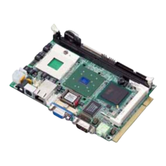
Page 7: Product Overview
18/24-bit LVDS LCD interface The board provides onboard 18/24-bit LVDS LCD interface, supports up to 1600 x 1200 of UXGA high resolution for LE-370, and up to 1400 x 1050 for LE-370Z. Flexible Extension Interfaces The board provides one Mini-PCI socket for wireless LAN module, video capture card and IEEE1394 add-on card. -
Page 8: Product Specification
LE-370 User’s Manual Introduction 1.2 <Product Specification> General Specification LE-370 LE-370Z Form Factor 3.5 inches Embedded Miniboard Intel Pentium M/Celeron M Embedded Intel Celeron M Package: FC-PGA478 Ratio: 600MHz FSB: 400/533MHz FSB: 400MHz Memory 1 x 184-pin DDR 266/333 1 x 184-pin DDR 200/266... - Page 9 LE-370 User’s Manual Introduction Ethernet Interface Controller Intel 82562ET PHY Type 10Base-T / 100Base-TX auto-switching Fast Ethernet Full duplex, IEEE802.3U compliant Connector External RJ45 connectors with LED on rear I/O panel Audio Interface Chipset REALTEK ALC201A Interface 2 channel 3D audio with Line-in, Line-out and MIC-in...
-
Page 10: Mechanical Drawing
LE-370 User’s Manual Introduction 1.3 <Mechanical Drawing> Mechanical Drawing... -
Page 11: Block Diagram
LE-370 User’s Manual Introduction 1.4 <Block Diagram> Intel Pentium M processor with FC-PGA2/FC-BGA2 CRT/LCD Monitor LVDS 1 x 184-pin DDR DIMM up to 1GB 852GME/GM 2 x USB2.0 Ports 82562ET PHY ICH4 AC97 Codec Mini-PCI 2 x Serial ports BIOS... - Page 12 LE-370 User’s Manual (This Page is Left for Blank)
-
Page 13: Connector Location
LE-370 User’s Manual Hardware Setup Chapter 2 <Hardware Setup> 2.1 <Connector Location> CN_COM2 AUDIO COM1 CDIN CN_INV RJ45 DC_IN CN_12V CN_USB CN_AUDIO CN_DIO CN_SPWR CPUFAN CN_LVDS SYSFAN MINIPCI DIMM CN_IR IDE1 JFRNT Connector Location... -
Page 14: Jumper Location & Reference
LE-370 User’s Manual Hardware Setup 2.2 <Jumper Location & Reference> Jumper Function JRTC CMOS Operating/Clear Setting JVLCD LCD panel voltage setting JVLCD JRTC Jumper Location & Reference... -
Page 15: Connector Reference
LE-370 User’s Manual Hardware Setup 2.3 <Connector Reference> 2.3.1 <Internal Connector> Connector Function Remark DIMM 184-pin DDR SDRAM DIMM Standard IDE1 44-pin primary IDE connector Standard 26-pin slim type floppy connector Standard CN_12V 4-pin DC input connector Standard CDIN 4-pin CD-ROM audio input connector... -
Page 16: Cpu & Memory Setup
LE-370 supports onboard socket479 for Intel Pentium M/Celeron M processors with FC-PGA478 package, 400/533MHz of front side bus; LE-370Z integrates onboard Intel Celeron M 600MHz processor with 400MHz of front side bus. For LE-370 please follow the instruction to install the CPU properly. -
Page 17: Memory
LE-370 User’s Manual Hardware Setup 2.4.2 <Memory> LE-370 supports DDR266/333 up to 1GB with ECC; LE-370Z supports DDR200/266 up to 1GB with unbuffered, non-ECC memory module. DIMM 104-pin 80-pin Please check the pin number to match the socket side well before installing memory module. -
Page 18: Cpu Cooler Installation
LE-370 User’s Manual Hardware Setup 2.4.3 <CPU Cooler Installation> The LE-370 provides one CPU cooler; please follow the instruction below to finish the installation. The LE-370Z comes with a heat sink on embedded processor, no fan is required. 2. Put the cooler on the socket 1. -
Page 19: Cmos Setup
LE-370 User’s Manual Hardware Setup 2.5 <CMOS Setup> The board’s data of CMOS can be setting in BIOS. If the board refuses to boot due to inappropriate CMOS settings, here is how to proceed to clear (reset) the CMOS to its default values. -
Page 20: Enhanced Ide & Cf Interface
LE-370 User’s Manual Hardware Setup 2.6 <Enhanced IDE & CF interface> The board supports one UltraDMA133 IDE interface, and one CompactFlash Type 1 socket with secondary IDE mode, the 44-pin IDE1 connector can support up to 2 ATAPI devices through IDE cable. -
Page 21: Floppy Port
LE-370 User’s Manual Hardware Setup 2.7 <Floppy Port> The board provides a slim type floppy port; please use the 26-pin ribbon cable in the package to connect the floppy device. Lift up the brown plastic bar Slot the cable in (Blue paste for... -
Page 22: Ethernet Interface
LE-370 User’s Manual Hardware Setup 2.8 <Ethernet Interface> The board integrates Ethernet controller with Intel 82562ET PHY, full compliance with IEEE 802.3u 100Base-T specifications and IEEE 802.3x Full Duplex Flow Control, the board supports Wake-Up-On-LAN by BIOS configurable. RJ45 For Wake Up On LAN function, please enable this option in the BIOS... -
Page 23: Onboard Display Interface
VGA display interface, and one 18/24-bit LVDS LCD interface, supports up to 1600 x 1200 of resolution for LE-370 (with 852GME) and 1400 x 1050 for LE-370Z (with 852GM). The two display interfaces can be set for dual display with extended desktop mode or clone mode. -
Page 24: Digital Display Interface
LE-370 User’s Manual Hardware Setup 2.9.2 <Digital Display Interface> The onboard digital display interface comes with a 40-pin header connector to provide 18/24-bit LVDS LCD interface, and one backlight inverter connector for powering and enable/disable control, the jumper JVLCD is to set the panel voltage. - Page 25 LE-370 User’s Manual Hardware Setup Connector: CN_INV Connector: JVLCD Type: 5-pin LVDS Power Header Type: 3-pin Power select Header Description Description +12V LCDVCC VCC3 ENABKL Connector: CN_LVDS Type: onboard 40-pin connector for LVDS connector Connector model: HIROSE DF13-40S Signal Signal...
- Page 26 LCD Installation Guide: Preparing the LE-370, LCD panel and the backlight inverter. Please check the datasheet of the panel to see the voltage of the panel, and set the jumper JVOLT to +5V or +3.3V.
- Page 27 1400 x 1050 Dual Channel @ 122Mhz 14 1920 x 1080 Dual Channel 1600 x 1200 Dual Channel 1280 x 768 1024 x 768 Dual Channel Notice: Panel type 7, 11 and 14 are only supported by LE-370, not for LE-370Z Onboard Display Interface...
-
Page 28: Onboard Audio Interface
LE-370 User’s Manual Hardware Setup 2.10 <Onboard Audio Interface> The board integrates onboard AC97 audio with REALTEK ALC201A, supports 18-bit ADC and DAC resolution, and Line-out, Line-in and MIC-in input/output interfaces. Connector: CN_AUDIO Type: 10-pin (2 x 5) 1.27mm x 2.54mm-pitch header... -
Page 29: Gpio Interface
LE-370 User’s Manual Hardware Setup 2.11 <GPIO Interface> The board offers 8-bit digital I/O to customize its configuration to your control needs. For example, you may configure the digital I/O to control the opening and closing of the cash drawer or to sense the warning signal from a tripped UPS. -
Page 30: Power Supply & Fan
LE-370 User’s Manual Hardware Setup 2.12 <Power Supply & Fan> 2.12.1 <Power Input> The board requires DC 12V input with onboard DC jack or 4-pin 12V DC connector. Connector: CN_12V Type: 4-pin standard ATX2.0 +12V power connector Description Description Ground... -
Page 31: Switch & Indicator
LE-370 User’s Manual Hardware Setup 2.13 <Switch & Indicator> The JFRNT provides front control panel of the board, such as power button, reset and beeper, etc. Please check well before you connecting the cables on the chassis. Connector: JFRNT Type: onboard 14-pin (2 x 7) 2.54-pitch header... - Page 32 LE-370 User’s Manual (This Page is Left for Blank)
-
Page 33: Chapter 3
LE-370 User’s Manual System Setup Chapter 3 <System Setup> 3.1 <Display Configuration> The board provides onboard VGA with DB15 analog display interface, and LVDS LCD interface for digital display, when connecting two display devices, you can enable dual display function with clone mode or extended desktop mode. - Page 34 LE-370 User’s Manual System Setup Please select Devices for advanced device setting. Single Display Device Setting Dual Display Device Setting When you set dual display clone mode, you’ll see the same screen display on two devices. When you set the dual display for extended desktop mode, you can have the independent desktop on the second device.
-
Page 35: Chapter 4
LE-370 User’s Manual BIOS Setup Chapter 4 <BIOS Setup> The single board computer uses the Award BIOS for the system configuration. The Award BIOS in the single board computer is a customized version of the industrial standard BIOS for IBM PC AT-compatible computers. It supports Intel x86 and compatible CPU architecture based processors and computers. - Page 36 LE-370 User’s Manual (This Page is Left for Blank)
-
Page 37: Appendix A
LE-370 User’s Manual I/O Port Pin Assignment Appendix A <I/O Port Pin Assignment> A.1 <IDE Port> Connector: IDE1 Type: 44-pin (22 x 2) box header Description Description Reset Ground Ground Ground -IOW Ground -IOR Ground IORDY Ground DACK Ground IRQ14... -
Page 38: A.2
LE-370 User’s Manual I/O Port Pin Assignment A.2 <Floppy Port> Connector: FDD Type: 26-pin connector Description Description INDEX DRV0 DSKCHG DRV1 MTR1 MTR0 STEP Ground WRITE DATA Ground WRITE GATE TRACK 0 WRPTR Ground RDATA- Ground A.3 <IrDA Port> Connector: CN_IR... -
Page 39: A.5
LE-370 User’s Manual I/O Port Pin Assignment A.5 <Serial Port> Connector: COM1 Type: 9-pin D-sub male connector on bracket Description Description Ground Connector: CN_COM2 Type: 10-pin (2 x 5) 1.27mm x 2.54mm-pitch header Description Description Ground A.6 <LAN Port> Connector: RJ45... - Page 40 LE-370 User’s Manual (This Page is Left for Blank)
-
Page 41: Appendix B
LE-370 User’s Manual Flash BIOS Appendix B <Flash BIOS> B.1 BIOS Auto Flash Tool The board is based on Award BIOS and can be updated easily by the BIOS auto flash tool. You can download the tool online at the address below: http://www.award.com... - Page 42 LE-370 User’s Manual (This Page is Left for Blank)
-
Page 43: Appendix C
LE-370 User’s Manual Hardware Test Appendix C <Hardware Test> C.1 <Power Consumption Test> Hardware Board LE-370Z Intel® Celeron® M 600MHz Memory Infineon DDR333 512MB x1 Hitachi IC25N080ATMR04 80GB CDROM SDR-038 4x DVD-ROM (not counted) Power Supply SEVENTEAM ST-402HLP Software Windows XP SP1 English Version... -
Page 44: Contact Information
Taiwan Commate Computer Inc. Address 8F, No. 94, Sec. 1, Shin Tai Wu Rd., Shi Chih Taipei Hsien, Taiwan +886-2-26963909 +886-2-26963911 Website h ttp://www.commell.com.tw E-Mail i nfo@commell.com.tw (General Information) t ech@commell.com.tw (Technical Support) Commell is our trademark of industrial PC division...
Need help?
Do you have a question about the LE-370 and is the answer not in the manual?
Questions and answers