Advertisement
Quick Links
Advertisement

Related Manuals for Commell LS-371E


Summary of Contents for Commell LS-371E
- Page 1 LS-371 3.5 inch Miniboard User’s Manual Edition 1.4 2010/11/1...
- Page 2 Trademark All trademarks are the property of their respective holders. Any questions please visit our website at http://www.commell.com.tw...
-
Page 3: Packing List
LS-371 User’s Manual Packing List Please check the package before you starting setup the system Hardware: LS-371 Miniboard x 1 Cable Kit: 44-pin 40-pin DC Power Cable x 1 44-pin ATA33 IDE Cable x1 SATA Cable x 2 PS/2 keyboard & mouse cable x 1 SATA Power Cable x 1 Audio Port Cable x 1 1 to 3 power output cable... - Page 4 LS-371 User’s Manual Index Chapter 1 <Introduction> ..................7 1.1 <Product Overview>................. 7 1.2 <Product Specification> ................8 1.3 <Mechanical Drawing>................10 1.4 <Block Diagram>..................11 Chapter 2 <Hardware Setup>................12 2.1 <Connector Location>................12 2.2 <Jumper Reference> ................14 2.3 <Connector Reference>.................
- Page 5 LS-371 User’s Manual 2.14.1 <Power Input> ................35 2.14.2 <Power Output> ............... 36 2.14.3 <Fan Connector>..............36 2.15 <Indicator and Switch>................. 37 Chapter 3 <System Configuration>..............38 3.1 <Video Memory Setup> ................. 38 3.2 <Audio Configuration> ................40 Chapter 4 <BIOS Setup> ..................42 Appendix A <I/O Port Pin Assignment>...
- Page 6 LS-371 User’s Manual (The Page is Left For Blank)
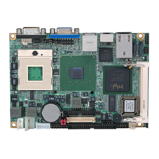
- Page 7 LS-371 User’s Manual Chapter 1 <Introduction> 1.1 <Product Overview> LS-371 is the 3.5 inch miniboard, with supporting Intel Core 2 Dual/Core Dual/ Core Solo processors for 533/667MHz front side bus, Intel 945GM(E) and ICH7-M chipset, integrated GMA950 graphics, DDR2 SO-DIMM memory, Realtek AC97 Audio, Serial ATA and one Intel 82573L Gigabit LAN.
- Page 8 LS-371 User’s Manual 1.2 <Product Specification> General Specification Form Factor 3.5 inch miniboard Intel® Core 2 Dual/Core Dual/Core Solo processor Package type: Micro- FCPGA478 Front side bus: 533/667MHz Memory 1 x 200-pin DDR2 533/667MHz SO-DIMM SDRAM up to 2GB Unbufferred, none-ECC memory supported only Chipset Intel®...
- Page 9 Support Intel Core 2 Dual/Core Dual/ Core solo processor with onboard VGA, HDTV, DVI, LVDS, Audio, SATA, Giga LAN, USB2.0, CF, GPIO, Mini PCI, FDD The specifications may be different as the actual production. For further product information please visit the website at http://www.commell.com.tw...
- Page 10 LS-371 User’s Manual 1.3 <Mechanical Drawing>...
- Page 11 LS-371 User’s Manual 1.4 <Block Diagram> Intel Yonah Processor 1 x 200-pin SO-DIMM DDR2 533/677MHz Intel GMA950 Graphics up to 2GB HDTV&LVDS&DVI 2 x SATA CompactFlash&IDE AC97 ALC655 4 x USB2.0 ports Intel 82537L 1 x GLAN W83627THG 2 x Serial ports 8-bit GPIO 1 x IrDA BIOS...
- Page 12 LS-371 User’s Manual Chapter 2 <Hardware Setup> 2.1 <Connector Location> CN_LVDS CN_USB1 JFRNT CN_INV DC_IN SYSFAN DC_OUT CN_IR CN_DVI MINIPCI CDIN CN AUDIO CPUFAN CN_DIO SATA1/2 CN_HDTV CN_COM2...
- Page 13 LS-371 User’s Manual DDRII RJ45 COM1...
- Page 14 LS-371 User’s Manual 2.2 <Jumper Reference> Jumper Function JRTC CMOS Operating/Clear Setting JVLCD LCD Panel Voltage Setting AT Mode JCSEL1/2 COM2 RS232/422/485 mode setting JVLCD JRTC JCSEL1 JCSEL2...
- Page 15 LS-371 User’s Manual 2.3 <Connector Reference> 2.3.1 <Internal Connector> Connector Function Remark DDRII 200 -pin DDR2 SO-DIMM SDRAM slot Standard 44-pin primary IDE connector Slim SATA1/2 7-pin Serial ATA connector Standard CN_AUDIO 5 x 2-pin audio connector Slim CDIN 4-pin CD-ROM audio input connector Standard CN_DIO 6 x 2-pin digital I/O connector...
- Page 16 LS-371 User’s Manual 2.4 <CPU and Memory Setup> 2.4.1< CPU> The board comes with the socket479 for Intel Core 2 Dual/Core Dual /Core solo processor, it supports new generation of Intel Core 2 Dual/Core Dual /Core solo processor with 533/667MHz of front side bus and 2MB L2 cache. Please follow the instruction to install the CPU properly.
- Page 17 LS-371 User’s Manual 2.4.2 <Memory> T The board provides one 200-pin DDR2 SO-DIMM to support DDR2 533/667 memory modules up to 2GB of capacity. Non-ECC, unbuffered memory is supported only. DDRII...
- Page 18 LS-371 User’s Manual 2.5 <CMOS&ATX Setup> The board’s data of CMOS can be setting in BIOS. If the board refuses to boot due to inappropriate CMOS settings, here is how to proceed to clear (reset) the CMOS to its default values. Jumper: JRTC Type: Onboard 3-pin jumper JRTC...
- Page 19 LS-371 User’s Manual 2.6 <Enhanced IDE & CF Interface> The board has one Ultra DMA33 IDE interface to support up to 2 ATAPI devices, and one Compact Flash Type II socket on the solder side.
- Page 20 LS-371 User’s Manual 2.7 <Serial ATA Interface> Based on Intel ICH7-M, the board provides two Serial ATA interfaces with up to 150MB/s of transfer rate SATA1/2 2.8 <LAN Interface> The Intel 82573L supports triple speed of 10/100/1000Base-T, with IEEE802.3 compliance and Wake-On-LAN supported.
- Page 21 LS-371 User’s Manual 2.9 <Onboard Display Interface> Based on Intel 945GM(E) chipset with built-in GMA (Graphic Media Accelerator) 950 graphics, the board provides one DB15 connector on real external I/O port, and one 40-pin LVDS interface with 5-pin LCD backlight inverter connector. The board provides dual display function with clone mode and extended desktop mode for CRT and LCD and DVI and TV-out.
- Page 22 LS-371 User’s Manual 2.9.2 <Digital Display> The board provides one 40-pin LVDS connector for 18-bit dual channel panels, supports up to 1600 x 1200 (UXGA) of resolution, with one LCD backlight inverter connector and one jumper for panel voltage setting CN_LVDS CN_INV JVLCD...
- Page 23 LS-371 User’s Manual Connector: CN_INV Connector: JVLCD Type: 5-pin LVDS Power Header Type: 3-pin Power select Header Connector model: JST B5B-XH-A Description Description +12V VCC(5V) LCDVCC VCC3(3.3) ENABKL Connector: CN_LVDS Type: onboard 40-pin connector for LVDS connector Connector model: HIROSE DF13-40DP-1.25V Signal Signal LCDVCC...
- Page 24 LS-371 User’s Manual To setup the LCD, you need the component below: A panel with LVDS interfaces. An inverter for panel’s backlight power. A LCD cable and an inverter cable. For the cables, please follow the pin assignment of the connector to make a cable, because every panel has its own pin assignment, so we do not provide a standard cable;...
- Page 25 LS-371 User’s Manual 2.9.3 <DVI Interface > The board also comes with a DVI interface with Chrontel CH7307C for digital video interface. Connector: CN_DVI Connector type: 26-pin header connector (pitch = 2.00mm) Pin Number Assignment Pin Number Assignment TX1+ TX1- Ground Ground TXC+...
- Page 26 LS-371 User’s Manual 2.9.4<TV-out Interface> The board provides an HDTV interface with Intel 945GM(E), supports PAL and NTSC of TV system, and display (clone or extended desktop) function with CRT, LVDS and DVI. Connector: CN_HDTV Connector type: 10-pin header HDTV connector (pitch = 2.54mm) Pin Number Assignment Pin Number...
- Page 27 LS-371 User’s Manual To connect the TV set, please follow the diagram below to setup your system: YPrPb Component Cable (For HDTV)
- Page 28 LS-371 User’s Manual After setup the devices well, you need to select the LCD panel type in the BIOS. The panel type mapping is list below: BIOS panel type selection form 18 bits Single channel 24 bits Dual channel Output format Output format 640 x 480 1024 x 768...
- Page 29 LS-371 User’s Manual 2.10 <Onboard Audio Interface> The board provides the onboard AC97 5.1-channel audio interface with Realtek ALC655 Connector: CN_AUDIO Type: 10-pin (2 x 5) 1.27mm x 2.54mm-pitch header Description Description LIN_L Ground LIN_R MIC 2 MIC 2 Ground FRONTL FRONTR Ground...
- Page 30 LS-371 User’s Manual 2.11 <USB2.0 Interface> Based on Intel ICH7-M , the board provides 4 USB2.0 ports. The USB2.0 interface provides up to 480Mbps of transferring rate. Interface USB2.0 Controller ICH7-M Transfer Rate Up to 480Mb/s Output Voltage 500mA CN_USB CN_IR...
- Page 31 LS-371 User’s Manual Connector: CN_IR Type: 5-pin header for SIR Port Description IRRX Ground IRTX Connector: CN_USB Type: 10-pin (5 x 2) header for USB Port Description Description Data0- Data1- Data0+ Data1+ Ground Ground Ground PS: The USB2.0 will be only active when you connecting with the USB2.0 devices, if you insert an USB1.1 device, the port will be changed to USB1.1 protocol automatically.
- Page 32 LS-371 User’s Manual 2.12 <GPIO Interface> The board provides a programmable 8-bit digital I/O interface; you can use this general purpose I/O port for system control like POS or KIOSK. Connector: CN_DIO Type: onboard 2 x 6-pin header, pitch=2.0mm Description Description Ground Ground...
- Page 33 LS-371 User’s Manual 2.13 <Serial Port Jumper Setting > The board provides three RS232 serial ports, with jumper selectable RS422/485 for COM2. Connector: CN_COM2 Type: 10-pin (5 x 2) 1.27mm x 2.54mm-pitch header for COM2 Description Description DCD/422TX-/485- RXD/422TX+/485+ TXD/422RX+ DTR/422RX- JCSEL1 JCSEL2 RS-232...
- Page 34 LS-371 User’s Manual CN_COM2 JCSEL1 JCSEL2 COM1...
- Page 35 LS-371 User’s Manual 2.14 <Power and Fan Connector> The board requires DC input with 3-pin hear, the input voltage range is from 8V to 24V, for the input current, please take a reference of the power consumption report on appendix. 2.14.1 <Power Input>...
- Page 36 LS-371 User’s Manual 2.14.2 <Power Output> Connector: DC_OUT Type: 4-pin connector for +5V/+12V output Pin Description Pin Description Pin Description Pin Description +12V Ground Ground Note: Maximum output current 12V/3A, 5V/3A 2.14.3 <Fan Connector> Connector: SYSFAN Type: 3-pin fan wafer connector Description Description Description...
- Page 37 LS-371 User’s Manual 2.15 <Indicator and Switch> The JFRNT provides front control panel of the board, such as power button, reset and beeper, etc. Please check well before you connecting the cables on the chassis. Connector: JFRNT Type: onboard 14-pin (2 x 7) 2.54-pitch header Function Signal Signal...
- Page 38 LS-371 User’s Manual Chapter 3 <System Configuration> 3.1 <Video Memory Setup> Based on Intel® 945GM(E) chipset with GMA (Graphic Media Accelerator) 950, the board supports Intel® DVMT (Dynamic Video Memory Technology) 3.0, which would allow the video memory to be allocated up to 224MB. To support DVMT, you need to install the Intel GMA 950 Driver with supported OS.
- Page 39 LS-371 User’s Manual Notice: The On-Chip Frame Buffer Size would be included in the Fixed Memory. Please select the memory size according to this table. On-Chip Fixed DVMT Total System Frame Memory Memory Graphic Memory Buffer Size Size Size Memory 32MB 32MB 32MB...
- Page 40 LS-371 User’s Manual 3.2 <Audio Configuration> The board provides 5.1 channel audio interface with driver installed, please install the Realtek ALC655 audio driver in the CD before getting start to enjoy the 5.1 channel sound system. Install REALTEK AC97 Audio driver. Lunch the control panel and Sound Effect Manager.
- Page 41 LS-371 User’s Manual (This Page is Left for Blank)
- Page 42 LS-371 User’s Manual Chapter 4 <BIOS Setup> The motherboard uses the Award BIOS for the system configuration. The Award BIOS in the single board computer is a customized version of the industrial standard BIOS for IBM PC AT-compatible computers. It supports Intel x86 and compatible CPU architecture based processors and computers.
- Page 43 LS-371 User’s Manual Appendix A <I/O Port Pin Assignment> A.1 <IDE Port> Connector: IDE Type: 44-pin (22 x 2) box header Description Description Reset Ground Ground Ground IOW-/STOP Ground IOR-/HDMARDY Ground IORDY/DDMARDY Ground DACK- Ground ASP1 Ground Ground Ground...
- Page 44 LS-371 User’s Manual A.2 <IrDA Port> Connector: CN_IR Type: 5-pin header for SIR Port Description IRRX Ground IRTX A.3 < CRT Port > Connector: CRT Type: 15-pin D-sub female connector on panel Description Description Description Ground GREEN Ground 5VCDA BLUE Ground HSYNC LVGA5V...
- Page 45 LS-371 User’s Manual A.5 <Serial Port> Connector: COM1 Type: 9-pin D-sub male connector on rear panel Description Description Ground A.6 <LAN Port> Connector: RJ45 Type: RJ45 connector with LED on rear panel Description...
- Page 46 The board is based on Award BIOS and can be updated easily by the BIOS auto flash tool. You can download the tool online at the address below: http://www.award.com http://www.commell.com.tw/support/support.htm File name of the tool is “awdflash.exe”, it’s the utility that can write the data into the BIOS flash ship and update the BIOS.
- Page 47 LS-371 User’s Manual Appendix C <System Resources> C1.<I/O Port Address Map>...
- Page 48 LS-371 User’s Manual C2. <Memory Address Map>...
- Page 49 LS-371 User’s Manual C3.<System IRQ Resources>...
- Page 50 LS-371 User’s Manual Appendix D <Programming GPIO’s> The GPIO can be programmed with the MSDOS debug program using simple IN/OUT commands.The following lines show an example how to do this. GPIO0…..GPIO7 bit0……bit7 -o 2E 87 ;enter configuration -o 2E 87 -o 2E 29 -o 2F 40 ;enable GPIO function...
- Page 51 LS-371 User’s Manual Appendix E <Watch Dog timer Setting > The watchdog timer makes the system auto-reset while it stops to work for a period. The integrated watchdog timer can be setup as system reset mode by program. Timeout Value Range - 1 to 255 - Second or Minute Program Sample...
- Page 52 LS-371 User’s Manual (This Page is Left for Blank)
-
Page 53: Contact Information
Taiwan Commate Computer Inc. Address 19F, No. 94, Sec. 1, Shin Tai Wu Rd., Shi Chih Taipei Hsien, Taiwan +886-2-26963909 +886-2-26963911 Website h ttp://www.commell.com.tw E-Mail i nfo@commell.com.tw (General Information) t ech@commell.com.tw (Technical Support) Commell is our trademark of industrial PC division...
Need help?
Do you have a question about the LS-371E and is the answer not in the manual?
Questions and answers