Table of Contents
Advertisement
Quick Links
Advertisement
Table of Contents

Related Manuals for Commell LS-573


Summary of Contents for Commell LS-573
- Page 1 LS-573 5.25” Embedded Miniboard User’s Manual Edition 1.02 2009/08/25...
- Page 2 LS-573 User’s Manual Copyright Copyright 2008, all rights reserved. This document is copyrighted and all rights are reserved. The information in this document is subject to change without prior notice to make improvements to the products. This document contains proprietary information and protected by copyright. No part of this document may be reproduced, copied, or translated in any form or any means without prior written permission of the manufacturer.
-
Page 3: Sata Cable X
LS-573 User’s Manual Packing List: Please check the package content before you starting using the board. Hardware: LS-573 Embedded Miniboard x 1 Cable Kit: SATA Cable x 2 Printer Port Cable x 1 USB Cable x 2 HD Audio Port Cable x 1... - Page 4 LS-573 User’s Manual HDTV cable x 1 (Optional) SDTV cable x 1 (Optional) Printed Matters: Driver CD x 1 (Including User’s Manual)
- Page 5 LS-573 User’s Manual Index Chapter 1 <Introduction> ......................7 1.1 <Product Overview>.............7 1.2 <Product Specification> ............8 1.3 <Mechanical Drawing> ............10 1.4 <Block Diagram> ...............11 Chapter 2 <Hardware Setup> ....................12 2.1 <Connector Location> ............12 2.2 <Jumper Location & Reference>........14 2.3 <Connector Reference> ............16 2.3.1 <Internal Connectors>...
- Page 6 LS-573 User’s Manual 3.1 <Audio Configuration> ............35 3.2 <Video Memory Setup> .............36 3.3 <Display Properties Setting>..........37 Chapter 4 <BIOS Setup>......................39 Appendix A <I/O Port Pin Assignment> ................41 A.1 <Serial ATA Port> ..............41 A.2 <IrDA Port> ...............41 A.3 <SMBUS Port>..............42 A.4 <Serial Port 2> ..............42 A.5 <Parallel Port>...
- Page 7 LS-573 User’s Manual (This page is left for blank)
-
Page 8: Chapter 1
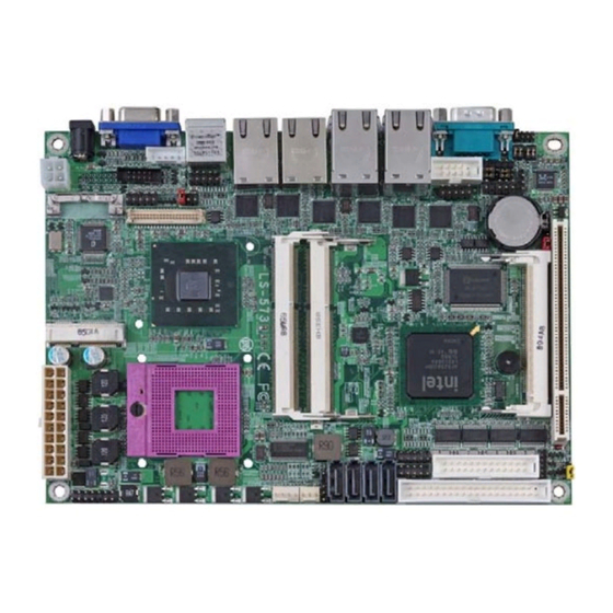
Chapter 1 <Introduction> 1.1 <Product Overview> LS-573 the new generation of the 5.25” Miniboard, supports Intel Penryn Processor for 667/800/1066 MHz front side bus and features Intel GM45 and ICH9M chipset, integrated GMA X4500 graphics, DDR3 memory, REALTEK ALC888 High Definition Audio, Serial ATA and six Intel Gigabit LAN. -
Page 9: Product Specification
LS-573 User’s Manual 1.2 <Product Specification> General Specification Form Factor 5.25 Inches Embedded Miniboard Support Intel Penryn Processor Package type: Micro-FCPGA478 (Socket-P) L2 Cache: All specification depend on the CPU. (1M/2M/3M/4M/6M) Front side bus: 667/800/1066 MHz Memory 2 x 800/1066MHz DDRIII 204-pin SO-DIMM up to 8GB Chipset Intel®... - Page 10 LS-573 User’s Manual Audio Interface Chipset Intel® ICH9M with Realtek ALC888 HD Audio Intel High Definition Audio compliance Interface 2 channels sound output Connector Internal 10-pin header for line-in/-out, MIC-in, 4-pin header for CD-IN Power and Environment Power Standard 20-Pin ATX power supply or 9V~24V DC Input...
-
Page 11: Mechanical Drawing
LS-573 User’s Manual 1.3 <Mechanical Drawing>... -
Page 12: Block Diagram
LS-573 User’s Manual 1.4 <Block Diagram> Intel Mobile Core 2 Duo Mobile Processor Intel GMA 4500MHD 2 x 204-pin DDR3 SO-DIMM HDTV & LVDS 800/1066MHz up to 4GB GM45 4 x Serial ATA ports 8 x USB2.0 ports HD Audio... -
Page 13: Chapter 2
LS-573 User’s Manual Chapter 2 <Hardware Setup> 2.1 <Connector Location> <LS-573T2X > CN_AUDIO CN_INV USB2 CN_IR CN_CRT2 CN_LVDS CN_PS2 Mini PCI Express MINIPCI CN_DIO CPUFAN SYSFAN SATA1/2/3/4 USB3/4 COM3~6 CN_SMBUS <LS-573TXD > CN_INV USB2 CN_AUDIO CN_DVI CN_IR CN_LVDS Mini PCI Express... - Page 14 LS-573 User’s Manual...
-
Page 15: Jumper Location & Reference
LS-573 User’s Manual 2.2 <Jumper Location & Reference> Jumper Function JRTC CMOS Operating/Clear Setting JVLCD Panel Voltage Setting Power mode select COM1 signal mode switch (For Pin-1 & Pin-9) COM2 signal mode switch (For Pin-1 & Pin-9) JCSEL1 CN_COM2 RS-232 RS422 RS485 Setting / CN_IR IrDA... - Page 16 LS-573 User’s Manual Jumper: JAT Type: onboard 3-pin header Power Mode AT Mode ATX Mode Default setting: 2-3 Jumper: JP1 (COM 1) Type: onboard 3 x 2-pin header Power Mode Standard COM Port 3-5,4-6 1-3,4-6 Pin1 with 5V signal Pin9 with 12V signal...
-
Page 17: Connector Reference
LS-573 User’s Manual 2.3 <Connector Reference> 2.3.1 <Internal Connectors> Connector Function Remark Socket 478 for socket-P CPU SO-DIMM 204-pin DDR3 SO-DIMM slot 26-pin LPT port connector SATA1/2/3/4 7-pin Serial ATA connector DC_IN 4-pin DC 12V input connector DC input Mode... -
Page 18: Cpu And Memory Setup
LS-573 User’s Manual 2.4 <CPU and Memory Setup> 2.4.1 <CPU Setup> socket-P The board comes with the socket 478 for Intel Core 2 Duo processor only it supports new generation with 667/800/1066 MHz of front side bus. Please follow the instruction to install the CPU properly. -
Page 19: Memory Setup
LS-573 User’s Manual 2.4.2 <Memory Setup> The board provides two 204-pin DDR3 SO-DIMM to support 800/1066 MHz memory module up to 8GB. Non-ECC, unbuffered memory is supported only, dual channel technology is enabled automatically for higher performance. SO-DIMM1 SO-DIMM2... -
Page 20: Cmos Setup
LS-573 User’s Manual 2.5 <CMOS Setup> The board’s data of CMOS can be setting in BIOS. If the board refuses to boot due to inappropriate CMOS settings, here is how to proceed to clear (reset) the CMOS to its default values. -
Page 21: Serial Ata Interface
LS-573 User’s Manual 2.6<Serial ATA Interface> Based on Intel ICH9M, the board provides four Serial ATAII interfaces with up to 300MB/s of transfer rate. SATA1/2/3/4... -
Page 22: Ethernet Interface
LS-573 User’s Manual 2.7 <Ethernet Interface> The board integrates with six Intel 82574L Gigabit Ethernet controllers. The Intel Gigabit Ethernet supports triple speed of 10/100/1000Base-T, with IEEE802.3 compliance and Wake-On-LAN supported. RJ45_1/2/3/4/5/6... -
Page 23: Onboard Display Interface
LS-573 User’s Manual 2.8 <Onboard Display Interface> Based on Intel GM45 chipset with built-in GMA (Graphic Media Accelerator) X4500 graphics, the board provides, 40-pin LVDS interface with 5-pin LCD backlight inverter connector. The board provides dual display function with clone mode and extended desktop mode for VGA, LVDS, HDTV and DVI. -
Page 24: Digital Display
LS-573 User’s Manual 2.8.1 <Digital Display> The board provides one 40-pin LVDS connector up to two mode for 18/24-bit single/dual channel panels, supports up to 1600 x 1200 (UXGA) resolution, with LCD backlight inverter connector and jumper for panel voltage setting. - Page 25 LS-573 User’s Manual Connector: CN_INV Connector: JVLCD Type: 5-pin LVDS Power Header Type: 6-pin Power select Header Description Description +12V LCDVCC (3.3V) CTLBKL LCDVCC (5V) LCDVCC (12V) ENABKL Default setting: 1-2 Connector: CN_LVDS Type: onboard 40-pin connector for LVDS connector Connector model: HIROSE DF13-40DP-1.25V...
- Page 26 LCD Installation Guide: Preparing the LS-573, LCD panel and the backlight inverter. Please check the datasheet of the panel to see the voltage of the panel, and set the jumper JVLCD to +12V or +5V or +3.3V.
- Page 27 LS-573 User’s Manual After setup the devices well, you need to select the LCD type in the BIOS. The panel type mapping is list below: BIOS panel type selection form (BIOS Version:1.0) 18-bit Single channel 24-bit Dual channel Output format...
-
Page 28: Hdtv Interface
LS-573 User’s Manual 2.8.2 <HDTV Interface> The board provides an HDTV interface with Intel GM45, supports Composite, S-Video and Component with PAL and NTSC of TV system, and display (clone or extended desktop) function with VGA,LVDS,DVI. Connector: CN_HDTV Connector type: 10-pin header HDTV connector (pitch = 2.54mm) -
Page 29: Integrated Audio Interface
LS-573 User’s Manual 2.9 <Integrated Audio Interface> The board integrates onboard audio interface with REALTEK ALC888 codec, with Intel next generation of audio standard as High Definition Audio, it offers more sound and other advantages than former HD audio compliance. - Page 30 LS-573 User’s Manual Connector: CN_AUDIO Type: 10-pin (2 x 5) 2.54mm-pitch header Description Description MIC2_L Ground MIC2_R FP_OUT_R MIC2_JD SENSE_B FP_OUT_L LINE2_JD Connector: CD_IN Type: 4-pin header (pitch = 2.54mm) Description CD – Left Ground Ground CD – Right...
-
Page 31: Gpio Interface
LS-573 User’s Manual 2.10 <GPIO Interface> The board provides a programmable 8-bit digital I/O interface; you can use this general purpose I/O port for system control like POS or KIOSK. Connector: CN_DIO Type: 12-pin (6 x 2) 2.0mm-pitch header Description... -
Page 32: Power Supply
LS-573 User’s Manual 2.11 <Power Supply> 2.11.1.1<DC_IN Input> The board requires 4-pin DC 12V input or onboard 20-pin ATX2.0, for the input current, please take a reference of the power consumption report on appendix. Connector: DC_IN Type: 4-pin DC power connector... -
Page 33: Atx Output
LS-573 User’s Manual 2.11.1.2 <ATX Output> The board provides one 20-pin ATX connector for +5V/+12V output for powering your HDD, CDROM or other devices when DC-input mode has been used. Attention: When DC-IN had power supplied, the ATX become output ! -
Page 34: Atx Power Mode
LS-573 User’s Manual 2.11.2 <ATX Power Mode> Connector: ATX (It also can become Output when DC-IN be used) Type: 20-pin ATX power connector Assignment Assignment 3.3V 3.3V 3.3V -12V PS_ON PW_OK 5V_SB ATX Power... -
Page 35: Switch And Indicator
LS-573 User’s Manual 2.12 <Switch and Indicator> The JFRNT provides front control panel of the board, such as power button, reset and beeper, etc. Please check well before you connecting the cables on the chassis. Connector: JFRNT Type: onboard 14-pin (2 x 7) 2.54-pitch header... -
Page 36: Chapter 3
LS-573 User’s Manual Chapter 3 <System Setup> 3.1 <Audio Configuration> The board integrates Intel® ICH9M with REALTEK® ALC888 codec. It can support 2 channels sound under system configuration. Please follow the steps below to setup your sound system. Install REALTEK HD Audio driver. -
Page 37: Video Memory Setup
LS-573 User’s Manual 3.2 <Video Memory Setup> Based on Intel® GM45 chipset with GMA (Graphic Media Accelerator) 4500MHD, the board supports Intel® DVMT (Dynamic Video Memory Technology) 4.0, which would allow the video memory to be allocated up to 384MB. -
Page 38: Display Properties Setting
LS-573 User’s Manual 3.3 <Display Properties Setting> Based on Intel GM45 GMCH with GMA X4500 (Graphic Media Accelerator), the board supports two DACs for display device as different resolution and color bit. Please install the Intel Graphic Driver before you starting setup display devices. - Page 39 LS-573 User’s Manual 3. This setup options can let you define each device settings. Click Monitor to setup the CRT monitor for Colors, Resolution and Refresh Rate Click Intel(R) Dual Display Clone setup dual display mode as same screen...
-
Page 40: Chapter 4
LS-573 User’s Manual Chapter 4 <BIOS Setup> The motherboard uses the Award BIOS for the system configuration. The Award BIOS in the single board computer is a customized version of the industrial standard BIOS for IBM PC AT-compatible computers. It supports Intel x86 and compatible CPU architecture based processors and computers. - Page 41 LS-573 User’s Manual (This page is left for blank)
-
Page 42: Appendix A
LS-573 User’s Manual Appendix A <I/O Port Pin Assignment> A.1 <Serial ATA Port> Connector: SATA1/2/3/4 Type: 7-pin wafer connector GND SATA_TXP0 SATA_TXN0 GND SATA_RXN0 SATA_RXP0 GND A.2 <IrDA Port> Connector: CN_IR Type: 5-pin header for SIR Ports Description JCSEL1 must jump to “IrDA”... -
Page 43: A.3
LS-573 User’s Manual A.3 <SMBUS Port> Connector: CN_ SMBUS Type: 5-pin header for SMBUS Ports Description SMBDATA SMBCLK Ground A.4 <Serial Port 2> Connector: CN_COM2 Type: 9-pin box header Description Description DCD/422TX-/485-/+5V RX/422TX+/485+ TX/422RX+ DTR/422RX- Ground RI /+12V... - Page 44 LS-573 User’s Manual Setting RS-232, RS-422, RS-485 & IrDA: Function JCSEL1 JCSEL2 IrDA RS-422 RS-485 RS-232 JCSEL1 JCSEL2...
-
Page 45: A.5
LS-573 User’s Manual A.5 <Parallel Port> Connector: LPT Type: 26-Pin box header Description Description -PSTB AFD- PRO0 ERR- PRO1 INT- PRO2 SLIN- PRO3 Ground PRO4 Ground PRO5 Ground PRO6 Ground PRO7 Ground ACK- Ground BUSY Ground Ground SLCT A.6 <LAN Port>... -
Page 46: A.8
LS-573 User’s Manual A.8 <COM3/4/5/6 Port> Connector: COM3/4/5/6 Type: 40-Pin box header Description Description HS_DCD1 HS_RXD1 HS_TXD1 HS_DTR1 Ground HS_DSR1 HS_RTS1 HS_CTS1 HS_RI1 HS_DCD2 HS_RXD2 HS_TXD2 HS_DTR2 Ground HS_DSR2 HS_RTS2 HS_CTS2 HS_RI2 HS_DCD3 HS_RXD3 HS_TXD3 HS_DTR3 Ground HS_DSR3 HS_RTS3 HS_CTS3... -
Page 47: A.9
LS-573 User’s Manual A.9 <DVI Port> Connector: CN_DVI Type: onboard 26-pin connector for DVI connector Description Description TDC1+ TDC1- TLC+ TLC- TDC2+ TDC2- TDC0+ TDC0- DVI_DA DVI_SL 5HSYNC 5VSYNC A.10 <CRT Port> Connector: CN_CRT2 Type: onboard 10-pin connector for CRT connector... -
Page 48: Appendix B
LS-573 User’s Manual Appendix B <Flash BIOS> B.1 <Flash Tool> The board is based on Award BIOS and can be updated easily by the BIOS auto flash tool. You can download the tool online at the address below: http://www.phoenix.com/en/home/ http://www.commell.com.tw/Support/Support_SBC.htm File name of the tool is “awdflash.exe”, it’s the utility that can write the data into... -
Page 49: Appendix C
LS-573 User’s Manual Appendix C <System Resources> C1. <Direct Memory Access (DMA)> C2. <Input /Output (IO)>... - Page 50 LS-573 User’s Manual...
- Page 51 LS-573 User’s Manual...
- Page 52 LS-573 User’s Manual C3. <Memory Address Map>...
- Page 53 LS-573 User’s Manual...
-
Page 54: Appendix D
LS-573 User’s Manual Appendix D <Programming GPIO’s> The GPIO’ s can be programmed with the MSDOS debug program using simple IN/ OUT commands. The following lines show an example how to do this. GPIO0…..GPIO7 bit0……bit7 -o 2E 87 -o 2E 87 ;Enter configuration... -
Page 55: Appendix E
LS-573 User’s Manual Appendix E <Programming Watchdog Timer> The watchdog timer makes the system auto-reset while it stops to work for a period. The integrated watchdog timer can be setup as system reset mode by program. Time-out Value Range - 1 to 255... -
Page 56: Contact Information
Taiwan Commate Computer Inc. Address 8F,19F, No. 94, Sec. 1, Shin Tai Wu Rd., Shi Chih Taipei Hsien, Taiwan +886-2-26963909 +886-2-26963911 Website h ttp://www.commell.com.tw E-Mail i nfo@commell.com.tw (General Information) t ech@commell.com.tw (Technical Support) Commell is a brand name of Taiwan Commate Computer Inc.
Need help?
Do you have a question about the LS-573 and is the answer not in the manual?
Questions and answers