Advertisement
Available languages
Available languages
Quick Links
Advertisement

Subscribe to Our Youtube Channel
Related Manuals for HT Instruments FLASHMETER


Summary of Contents for HT Instruments FLASHMETER
- Page 1 © Copyright HT ITALIA 2024 Release 4.01 - 05/12/2024...
- Page 2 Indice generale General index Índice general Inhalt Table des matiéres Índice ITALIANO ......IT - 1 ENGLISH ......EN - 1 ESPAÑOL ......ES - 1 DEUTSCH ......DE - 1 FRANÇAIS ....... FR - 1 PORTUGUÊS ....PT - 1...
- Page 3 ITALIANO Manuale d’uso © Copyright HT ITALIA 2024 Versione IT 4.01 - 05/12/2024...
- Page 4 FLASHMETER INDICE PRECAUZIONI E MISURE DI SICUREZZA ..............2 1.1. Istruzioni preliminari ......................2 Durante l’utilizzo ........................ 2 1.2. Dopo l’utilizzo ........................3 1.3. 1.4. Definizione di Categoria di misura (Sovratensione) ............3 DESCRIZIONE GENERALE ..................4 2.1. Strumenti di misura a Valore medio ed a Vero valore efficace ......... 4 2.2.
- Page 5 FLASHMETER 1. PRECAUZIONI E MISURE DI SICUREZZA Lo strumento è stato progettato in conformità alle direttive IEC/EN61010-1, relative agli strumenti di misura elettronici. Per la Sua sicurezza e per evitare di danneggiare lo strumento, La preghiamo di seguire le procedure descritte nel presente manuale e di leggere con particolare attenzione tutte le note precedute dal simbolo Prima e durante l’esecuzione delle misure attenersi scrupolosamente alle seguenti...
- Page 6 FLASHMETER ATTENZIONE La mancata osservazione delle Avvertenze e/o Istruzioni può danneggiare lo strumento e/o i suoi componenti o essere fonte di pericolo per l’operatore. • Quando lo strumento è connesso al circuito in esame non toccare mai qualsiasi terminale inutilizzato •...
- Page 7 FLASHMETER 2. DESCRIZIONE GENERALE Lo strumento esegue in totale Autorange, le seguenti misure: • Tensione DC • Tensione AC TRMS • Rilevazione presenza di tensione AC senza contatto • Resistenza e test continuità Lo strumento, in base alla grandezza presente in ingresso, commuta automaticamente tra le misure di tensione e resistenza.
- Page 8 FLASHMETER 3. PREPARAZIONE ALL’UTILIZZO 3.1. CONTROLLI INIZIALI Lo strumento, prima di essere spedito, è stato controllato dal punto di vista elettrico e meccanico. Sono state prese tutte le precauzioni possibili affinché lo strumento potesse essere consegnato senza danni. Tuttavia si consiglia, comunque, di controllare sommariamente lo strumento per accertare eventuali danni subiti durante il trasporto.
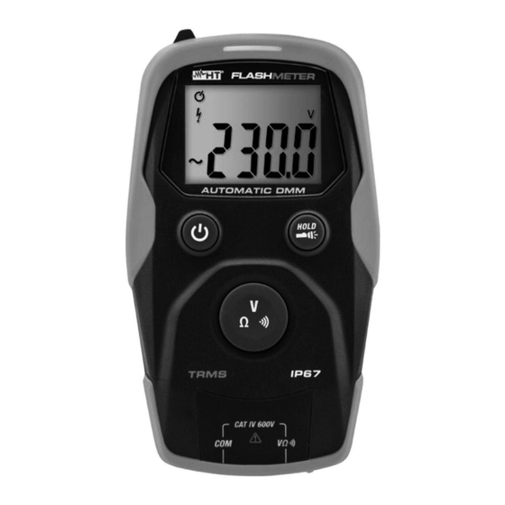
- Page 9 FLASHMETER 4. NOMENCLATURA 4.1. DESCRIZIONE DELLO STRUMENTO LEGENDA: 1. Torcia a luce bianca 2. Sensore NCV 3. Visualizzatore presenza tensione AC senza contatto 4. Display LCD 5. Tasto ON/OFF 6. Tasto HOLD/ 7. Tasto V/Ω/ 8. Terminale di ingresso COM 9.
- Page 10 FLASHMETER 4.3. DESCRIZIONE DEI TASTI FUNZIONE 4.3.1. Tasto ON/OFF ( ) consente l’accensione dello strumento. Premere per circa 1s il La pressione del tasto tasto per spegnere lo strumento. 4.3.2. Tasto HOLD/ permette l’attivazione/disattivazione della torcia a luce La pressione del tasto HOLD/ bianca integrata (vedere Fig.
- Page 11 FLASHMETER 5. ISTRUZIONI OPERATIVE 5.1. MISURA TENSIONE DC ATTENZIONE La massima tensione DC in ingresso è 600V. Non misurare tensioni che eccedono i limiti indicati in questo manuale. Il superamento dei limiti di tensione potrebbe causare shock elettrici all’utilizzatore e danni allo strumento.
- Page 12 FLASHMETER 5.2. MISURA TENSIONE AC ATTENZIONE • La massima tensione AC in ingresso è 600V. Non misurare tensioni che eccedono i limiti indicati in questo manuale. Il superamento dei limiti di tensione potrebbe causare shock elettrici all’utilizzatore e danni allo strumento •...
- Page 13 FLASHMETER 5.3. MISURA RESISTENZA ATTENZIONE Prima di effettuare qualunque misura di resistenza accertarsi che il circuito in esame non sia alimentato e che eventuali condensatori presenti siano scarichi. Fig. 5: Uso dello strumento per misura di Resistenza 1. Accendere lo strumento premendo il tasto ON/OFF. Il modo di misura Ω è...
- Page 14 FLASHMETER 5.4. TEST CONTINUITÀ ATTENZIONE Prima di effettuare qualunque misura di resistenza accertarsi che il circuito in esame non sia alimentato e che eventuali condensatori presenti siano scarichi. Fig. 6: Uso dello strumento per il Test Continuità 1. Accendere lo strumento premendo il tasto ON/OFF. Il modo di misura Ω è...
- Page 15 FLASHMETER 6. MANUTENZIONE 6.1. GENERALITÀ • Lo strumento da Lei acquistato è uno strumento di precisione. Durante l’uso e la conservazione rispettare le raccomandazioni elencate in questo manuale per evitare possibili danni o pericoli durante l’utilizzo • Non utilizzare lo strumento in ambienti caratterizzati da elevato tasso di umidità o temperatura elevata.
- Page 16 FLASHMETER 7. SPECIFICHE TECNICHE 7.1. CARATTERISTICHE TECNICHE Incertezza calcolata come ±[%lettura + (num. cifre*risoluz.)] riferita a 18°C28°C,<70%RH Tensione DC (Autorange) Impedenza di Protezione contro Campo Risoluzione Incertezza ingresso i sovraccarichi 400.0V (1.0%lettura+5cifre) >10MΩ 0.1V 600VDC/ACrms 600.0V Tensione AC TRMS (Autorange)
- Page 17 FLASHMETER Display Caratteristiche: LCD 4 cifre, 4000 punti, segno e punto decimale con backlight simbolo “OL.” a display Indicazione fuori scala: Frequenza campionamento: 3volte/s Conversione: TRMS 7.3. AMBIENTE 7.3.1. Condizioni ambientali di utilizzo 18°C 28°C Temperatura di riferimento: Temperatura di utilizzo: 0°C ÷...
- Page 18 FLASHMETER 8. ASSISTENZA 8.1. CONDIZIONI DI GARANZIA Questo strumento è garantito contro ogni difetto di materiale e fabbricazione, in conformità con le condizioni generali di vendita. Durante il periodo di garanzia, le parti difettose possono essere sostituite, ma il costruttore si riserva il diritto di riparare ovvero sostituire il prodotto.
- Page 19 ENGLISH User manual © Copyright HT ITALIA 2024 Release EN 4.01 - 05/12/2024...
- Page 20 FLASHMETER TABLE OF CONTENTS PRECAUTIONS AND SAFETY MEASURES ............... 2 1.1. Preliminary instructions ..................... 2 1.2. During use ......................... 3 1.3. After use ..........................3 1.4. Definition of Measurement (Overvoltage) category ............3 GENERAL DESCRIPTION ................... 4 2.1. Measuring average values andTRMS values ..............4 2.2.
- Page 21 FLASHMETER 1. PRECAUTIONS AND SAFETY MEASURES The instrument has been designed in compliance with directive IEC/EN61010-1 relevant to electronic measuring instruments. For your safety and in order to prevent damaging the instrument, please carefully follow the procedures described in this manual and read all notes preceded by symbol with the utmost attention.
- Page 22 FLASHMETER 1.2. DURING USE Please carefully read the following recommendations and instructions: CAUTION Failure to comply with the caution notes and/or instructions may damage the instrument and/or its components or be a source of danger for the operator. • When the instrument is connected to the circuit being measured, do not touch any unused terminal.
- Page 23 FLASHMETER 2. GENERAL DESCRIPTION The instrument carries out the following measurements in full Autorange: • DC Voltage • AC TRMS Voltage • Detection of AC Voltage without contact • Resistance and Continuity test According to the quantity present at the input, the instrument automatically switches between voltage and resistance measurement.
- Page 24 FLASHMETER 3. PREPARATION FOR USE 3.1. INITIAL CHECKS Before shipping, the instrument has been checked from an electric as well as mechanical point of view. All possible precautions have been taken so that the instrument is delivered undamaged. However, we recommend generally checking the instrument in order to detect possible damage suffered during transport.
- Page 25 FLASHMETER 4. NOMENCLATURE 4.1. DESCRIPTION OF THE INSTRUMENT CAPTION: 1. White-light torch 2. NCV sensor 3. Detector of AC voltage without contact 4. LCD display 5. ON/OFF key 6. HOLD/ 7. V/Ω/ key 8. Input terminal COM 9. Input terminal V/Ω/ Fig.
- Page 26 FLASHMETER 4.3. DESCRIPTION OF FUNCTION KEYS 4.3.1. ON/OFF key ( ) Pressing the key allows turning on the instrument. Press and hold the key for approx. 1s to turn off the instrument. 4.3.2. HOLD/ Pressing the HOLD/ key allows activating/deactivating the built-in white-light torch (see –...
- Page 27 FLASHMETER 5. OPERATING INSTRUCTIONS 5.1. DC VOLTAGE MEASUREMENT CAUTION The maximum input DC voltage is 600V. Do not measure voltages exceeding the limits given in this manual. Exceeding voltage limits could result in electrical shocks to the user and damage to the instrument.
- Page 28 FLASHMETER 5.2. AC VOLTAGE MEASUREMENT CAUTION • The maximum input AC voltage is 600V. Do not measure voltages exceeding the limits given in this manual. Exceeding voltage limits could result in electrical shocks to the user and damage to the instrument •...
- Page 29 FLASHMETER 5.3. RESISTANCE MEASUREMENT CAUTION Before attempting any resistance measurement, cut off power supply from the circuit to be measured and make sure that all capacitors are discharged, if present. Fig. 5: Use of the instrument for Resistance measurement Ω...
- Page 30 FLASHMETER 5.4. CONTINUITY TEST CAUTION Before attempting any resistance measurement, cut off power supply from the circuit to be measured and make sure that all capacitors are discharged, if present. Fig. 6: Use of the instrument for Continuity test Ω...
- Page 31 FLASHMETER 6. MAINTENANCE 6.1. GENERAL INFORMATION • The instrument you purchased is a precision instrument. While using and storing the instrument, carefully observe the recommendations listed in this manual in order to prevent possible damage or danger during use. • Do not use the instrument in environments with high humidity levels or high temperatures.
- Page 32 FLASHMETER 7. TECHNICAL SPECIFICATIONS 7.1. TECHNICAL CHARACTERISTICS Accuracy calculated as ±[%reading + (num. digits*resol)] referred to 18°C28°C,<70%RH DC voltage (Autorange) Protection against Range Resolution Accuracy Input impedance overcharge 400.0V (1.0%rdg+5digits) Ω 0.1V >10M 600VDC/ACrms 600.0V AC TRMS voltage (Autorange) Accuracy (*)
- Page 33 FLASHMETER Display Characteristics: 4-digit LCD, 4000 dots, decimal sign and point with backlight “ ” Out-of-range indication: symbol on the display Sampling frequency: 3times/s Conversion: TRMS 7.3. ENVIRONMENT 7.3.1. Environmental conditions for use 18°C 28°C (64°F 82°F) Reference temperature: 0°C ÷...
- Page 34 FLASHMETER 8. ASSISTANCE 8.1. WARRANTY CONDITIONS This instrument is warranted against any material or manufacturing defect, in compliance with the general sales conditions. During the warranty period, defective parts may be replaced. However, the manufacturer reserves the right to repair or replace the product.
- Page 35 ESPAÑOL Manual de instrucciones © Copyright HT ITALIA 2024 Versión ES 4.01 - 05/12/2024...
- Page 36 FLASHMETER ÍNDICE PRECAUCIONES Y MEDIDAS DE SEGURIDAD ............2 1.1. Instrucciones preliminares ....................2 1.2. Durante la utilización ......................3 1.3. Después de la utilización ....................3 1.4. Definición de Categoría de medida (Sobretensión) ............3 DESCRIPCIÓN GENERAL ................... 4 2.1.
- Page 37 FLASHMETER 1. PRECAUCIONES Y MEDIDAS DE SEGURIDAD El instrumento ha sido diseñado en conformidad con las directivas IEC/EN61010-1, relativas a los instrumentos de medida electrónicos. Para su seguridad y para evitar daños en el instrumento, le rogamos que siga los procedimientos descritos en el presente manual y que lea con particular atención todas las notas precedidas por el símbolo...
- Page 38 FLASHMETER 1.2. DURANTE LA UTILIZACIÓN Le rogamos que lea atentamente las recomendaciones y las instrucciones siguientes: ATENCIÓN La falta de observación de las Advertencias y/o Instrucciones puede dañar el instrumento y/o sus componentes o ser fuente de peligro para el operador.
- Page 39 FLASHMETER 2. DESCRIPCIÓN GENERAL El instrumento realiza en total Autorango, las siguientes medidas: • Tensión CC • Tensión CA TRMS • Detección presencia de tensión CA sin contacto • Resistencia y prueba de continuidad El instrumento, en base a la magnitud presente en la entrada, conmuta automáticamente entre las medidas de tensión y resistencia.
- Page 40 FLASHMETER 3. PREPARACIÓN A LA UTILIZACIÓN 3.1. CONTROLES INICIALES El instrumento, antes de ser suministrado, ha sido controlado desde el punto de vista eléctrico y mecánico. Han sido tomadas todas las precauciones posibles para que el instrumento pueda ser entregado sin daños. Aun así se aconseja, que controle someramente el instrumento para detectar eventuales daños sufridos durante el...
- Page 41 FLASHMETER 4. NOMENCLATURA 4.1. DESCRIPCIÓN DEL INSTRUMENTO LEYENDA: 1. Linterna de luz blanca 2. Sensor NCV 3. Visualizador presencia de tensión CA sin contacto 4. Visualizador LCD 5. Tecla ON/OFF 6. Tecla HOLD/ 7. Tecla V/Ω/ 8. Borne de entrada COM 9.
- Page 42 FLASHMETER 4.3. DESCRIPCIÓN DE LAS TECLAS DE FUNCIÓN 4.3.1. Tecla ON/OFF ( ) La pulsación de la tecla permite el encendido del instrumento. Pulse durante aproximadamente 1s la tecla para apagar el instrumento. 4.3.2. Tecla HOLD/ La pulsación de la tecla AutoHold/ permite la activación/desactivación de la linterna...
- Page 43 FLASHMETER 5. INSTRUCCIONES OPERATIVAS 5.1. MEDIDA DE TENSIÓN CC ATENCIÓN La tensión máxima CC en la entrada es de 600V. No mida tensiones que excedan los límites indicados en este manual. La superación de los límites de tensión podría causar shocks eléctricos al usuario y daños al instrumento.
- Page 44 FLASHMETER 5.2. MEDIDA DE TENSIÓN CA ATENCIÓN • La tensión máxima CA en la entrada es de 600V. No mida tensiones que excedan los límites indicados en este manual. La superación de los límites de tensión podría causar shocks eléctricos al usuario y daños al instrumento •...
- Page 45 FLASHMETER 5.3. MEDIDA DE RESISTENCIA ATENCIÓN Antes de efectuar cualquier medida de resistencia asegúrese que el circuito en examen no esté alimentado y que eventuales condensadores presentes estén descargados. Fig. 5: Uso del instrumento para medida de Resistencia 1. Encienda el instrumento pulsando la tecla ON/OFF. El modo de medida Ω se selecciona automáticamente y la indicación “OL.”...
- Page 46 FLASHMETER 5.4. PRUEBA DE CONTINUIDAD ATENCIÓN Antes de efectuar cualquier medida de resistencia asegúrese que el circuito en examen no esté alimentado y que eventuales condensadores presentes estén descargados. Fig. 6: Uso del instrumento para la prueba de continuidad 1. Encienda el instrumento pulsando la tecla ON/OFF. El modo de medida Ω se selecciona automáticamente y la indicación “OL.”...
- Page 47 FLASHMETER 6. MANTENIMIENTO 6.1. GENERALIDADES • El instrumento adquirido por usted es un instrumento de precisión. Durante la utilización y el almacenamiento respete las recomendaciones listadas en este manual para evitar posibles daños o peligros durante la utilización. • No utilice el instrumento en ambientes caracterizados por una elevada tasa de humedad o temperatura elevada.
- Page 48 FLASHMETER 7. ESPECIFICACIONES TÉCNICAS 7.1. CARACTERÍSTICAS TÉCNICAS Incertidumbre calculada como ±[%lectura + (núm.dgt*resol.)] a 18°C28°C,<70%RH Tensión CC (Autorango) Impedancia de Protección contra Rango Resolución Incertidumbre entrada sobrecargas 400.0V (1.0%lectura+5díg.) >10MΩ 0.1V 600VCC/CArms 600.0V Tensión CA TRMS (Autorango) Incertidumbre (*) Impedancia de Protección contra...
- Page 49 FLASHMETER Visualizador Características: LCD 4 dígitos, 4000 puntos, signo y punto decimal con retroiluminación símbolo “OL.” en pantalla Indicación fuera de rango: Frecuencia de muestreo: 3 veces Conversión: TRMS 7.3. AMBIENTE 7.3.1. Condiciones ambientales de utilización 18°C 28°C Temperatura de referencia: Temperatura de utilización:...
- Page 50 FLASHMETER 8. ASISTENCIA 8.1. CONDICIONES DE GARANTÍA Este instrumento está garantizado contra cada defecto de materiales y fabricaciones, conforme con las condiciones generales de venta. Durante el período de garantía, las partes defectuosas pueden ser sustituidas, pero el fabricante se reserva el derecho de repararlo o bien sustituir el producto.
- Page 51 DEUTSCH Bedienungsanleitung © Copyright HT ITALIA 2024 Ausführung DE 4.01 - 05/12/2024...
- Page 52 FLASHMETER INHALT SICHERHEITSVORKEHRUNGEN UND -VERFAHREN ..........2 1.1. Vorwort ..........................2 1.2. Während des Gebrauchs ....................3 1.3. Nach dem Gebrauch ......................3 1.4. Messkategorien-Definition (Überspannungskategorien) ........... 3 ALLGEMEINE BESCHREIBUNG ................. 5 2.1. Messgeräte mit Mittelwert und mit True RMS ..............5 2.2.
- Page 53 FLASHMETER 1. SICHERHEITSVORKEHRUNGEN UND -VERFAHREN Dieses Gerät entspricht Sicherheitsnorm IEC/EN61010-1 für elektronische Messgeräte. Zu Ihrer eigenen Sicherheit und der des Gerätes müssen Sie den Verfahren folgen, die in dieser Bedienungsanleitung beschrieben werden, und müssen besonders alle Notizen lesen, denen folgendes Symbol voran gestellt ist.
- Page 54 FLASHMETER zeigen. 1.2. WÄHREND DES GEBRAUCHS Wir empfehlen Ihnen, die folgenden Empfehlungen und Anweisungen sorgfältig durchzulesen: ACHTUNG Das Nichtbefolgen der Warnungen und/oder der Gebrauchsanweisungen kann das Gerät und/oder seine Bestandteile beschädigen und eine Gefahr für den Benutzer darstellen. • Berühren Sie nie einen unbenutzten Anschluss, wenn das Messgerät mit dem Schaltkreis verbunden ist.
- Page 55 FLASHMETER Grund erfordert die Norm, dass die Transientenfestigkeit des Gerätes dem Benutzer bekannt sein muss. DE - 4...
- Page 56 FLASHMETER 2. ALLGEMEINE BESCHREIBUNG Gerät führt folgenden Messungen automatischer Funktions- & Messbereichswahl durch: • DC Spannung • AC TRMS Spannung • Ermittlung von Wechselspannung ohne Kontakt • Widerstand- und Durchgangsprüfung Je nach der vorhandenen Eingangsgröße, schaltet das Gerät automatisch zwischen Spannungs- und Widerstandsmessung.
- Page 57 FLASHMETER 3. VORBEREITUNG ZUM GEBRAUCH 3.1. VORBEREITENDE PRÜFUNG Vor dem Versand wurden Elektronik und Mechanik des Messgeräts sorgfältig überprüft.. Zur Auslieferung des Gerätes in optimalem Zustand wurden die bestmöglichen Vorkehrungen getroffen. Dennoch ist es ratsam, einen Check durchzuführen, um einen möglichen Schaden zu entdecken, der während des Transports verursacht worden sein...
- Page 58 FLASHMETER 4. NOMENKLATUR 4.1. BESCHREIBUNG DES GERÄTS LEGENDE: 1. Lampe mit weißem Licht 2. NCV-Sensor 3. Signalleuchte für Wechselspannung ohne Kontakt 4. LCD-Anzeige 5. Taste ON/OFF 6. Taste HOLD/ 7. Taste V/Ω/ 8. Eingangsbuchse COM 9. Eingangsbuchse V/Ω/ Abb. 1: Beschreibung des Geräts 4.2.
- Page 59 FLASHMETER 4.3. BESCHREIBUNG DER FUNKTIONSTASTEN 4.3.1. Taste ON/OFF ( ) Drücken sie die Taste , um das Gerät einzuschalten. Drücken und halten Sie die Taste für ca. 1 Sekunde, um das Gerät auszuschalten. 4.3.2. Taste HOLD/ Drücken sie die HOLD/ Taste, um die eingebaute Lampe mit weißem Licht zu...
- Page 60 FLASHMETER 5. ANWEISUNGEN ZUM GEBRAUCH 5.1. DC SPANNUNGSMESSUNG WARNUNG Die maximale DC Eingangsspannung beträgt 600V. Versuchen Sie nicht, Spannungen zu messen, die die Grenzwerte, die in diesem Handbuch angegebenen werden, überschreiten. Das Überschreiten der Spannungs- Grenzwerte könnte einen elektrischen Schock verursachen und das Messgerät beschädigen.
- Page 61 FLASHMETER 5.2. AC SPANNUNGSMESSUNG WARNUNG • Die maximale AC-Eingangsspannung beträgt 600V. Versuchen Sie nicht, Spannungen zu messen, die die Grenzwerte, die in diesem Handbuch angegebenen werden, überschreiten. Das Überschreiten der Spannungs- Grenzwerte könnte einen elektrischen Schock verursachen und das Messgerät beschädigen •...
- Page 62 FLASHMETER 5.3. WIDERSTANDSMESSUNG WARNUNG Entfernen Sie vor jeder Widerstandsmessung alle Spannungen vom Messobjekt und entladen Sie alle Kondensatoren, falls vorhanden. Abb. 5: Verwendung des Gerätes für Widerstandsmessung Ω 1. Schalten Sie das Gerät mit der ON/OFF Taste ein. Der Messmodus wird automatisch “...
- Page 63 FLASHMETER 5.4. DURCHGANGSPRÜFUNG WARNUNG Entfernen Sie vor jeder Widerstandsmessung alle Spannungen vom Messobjekt und entladen Sie alle Kondensatoren, falls vorhanden. Abb. 6: Verwendung des Gerätes für Durchgangstest Ω 1. Schalten Sie das Gerät mit der ON/OFF Taste ein. Der Messmodus wird automatisch “...
- Page 64 FLASHMETER 6. WARTUNG UND PFLEGE 6.1. ALLGEMEINE INFORMATIONEN • Das Gerät, das Sie gekauft haben, ist ein Präzisionsinstrument. Überschreiten Sie niemals die technischen Grenzwerte in dieser Bedienungsanleitung bei der Messung oder bei der Lagerung, um mögliche Beschädigungen oder Gefahren zu vermeiden.
- Page 65 FLASHMETER 7. TECHNISCHE DATEN 7.1. TECHNISCHE EIGENSCHAFTEN Die Messgenauigkeit ist angegeben als ±[%Ablesung + (Ziffern*Auflösung)] bei 18°C28°C,<70%RH. DC Spannung (Autorange) Eingangs- Bereich Auflösung Genauigkeit Überlastschutz widerstand 400.0V (1.0%Abl+5Ziff) Ω 0.1V >10M 600VDC/ACrms 600.0V AC TRMS Spannung (Autorange) Genauigkeit (*) Eingangs- Bereich Auflösung...
- Page 66 FLASHMETER Display Eigenschaften: LCD, 4 Ziffern, 4000 Punkte, Dezimalzeichen und -punkt, Hintergrundbeleuchtung “ ” Überlastanzeige: Symbol im Display Abtastfrequenz: 3mal/s Konversion: TRMS 7.3. UMWELTBEDINGUNGEN 7.3.1. Klimabedingungen für den Gebrauch 18°C 28°C Bezugstemperatur: Betriebstemperatur: 0°C ÷ 50°C Zulässige relative Luftfeuchtigkeit: <75%RH...
- Page 67 FLASHMETER 8. SERVICE 8.1. GARANTIEBEDINGUNGEN Für dieses Gerät gewähren wir Garantie auf Material- oder Produktionsfehler, entsprechend unseren allgemeinen Geschäftsbedingungen. Während der Garantiefrist behält sich der Hersteller das Recht vor, das Produkt wahlweise zu reparieren oder zu ersetzen. Falls Sie das Gerät aus irgendeinem Grund für Reparatur oder Austausch einschicken müssen, setzen Sie sich bitte zuerst mit dem lokalen Händler in Verbindung,...
- Page 68 FRANÇAIS Manuel d'utilisation © Copyright HT ITALIA 2024 Version FR 4.01 - 05/12/2024...
- Page 69 FLASHMETER TABLE DES MATIERES PRECAUTIONS ET MESURES DE SECURITE ............2 1.1. Instructions préliminaires ....................2 ’ 1.2. Durant l utilisation ......................3 ’ 1.3. Après l utilisation ....................... 3 1.4. Définition de Catégorie de mesure (Surtension) ............... 3 DESCRIPTION GENERALE ..................4 2.1.
- Page 70 FLASHMETER 1. PRECAUTIONS ET MESURES DE SECURITE Cet instrument a été conçu conformément à la directive IEC/EN61010-1, relative aux ’ instruments de mesure électroniques. Pour votre propre sécurité et afin d éviter tout ’ endommagement de l instrument, veuillez suivre avec précaution les instructions décrites dans ce manuel et lire attentivement toutes les remarques précédées du symbole...
- Page 71 FLASHMETER ’ 1.2. DURANT L UTILISATION Veuillez lire attentivement les recommandations et instructions suivantes: ATTENTION Le non-respect des avertissements et/ou instructions peut endommager ’ ’ instrument et/ou ses composants et mettre en danger l utilisateur. • Lorsque l ’ instrument est connecté au circuit sous test, ne jamais toucher les bornes inutilisées...
- Page 72 FLASHMETER 2. DESCRIPTION GENERALE L'instrument exécute, en Autorange total, les mesures suivantes : • Tension DC • Tension AC TRMS • Détection de la présence de tension AC sans contact • Résistance et test de continuité L'instrument, en fonction de la grandeur présente en entrée, commute automatiquement entre les mesures de tension et résistance.
- Page 73 FLASHMETER 3. PREPARATION A L'UTILISATION 3.1. VERIFICATION INITIALE ’ ’ ’ ’ instrument a fait l objet d un contrôle mécanique et électrique avant d être expédié. ’ Toutes les précautions possibles ont été prises pour garantir une livraison de l instrument ’...
- Page 74 FLASHMETER 4. NOMENCLATURE ’ 4.1. DESCRIPTION DE L INSTRUMENT LEGENDE : 1. Torche à lumière blanche 2. Capteur NCV 3. Affiche la présence de tension CA sans contact 4. Écran LCD 5. Touche ON/OFF 6. Touche HOLD/ 7. Touche V// 8.
- Page 75 FLASHMETER 4.3. DESCRIPTION DES TOUCHES DE FONCTION 4.3.1. Touche ON/OFF ( ) La pression de la touche permet l'allumage de l'instrument. Appuyer environ 1s sur la touche pour éteindre l'instrument. 4.3.2. Touche HOLD/ La pression de la touche HOLD/ permet l'activation/désactivation de la torche à...
- Page 76 FLASHMETER 5. MODE D'EMPLOI 5.1. MESURE DE TENSION CC ATTENTION ’ La tension d entrée maximale CC est de 600V. Ne pas mesurer de tensions excédant les limites indiquées dans ce manuel. Le dépassement des limites de tension pourrait entraîner des chocs électriques pour l'utilisateur et ’...
- Page 77 FLASHMETER 5.2. MESURE DE TENSION CA ATTENTION • La tension d ’ entrée maximale Ca est de 600V. Ne pas mesurer de tensions excédant les limites indiquées dans ce manuel. Le dépassement des limites de tension pourrait entraîner des chocs électriques pour l'utilisateur et endommager l ’...
- Page 78 FLASHMETER 5.3. MESURE DE RESISTANCE ATTENTION ’ Avant d'effectuer toute mesure de résistance, vérifier que l alimentation du circuit sous test est coupée et que tous les condensateurs, si présents, sont déchargés. Fig. 5: Mesure de Résistance instrument en appuyant sur la touche ON/OFF Le mode de mesure Ω est ’...
- Page 79 FLASHMETER 5.4. TEST DE CONTINUITE ATTENTION ’ Avant d'effectuer toute mesure de résistance, vérifier que l alimentation du circuit sous test est coupée et que tous les condensateurs, si présents, sont déchargés. Fig. 6: Utilisation de l'instrument pour le test de continuité...
- Page 80 FLASHMETER 6. MAINTENANCE 6.1. ASPECTS GENERAUX • L ’ instrument que vous avez acheté est un instrument de précision. Pour son usage et son stockage, veuillez suivre attentivement les recommandations indiquées dans ce manuel afin d ’ éviter tout dommage ou danger pendant l ’...
- Page 81 FLASHMETER 7. SPECIFICATIONS TECHNIQUES 7.1. CARACTERISTIQUES TECHNIQUES Incertitude calculée comme ±[%lecture + (num.dgts*résolution)] à 18°C28°C,<70%RH Tension DC (Autorange) Protection contre ’ Champ Résolution Incertitude Impédance d entrée les surcharges 400.0V (1.0%lecture+5dgts) Ω 0.1V >10M 600VDC/ACrms 600.0V Tension AC TRMS (Autorange)
- Page 82 FLASHMETER Écran Caractéristiques : LCD 4 chiffres, 4000 points, signe et point décimal avec rétro éclairage “ ” Indicatin hors échelle : symbole à l'écran ’ Taux d échantillonnage: 3 fois/s Conversion : TRMS 7.3. ENVIRONNEMENT 7.3.1. Conditions environnementales d'utilisation 18°C ...
- Page 83 FLASHMETER 8. ASSISTANCE 8.1. CONDITIONS DE GARANTIE Cet instrument est garanti contre tout défaut de matériel ou de fabrication, conformément aux conditions générales de vente. Pendant la période de garantie, toutes les pièces défectueuses peuvent être remplacées, mais le fabricant se réserve le droit de réparer ou ’...
- Page 84 PORTUGUÊS Manual de instruções © Copyright HT ITALIA 2024 Versão PT 4.01 - 05/12/2024...
- Page 85 FLASHMETER ÍNDICE PRECAUÇÕES E MEDIDAS DE SEGURANÇA ............2 1.1. Instruções preliminares ..................... 2 1.2. Durante a utilização ......................3 1.3. Após a utilização ....................... 3 1.4. Definição de Categoria de medida (Sobretensão) ............3 DESCRIÇÃO GERAL ....................4 2.1.
- Page 86 FLASHMETER 1. PRECAUÇÕES E MEDIDAS DE SEGURANÇA Este instrumento foi construído em conformidade com a norma EN 61010-1 referente aos instrumentos de medida eletrónicos. Para Sua segurança e para evitar danificar o instrumento, deve seguir os procedimentos descritos neste manual e ler com especial atenção todas as notas precedidas do símbolo...
- Page 87 FLASHMETER 1.2. DURANTE A UTILIZAÇÃO Ler atentamente as recomendações e as instruções seguintes: ATENÇÂO O não cumprimento das Advertências e/ou Instruções podem danificar o instrumento e/ou os seus componentes ou colocar em perigo o operador. • Quando o instrumento está ligado ao circuito em exame nunca tocar num terminal inutilizado.
- Page 88 FLASHMETER 2. DESCRIÇÃO GERAL O instrumento executa em Escala Automática total, as seguintes medições: • Tensão CC • Tensão CA TRMS • Deteção da presença de tensão CA sem contacto • Resistência e teste de continuidade O instrumento, em função da grandeza presente na entrada, comuta automaticamente entre as medições de tensão e resistência.
- Page 89 FLASHMETER 3. PREPARAÇÃO PARA A SUA UTILIZAÇÃO 3.1. CONTROLOS INICIAIS O instrumento, antes de ser expedido, foi controlado do ponto de vista elétrico e mecânico. Foram tomadas todas as precauções possíveis para que o instrumento seja entregue sem danos. Todavia, aconselha-se a efetuar uma verificação geral ao instrumento para se certificar de possíveis danos ocorridos durante o transporte.
- Page 90 FLASHMETER 4. NOMENCLATURA 4.1. DESCRIÇÃO DO INSTRUMENTO LEGENDA: 1. Lanterna com luz branca 2. Sensor NCV 3. Visualizador da presença de tensão AC sem contacto 4. Display LCD 5. Botão ON/OFF 6. Botão HOLD/ 7. Botão V/Ω/ 8. Terminal de entrada COM 9.
- Page 91 FLASHMETER 4.3. DESCRIÇÃO DOS BOTÕES DE FUNÇÕES 4.3.1. Botão ON/OFF ( ) A pressão do botão permite ligar o instrumento. Premir durante cerca de 1s o botão para desligar o instrumento. 4.3.2. Botão HOLD/ A pressão do botão HOLD/ permite a ativação/desativação da lanterna com luz branca integrada (ver Fig.
- Page 92 FLASHMETER 5. INSTRUÇÕES DE FUNCIONAMENTO 5.1. MEDIÇÃO DE TENSÃO CC ATTENZIONE A tensão CC máxima na entrada é 600V. Não medir tensões que excedam os limites expressos neste manual. A passagem destes limites poderá provocar choques elétricos no utilizador e danos no instrumento.
- Page 93 FLASHMETER 5.2. MEDIÇÃO DE TENSÃO CA ATTENZIONE • A tensão CA máxima na entrada é 600V. Não medir tensões que excedam os limites expressos neste manual. A passagem destes limites poderá provocar choques elétricos no utilizador e danos no instrumento •...
- Page 94 FLASHMETER 5.3. MEDIÇÃO DE RESISTÊNCIAS ATENÇÃO Antes de efetuar uma medição de resistência, verificar se o circuito em exame não está a ser alimentado e se existirem condensadores, os mesmos estão descarregados. Fig. 5: Uso do instrumento para a medição de Resistências 1.
- Page 95 FLASHMETER 5.4. TESTE DE CONTINUIDADE ATENÇÃO Antes de efetuar uma medição de resistência, verificar se o circuito em exame não está a ser alimentado e se existirem condensadores, os mesmos estão descarregados. Fig. 6: Uso do instrumento para o Teste de Continuidade 1.
- Page 96 FLASHMETER 6. MANUTENÇÃO 6.1. GENERALIDADES • Este aparelho é um instrumento de precisão. Durante a sua utilização e armazenamento, respeitar as recomendações apresentadas neste manual para evitar possíveis danos ou perigos durante a utilização. • Não utilizar o instrumento em ambientes caracterizados por taxas de humidade ou temperatura elevadas.
- Page 97 FLASHMETER 7. ESPECIFICAÇÕES TÉCNICAS 7.1. CARACTERÍSTICAS TÉCNICAS A precisão é calculada como ±[%leitura + (num dgt*resolução)] à 18°C28°C,<70%RH. Tensão CC (Escala Automática) Impedância de Proteção contra Escalas Resolução Precisão entrada sobrecargas 400.0V (1.0%leitura+5dgt) >10MΩ 0.1V 600VDC/ACrms 600.0V Tensão CA TRMS (Escala Automática) Precisão (*)
- Page 98 FLASHMETER Display Características: LCD 4 dígitos, 4000 pontos, sinal e ponto decimal com retroiluminação símbolo “OL.” no display Indicação de fora de escala: Frequência de amostragem: 3vezes/s Conversão: TRMS 7.3. AMBIENTE 7.3.1. Condições ambientais de utilização 18°C 28°C Temperatura de referência: Temperatura de utilização:...
- Page 99 FLASHMETER 8. ASSISTÊNCIA 8.1. CONDIÇÕES DE GARANTIA Este instrumento está garantido contra qualquer defeito de material e fabrico, em conformidade com as condições gerais de venda. Durante o período da garantia, as partes defeituosas podem ser substituídas, mas ao construtor reserva-se o direito de reparar ou substituir o produto.
- Page 101 48018 – Faenza (RA) – Italy WE ARE T +39 0546 621002 | F +39 0546 621144 M info@ht-instrumnents.com | www.ht-instruments.it HT INSTRUMENTS SL C/ Legalitat, 89 08024 Barcelona – Spain T +34 93 408 17 77 | F +34 93 408 36 30 M info@htinstruments.es | www.ht-instruments.com/es-es/...
Need help?
Do you have a question about the FLASHMETER and is the answer not in the manual?
Questions and answers