
Related Manuals for HT Instruments HT9019


Summary of Contents for HT Instruments HT9019
- Page 1 ENGLISH User manual 1.888.610.7664 www.calcert.com sales@calcert.com Copyright HT ITALIA 2013 Release EN 2.00 - 18/04/2013...
-
Page 2: Table Of Contents
HT9019 Table of contents: SAFETY PRECAUTIONS AND PROCEDURES ............2 1.1. Preliminary ........................2 1.2. During use ......................... 3 1.3. After use ..........................3 1.4. Measuring (overvoltage) categories definitions ..............3 GENERAL DESCRIPTION ................... 4 2.1. ... -
Page 3: Safety Precautions And Procedures
HT9019 1. SAFETY PRECAUTIONS AND PROCEDURES This clamp complies with IEC/EN61010-1. For your own safety and in order to avoid damaging the instrument, you’re recommended to keep to the instructions contained in this manual and read carefully all the notes preceded by the symbol Take extreme care for the following conditions while measuring: ... -
Page 4: During Use
HT9019 1.2. DURING USE Always keep to the instructions contained in this manual. CAUTION Non compliance with the CAUTIONs and/or the instructions may damage the tester and/or its components or injure the operator. Before changing the switch position, take off the clamp jaw from the tested conductor or the electrical circuit in order to avoid any accident ... -
Page 5: General Description
HT9019 2. GENERAL DESCRIPTION HT9019 meter can perform the herewith measurements: DC and AC TRMS Voltage up to 1000V AC TRMS Current up to 1000A Resistance and continuity test with buzzer AC voltage detection with and without contact with integrated sensor Each parameter can be selected by rotating the 7 positions switch. -
Page 6: Preparation For Use
HT9019 3. PREPARATION FOR USE 3.1. INITIAL The tester has been checked from a mechanical and electrical point of view before shipment. Every care has been taken to make sure that the instrument reaches you in perfect conditions. However, it’s advisable to make a rapid check in order to detect any damage which may have occurred in transit. -
Page 7: Operating Instructions
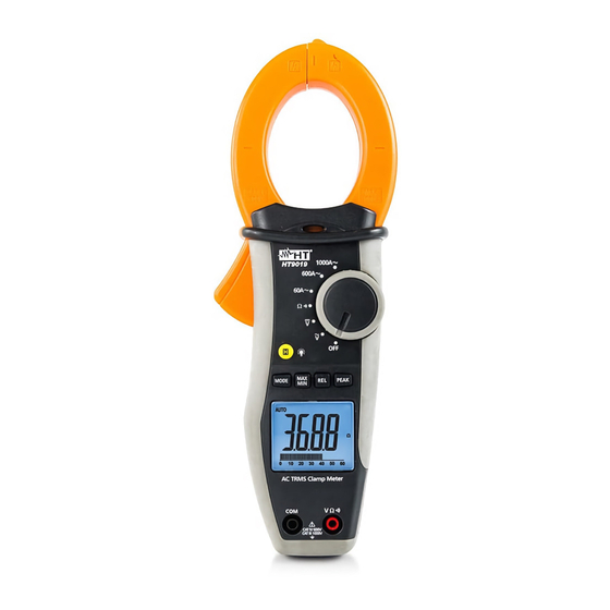
HT9019 4. OPERATING INSTRUCTIONS 4.1. INSTRUMENT DESCRIPTION 4.1.1. Command description CAPTION: 1. Inductive clamp jaw 2. LED for AC voltage detection 3. Jaw trigger 4. Function selector 5. HOLD / 6. MODE, MAX/MIN, Hz%, REL, PEAK function keys 7. LCD display 8. -
Page 8: Function Key Description
HT9019 4.2. FUNCTION KEY DESCRIPTION 4.2.1. H key By pushing “H” key the parameter measured value is frozen on the display and the symbol ”HOLD” appears on it. This mode is disabled by pushing “H” key or moving the rotary switch. -
Page 9: Functions Of Rotary Switch Description
HT9019 4.3. FUNCTIONS OF ROTARY SWITCH DESCRIPTION 4.3.1. AC Voltage measurement CAUTION Maximum input for AC Voltage measurements is 1000Vrms. Do not take any voltage measurement exceeding this limit in order not to risk electrical shock or damaging the tester Fig. -
Page 10: Dc Voltage Measurement
HT9019 4.3.2. DC Voltage measurement CAUTION Maximum input for DC Voltage measurements is 1000V. Do not take any voltage measurement exceeding this limit in order not to risk electrical shock or damaging the tester. Fig. 4: Taking DC voltage measurements 1. -
Page 11: Resistance Measurement And Continuity Test
HT9019 4.3.3. Resistance measurement and Continuity test CAUTION Before taking any in circuit resistance measurement, remove power from the circuit to be tested and discharge all the capacitors. Fig. 5: Taking Resistance measurement and Continuity test 1. Rotate the switch on ... -
Page 12: Ac Current Measurement
HT9019 4.3.4. AC Current measurement CAUTION Make sure that all the test leads are disconnected from the meter terminals for current measurement. Fig. 6: Taking AC current measurements 1. Rotate the switch on 60A, 600A, or 1000A position 2. Put the conductor to be tested inside to the center of clamp jaw to perform accurated measurements. -
Page 13: Maintenance
HT9019 5. MAINTENANCE 5.1. GENERAL INFORMATIONS 1. This digital clamp meter is a precision instrument. Whether in use or in storage, please do not exceed the specification requirements to avoid possible damages or dangers. 2. Do not place this meter at high temperatures or humidity or expose it to direct sunlight. -
Page 14: Technical Specifications
HT9019 6. TECHNICAL SPECIFICATIONS 6.1. CHARACTERISTICS Uncertainty is calculated as [% rdg + (number of dgt) x resolution]. It is referred to the following reference conditions: 18°C 28°C (65°F 83°F) with RH < 75% DC Voltage (Autorange) Overload... -
Page 15: Safety
HT9019 6.1.1. Safety Comply with: IEC/EN61010-1 Insulation: double insulation Pollution degree: Max height of use: 2000m (6562 ft) Installation category: CAT IV 600V, CAT III 1000V to ground, 6.1.2. General data Mechanical characteristics Dimensions (L x W x H): 252 x 88 x 44mm ; 10 x 3 x 2 in... -
Page 16: Service
HT9019 7. SERVICE 7.1. WARRANTY CONDITIONS This equipment is guaranteed against material faults or production defects, in accordance with the general sales conditions. During the warranty period (one year), faulty parts may be replaced. The manufacturer reserves the right to decide either to repair or replace the product.
Need help?
Do you have a question about the HT9019 and is the answer not in the manual?
Questions and answers