Campbell 05103 Product Manual
Wind monitor
Hide thumbs
Also See for 05103:
- User manual (43 pages) ,
- Instruction manual (30 pages) ,
- Product manual (30 pages)

Related Manuals for Campbell 05103


Summary of Contents for Campbell 05103
- Page 1 PRODUCT MANUAL Wind Monitor Series 05103, 05108, 05108-45, and 05305 Revision: 06/2023 2023 Copyright © Campbell Scientific CSL I.D - 256...
- Page 2 Quotations for repairs can be given on request. It is the policy of Campbell Scientific to protect the health of its employees and provide a safe working environment, in support of this policy a “Declaration of Hazardous Material and Decontamination”...
- Page 3 About this manual Please note that this manual was originally produced by Campbell Scientific Inc. primarily for the North American market. Some spellings, weights and measures may reflect this origin. Some useful conversion factors: Area: 1 in (square inch) = 645 mm Mass: 1 oz.
- Page 4 • Periodically (at least yearly) check electrical ground connections. WHILE EVERY ATTEMPT IS MADE TO EMBODY THE HIGHEST DEGREE OF SAFETY IN ALL CAMPBELL SCIENTIFIC PRODUCTS, THE CUSTOMER ASSUMES ALL RISK FROM ANY INJURY RESULTING FROM IMPROPER INSTALLATION, USE, OR MAINTENANCE OF TRIPODS, TOWERS, OR ATTACHMENTS TO TRIPODS AND TOWERS...
-
Page 5: Table Of Contents
Table of contents 1. Introduction 2. Precautions 3. Initial inspection 4. QuickStart 5. Overview 6. Specifications 7. Installation 7.1 Wiring 7.2 Programming 7.2.1 Wind speed 7.2.2 Wind direction 7.2.3 WindVector processing instruction 7.3 Siting 7.4 Assembly and mounting 8. Sensor maintenance 9. -
Page 6: Introduction
Wire colour and functions of sensors purchased through Campbell Scientific may not correspond with the wire colours and functions given in the manufacturer’s manual. To ensure proper function, follow the wiring provided in Short Cut or in the Campbell Scientific manual. -
Page 7: Initial Inspection
Upon receipt of the wind monitor, inspect the packaging and contents for damage. File damage claims with the shipping company. Immediately check package contents against the shipping documentation. Contact Campbell Scientific about any discrepancies. The model number and cable length are printed on a label at the connection end of the cable. - Page 8 3. In the Available Sensors and Devices box, type 05103, 05106, or 05305 AQ or locate the sensor in the Sensors > Meteorological > Wind Speed & Direction folder. Double-click 05103 Wind Speed & Direction Sensor, 05108 Wind Speed & Direction Sensor, 05108-45 Wind Speed &...
- Page 9 6. In Output Setup, enter the scan rate, Data Output Storage Intervals, and meaningful table names. 7. Select the measurement and its associated output options. 8. Click Finish and save the program. Send the program to the data logger if the data logger is connected to the computer.
-
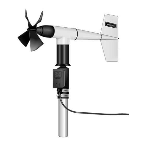
Page 10: Overview
The R. M. Young Instruction Manual includes additional information on the operating principles, installation, and maintenance of the sensor. The wind monitors are manufactured by R. M. Young and cabled by Campbell Scientific for use with our data loggers. Cable lengths for the wind monitors are specified when the sensors are ordered. -
Page 11: Specifications
(p. 7), and Table 6-3 (p. 8) provide the wind speed, wind direction, and physical specifications, respectively. Table 6-1: Wind speed specifications 05108-45 05108 05305 05103 Heavy Duty Heavy Duty Wind Monitor- Wind Monitor Wind Monitor- Wind Monitor Alpine 0 to 50 m/s... - Page 12 Table 6-2: Wind direction specifications 05108-45 05108 05305 05103 Heavy Duty Heavy Duty Wind Monitor- Wind Monitor Wind Monitor- Wind Monitor Alpine Range 0° to 360° mechanical, 355° electrical (5° open) Accuracy ±3° Starting threshold 1.1 m/s (2.4 mph) 1.0 m/s (2.0 mph) 0.5 m/s (1.0 mph)
-
Page 13: Installation
QuickStart (p. 2) for a Short Cut tutorial. 7.1 Wiring Connections to Campbell Scientific data loggers are given in Table 7-1 (p. 9). When Short Cut software is used to create the data logger program, the sensor is wired to the terminals shown in the wiring diagram created by Short Cut. -
Page 14: Programming
Table 7-1: Wire colour, wire function, and data logger connection Wire colour Wire function Data logger connection terminal U configured for pulse input , P (pulse input), WS signal or P_LL (pulse, low-level AC) Black WS signal reference ⏚ U configured for single-ended analogue Green WD signal input... -
Page 15: Wind Direction
(p. 10) lists the multipliers to obtain miles/hour or metres/second when the measurement instruction is configured to output Hz. Table 7-2: Wind speed multiplier Metres/second Miles/hour Model output output 05103 0.2192 0.0980 05108 or 05108-45 0.3726 0.1666 05305 0.2290 0.1024 Set the offset to zero since the helicoid propeller calibration passes through zero (Gill, 1973;... -
Page 16: Windvector Processing Instruction
Table 7-3: Parameters for wind direction CR800, CR300 CR850, CR1000X CR3000 Series CR1000 Measurement range mV2500 mV2500 mV5000 mV5000 mV5000 Excitation voltage 2500 mV 2500 mV 2500 mV 2500 mV 5000 mV Reverse excitation True True True True Delay or settling time 20000 µs 20000 µs 20000 µs... - Page 17 Unthreaded aluminium pipe, 1-inch IPS, 12-inch length (shipped with the sensor) 1-inch-by-1-inch Nu-Rail crossover fitting Wind monitor body Propeller Orientation ring Ferrite choke (shipped with sensor) The following procedure is for assembling the sensor and mounting it to a crossarm. 1.
- Page 18 oriented north-south, east west, or any other angle desired. Wind direction sensor orientation (p. 20) contains detailed information on determining true north by using a compass and the magnetic declination for the site. 5. Secure the 12-inch aluminum pipe to the Nu-Rail fitting. 6.
-
Page 19: Sensor Maintenance
Figure 7-3. CM221 Right-Angle Mounting Kit Figure 7-4. The CM216 allows the wind monitor to mount atop a tripod mast 8. Sensor maintenance Every month do a visual/audio inspection of the anemometer at low wind speeds. Verify that the propeller and wind vane bearing rotate freely. Inspect the sensor for physical damage. Replace the anemometer bearings when they become noisy, or the wind speed threshold increases above an acceptable level. -
Page 20: Troubleshooting
NOTE: Campbell Scientific recommends factory replacement of the bearings and potentiometer. About this manual Refer to the page of this document for the procedure of acquiring a Returned Materials Authorization (RMA). Mechanically-adept users may choose to replace the bearings or potentiometer themselves. Instructions for replacing the bearings and (www.youngusa.com). -
Page 21: Wind Speed
9.2 Wind speed Symptom: No wind speed 1. Check that the sensor is wired to the pulse terminal specified by the pulse count instruction. 2. Disconnect the sensor from the data logger and use an ohmmeter to check the coil. The resistance between the red and black wires should be about 2075 Ω. -
Page 22: Appendix A. Importing Short Cut Code Into Crbasic Editor
Appendix A. Importing Short Cut code into CRBasic Editor Short Cut creates a .DEF file that contains wiring information and a program file that can be imported into CRBasic Editor. By default, these files reside in the C:\campbellsci\SCWin folder. Import Short Cut program file and wiring information into CRBasic Editor: 1. -
Page 23: Appendix B. Example Program
Appendix B. Example program The following program measures the 05103 every 5 s, and stores mean wind speed, unit vector mean direction, and standard deviation of the direction every 60 minutes. Wiring for the example is given in Table B-1 (p. 18). - Page 24 (1,WS_ms,WindDir,FP2,False,0,0,0) FieldNames("WS_ms_S_WVT,WindDir_D1_WVT,WindDir_SD1_WVT") EndTable 'Main Program BeginProg Scan(5,Sec,1,0) 'Default Data Logger Battery Voltage measurement Batt_Volt: Battery(Batt_Volt) '05103 Wind Speed & Direction Sensor measurements WS_ms and WindDir: 'WS_ms PulseCount(WS_ms,1,P1,5,1,0.098,0) 'WindDir BrHalf(WindDir,1,mV5000,1,Vx1,1,2500,True,20000,60,355,0) WindDir>=360 OR WindDir<0 Then WindDir=0 'Call Data Tables and Store Data...
-
Page 25: Appendix C. Wind Direction Sensor Orientation
Appendix C. Wind direction sensor orientation C.1 Determining true north and sensor orientation Orientation of the wind direction sensor is done after the data logger has been programmed, and the location of true north has been determined. True north is usually found by reading a magnetic compass and applying the correction for magnetic declination;... - Page 26 Figure C-1. Magnetic declination for the contiguous United States (2015) Figure C-2. Declination angles east of true north are subtracted from 0 to get true north Wind Monitor Series...
- Page 27 Figure C-3. Declination angles west of true north are added to 0 to get true north Wind Monitor Series...
-
Page 28: Appendix D. Wind Direction Measurement Theory
It is not necessary to understand the concepts in this section for the general operation of the 05103 with a Campbell Scientific data logger. Figure D-1. 05103 potentiometer in a half bridge circuit BRHalf CRBasic instruction outputs a precise excitation voltage (V... - Page 29 Campbell Scientific Regional Offices Australia France Thailand Location: Garbutt, QLD Australia Location: Montrouge, France Location: Bangkok, Thailand Phone: 61.7.4401.7700 Phone: 0033.0.1.56.45.15.20 Phone: 66.2.719.3399 Email: info@campbellsci.com.au Email: info@campbellsci.fr Email: info@campbellsci.asia Website: www.campbellsci.com.au Website: www.campbellsci.fr Website: www.campbellsci.asia Brazil Germany Location: São Paulo, SP Brazil...
Need help?
Do you have a question about the 05103 and is the answer not in the manual?
Questions and answers