Campbell CS650 Instruction Manual
Water content reflectometers
Hide thumbs
Also See for CS650:
- Instruction manual (56 pages) ,
- User manual (56 pages) ,
- Product manual (55 pages)

Related Manuals for Campbell CS650


Summary of Contents for Campbell CS650
- Page 1 CS650 and CS655 Water Content Reflectometers Revision: 4/18 C o p y r i g h t © 2 0 1 1 - 2 0 1 8 C a m p b e l l S c i e n t i f i c ,...
- Page 4 (780) 454-2655. Campbell Scientific (Canada) Corp. is unable to process any returns until we receive this form. If the form is not received within three days of product receipt or is incomplete, the product will be returned to the client at the client’s expense.
- Page 5 Periodically (at least yearly) check electrical ground connections. WHILE EVERY ATTEMPT IS MADE TO EMBODY THE HIGHEST DEGREE OF SAFETY IN ALL CAMPBELL SCIENTIFIC PRODUCTS, THE CLIENT ASSUMES ALL RISK FROM ANY INJURY RESULTING FROM IMPROPER INSTALLATION, USE, OR MAINTENANCE OF TRIPODS, TOWERS, OR ATTACHMENTS TO TRIPODS AND TOWERS SUCH AS SENSORS, CROSSARMS, ENCLOSURES, ANTENNAS, ETC.
- Page 6 PLEASE READ FIRST About this manual Please note that this manual was originally produced by Campbell Scientific Inc. (CSI) primarily for the US market. Some spellings, weights and measures may reflect this origin. Some useful conversion factors: Area: 1 in...
-
Page 8: Table Of Contents
Table of Contents PDF viewers: These page numbers refer to the printed version of this document. Use the PDF reader bookmarks tab for links to specific sections. 1. Introduction ..............1 2. Precautions ..............1 3. Initial Inspection ............1 4. - Page 9 CR1000X Programs ................ B-1 B.1.1 CR1000X with One CS650 Sensor .......... B-1 B.1.2 CR1000X with Two CS650 Sensors on Same Control Port ..B-2 B.1.3 CR1000X with 12 CS650 Sensors on Multiplexer ....B-2 CR200X with Three CS650 Sensors ..........B-4 C.
- Page 10 CRBasic Examples B-1. CR1000X with One CS650 Sensor ..........B-1 B-2. CR1000X with Two CS650 Sensors on Same Control Port .... B-2 B-3. CR1000X with 12 CS650 Sensors on Multiplexer ......B-3 B-4. CR200X with Three CS650 Sensors ..........B-4...
-
Page 12: Introduction
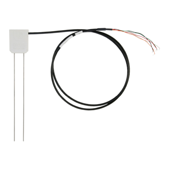
They output an SDI-12 signal that many Campbell Scientific dataloggers can measure. The CS650 has 30 cm length rods, whereas the CS655 has 12 cm length rods. This manual uses CS650 to reference model numbers CS650 and CS655. - Page 13 Open Short Cut and click Create New Program. Double-click the datalogger model. In the Available Sensors and Devices box, type CS650. You can also locate the sensor in the Sensors | Meteorological | Soil Moisture | CS650/CS655 Water Content Reflectometer folder. The four different options monitor different parameters.
- Page 14 CS650 and CS655 Water Content Reflectometers In Output Setup, type the scan rate. If you chose to measure the CS650 hourly rather than every scan, this scan interval must be evenly divisible into an hour. Type a meaningful table name and type the Data Output Storage Interval.
-
Page 15: Overview
Volumetric water content (VWC) is derived from the sensor sensitivity to the dielectric permittivity of the medium surrounding the sensor stainless-steel rods. The CS650 is configured as a water content reflectometer, with the two parallel rods forming an open-ended transmission line. A differential oscillator circuit is connected to the rods, with an oscillator state change triggered by the return of a reflected signal from one of the rods. -
Page 16: Specifications
Sensor electronics are encapsulated in the rugged epoxy sensor head. A five-conductor cable including the drain or shield wire provides power and ground as well as communications with the CS650. The CS650 is intended to communicate with SDI-12 recorders, including Campbell Scientific dataloggers. -
Page 17: Electrical Specifications
135 µA @ 12 Vdc Average Current Drain: I = 0.09n + [3.5 + 0.024(n-1)]n/s I = average current in milliamps n = number of CS650s s = number of seconds between measurements (see FIGURE 6-1) Campbell Scientific recommends using separate terminals when possible. -
Page 18: Operational Specifications
FIGURE 6-1. CS650 and CS655 average current drain FIGURE shows average current drain for different measurement rates and quantities of CS650 sensors. If the time between measurements is five minutes or longer, average current drain is approximately 0.15 milliamps per sensor. Operational Specifications TABLE provides the operational specifications. -
Page 19: Installation
EC along the length of the rods, which is 30 cm for the CS650 and 12 cm for the CS655. The sensor rods can insert vertically into the soil surface or buried at any orientation to the surface. Install the sensor horizontal to the surface to detect the passing of wetting fronts or other vertical water fluxes. -
Page 20: Proper Insertion
FIGURE 7-1. CS650G Rod Insertion Guide Tool with Pilot Rod Datalogger Wiring Campbell Scientific dataloggers typically use SDI-12 to measure the sensor because RS-232 communications require more terminals per CS650 and RS-232 programming is more complicated than SDI-12 programming. -
Page 21: Programming
For the CR6 and CR1000X dataloggers, triggering conflicts may occur when a companion terminal is used for a triggering instruction such as TimerInput(), PulseCount(), or WaitDigTrig(). For example, if the CS650 is connected to C3 on a CR1000X, C4 cannot be used in the TimerInput(), PulseCount(), or WaitDigTrig() instructions. -
Page 22: Operation
Operation A200 and Device Configuration Utility The A200 Sensor-to-Computer Interface allows communications between a CS650 and a computer to change sensor settings through Device Configuration Utility software. 8.1.1 Using the A200 8.1.1.1 Driver Installation If the A200 has not been previously plugged into your computer and your computer operating system is not Windows 7, the A200 driver needs to be installed. -
Page 23: Powering The Sensor
It is included in installations of LoggerNet, PC400, or RTDAQ. Connect the CS650 to the A200 as shown in TABLE 8-1. Connect the computer to the A200 USB port with the supplied USB cable. Launch Device Configuration Utility and search for CS650 Series from the... -
Page 24: Settings Editor Tab
Select Ok then Connect to begin communications with the CS650. 8.1.2.1 Settings Editor Tab The Settings Editor tab shows settings stored in the CS650 operating system. Settings that may be modified include User Name, SDI-12 Address, and RS- 232 Baud Rate. Attempts to change any of the other settings results in a “Commit failed. - Page 25 CS650 and CS655 Water Content Reflectometers Default communications settings are 9600 baud, no parity, 1 stop bit, 8 data bits, and no error checking. After any changes to CS650 settings, select Apply to write the changes to the CS650 operating system. A configuration summary is then shown.
- Page 26 CS650 and CS655 Water Content Reflectometers...
-
Page 27: Send Os Tab
Voltage Ratio 8.1.2.2 Send OS Tab The Send OS tab is used to update the operating system in the CS650. The operating system is available at www.campbellsci.com/downloads. The file to send has a filename extension of .a43, such as CS65X.Std.04.36.a43. Sending a new operating system does not affect any of the user-modified settings or sensor specific multiplier and offset settings. -
Page 28: M3! And M4! Commands
U terminal. Each must have a unique SDI-12 address. Valid addresses are 0 through 9, A through Z, and a through z. The CS650 ships with a default SDI-12 address of 0 unless otherwise specified at the time of ordering. Change the SDI-12 address through Device Configuration Utility (see Section 8.1,... - Page 29 M3! command reports NAN for permittivity. Permittivity < 1 If the CS650 calculates a permittivity value greater than zero but less than 1, the M3! command reports a permittivity value of 1. Permittivity too low for the Topp et al equation The Topp et al (1980) equation used by the CS650 to estimate volumetric water content works well for most mineral soils.
-
Page 30: Use Of Multiplexers
CS650 and CS655 Water Content Reflectometers CS650. For the CS655, the upper limit for bulk EC is 3.04 dS/m, corresponding to a solution EC of 8 dS/m. When this bulk EC condition occurs, the soil is considered out-of-bounds and the M3! command reports NAN or 9999999 for both permittivity and volumetric water content. -
Page 31: Topp Equation
–6 Research has shown that this equation works well in most mineral soils, so a soil specific calibration of the CS650 sensor is usually not necessary. For a soil specific calibration, you can generate an equation relating K to θ... -
Page 32: Temperature Correction Of Soil Electrical Conductivity
EC is outside the operational range of the sensor. 8.3.3.2 Temperature Correction of Soil Electrical Conductivity The EC value reported by the CS650 is bulk electrical conductivity. This value is temperature dependent, changing by 2% per degree Celsius. To compensate for the effect of temperature, convert EC readings to a standard temperature, such as 25 °C using the following equation:... -
Page 33: Temperature Dependence And Correction
8.3.5 Temperature Dependence and Correction The two temperature dependent sources of error in CS650 water content measurements are the effect of temperature on the operation of the sensor electronics and the effect of temperature on the dielectric permittivity of the soil. -
Page 34: User-Derived Calibration Equation
CS650 and CS655 Water Content Reflectometers In these cases, the user may develop a calibration equation to convert CS650 permittivity to volumetric water content over the range of water contents the sensor is expected to measure. 8.4.2 User-Derived Calibration Equation A quadratic equation or third order polynomial can describe the relationship between soil permittivity and volumetric water content. - Page 35 Non-metal container such as a PVC pipe (20 cm diameter, 35 cm • length) with one end closed. The container should be large enough to ensure that only soil is within 10 cm (4 in) of the CS650 rod surface. • Oven or microwave safe container of known weight Scale to measure soil sample mass •...
- Page 36 Add water to top of the container. Cover the container to prevent evaporation. Frequently observe the CS650 permittivity output, waiting for the permittivity to be constant. This indicates equilibration. The time required for equilibration depends on the amount of water added and the hydraulic properties of the soil.
-
Page 37: Collecting Field Data For Calibration
Oven or microwave to dry samples • Data needed for CS650 calibration are the CS650 permittivity output and an independently determined volumetric water content. From this data, the sensor response to changing water content can be described by a function as described in Section 8.4.2, User-Derived Calibration Equation... - Page 38 The following is the procedure for obtaining samples. Use a shovel to form a vertical face of soil. If using the CS650 within about 0.5 meters of the surface, insert the sensor into the face. Add water to the surface using percolation.
-
Page 39: Calculations
= θ • ρ bulk The average water content for the replicates and the recorded CS650 period are one datum pair to be used for the calibration curve fit. 8.4.5 Calculations The empty cylinders used for core sampling should be clean and both empty mass and volume are measured and recorded. -
Page 40: Maintenance And Troubleshooting
Volumetric water content is calculated using θ = θ • ρ bulk Maintenance and Troubleshooting The CS650 does not require periodic maintenance. TABLE provides troubleshooting information. TABLE 9-1. Symptom, Cause, and Solutions Symptom Possible Cause Solution All CS650 output... -
Page 41: References
CS650 and CS655 Water Content Reflectometers TABLE 9-1. Symptom, Cause, and Solutions Symptom Possible Cause Solution VWC reading is Soil bulk permittivity Modify program to 9999999 is outside sensor collect permittivity value operational range and try soil specific calibration EC reading is 9999999... -
Page 42: Importing Short Cut Code Into Crbasic Editor
Appendix A. Importing Short Cut Code Into CRBasic Editor This tutorial shows: Importing a Short Cut program into a program editor for additional • refinement Importing a wiring diagram from Short Cut into the comments of a • custom program Short Cut creates files, which can be imported into CRBasic Editor. -
Page 44: Example Programs
15 minutes, storing hourly averages of volumetric water content, electrical conductivity, and soil temperature and samples of permittivity, period average and voltage ratio. The CS650 has an SDI-12 address of 0. Wiring for the example is shown in TABLE B-1. -
Page 45: Cr1000X With Two Cs650 Sensors On Same Control Port
The first CS650 has an SDI-12 address of 0 and the second has an address of 1. Wiring for the example is shown in TABLE B-2. -
Page 46: Cr1000X Wiring For Multiplexer Example Program
COM Ground High Terminals 1H – 12H Low Terminals 1L – 12L Green Ground Terminals to Left of Black, Orange, Clear Low Terminals CRBasic Example B-3. CR1000X with 12 CS650 Sensors on Multiplexer LCount Public CS650(12,6) DataTable (DatoutCS650,1,-1) DataInterval (0,60,Min,2) -
Page 47: Cr200X With Three Cs650 Sensors
Appendix B. Example Programs B.2 CR200X with Three CS650 Sensors This CRBasic example program measures three CS650 sensors on a CR200X every 15 minutes, storing hourly averages of volumetric water content, electrical conductivity, soil temperature, permittivity, period average, and voltage ratio. The CS650s have SDI-12 addresses of 0, 1, and 2, respectively. - Page 48 Appendix C. Discussion of Soil Water Content The water content reflectometer measures volumetric water content. Soil water content is expressed on a gravimetric and a volumetric basis. To obtain the independently determined volumetric water content, gravimetric water content must first be measured. Gravimetric water content (θg) is the mass of water per mass of dry soil.
-
Page 50: Sdi-12 Sensor Support
Only three wires are necessary — serial data, ground, and 12 V. With unique addresses, multiple SDI-12 sensors can connect to a single SDI-12 terminal on a Campbell Scientific datalogger. This appendix discusses the structure of SDI-12 commands and the process of querying SDI-12 sensors. -
Page 51: Acknowledge Active Command (A
Appendix D. SDI-12 Sensor Support TABLE D-1. Campbell Scientific Sensor SDI-12 Command and Response Set Name Command Response a<values><CR><LF> aD0!...aD9! Send Data a<values><CRC><CR><LF> Information on each of these commands is given in following sections. D.2.1 Acknowledge Active Command (a!) The Acknowledge Active command (a!) is used to test a sensor on the SDI-12 bus. -
Page 52: Address Query Command
Appendix D. SDI-12 Sensor Support D.2.4 Address Query Command (?!) Command ?! requests the address of the connected sensor. The sensor replies to the query with the address, a. This command should only be used with one sensor on the SDI-12 bus at a time. D.2.5 Change Address Command (aAb!) Multiple SDI-12 sensors can connect to a single SDI-12 terminal on a datalogger. -
Page 53: Start Measurement Commands With Cyclic Redundancy Check (Amc
Appendix D. SDI-12 Sensor Support D.2.7 Start Measurement Commands with Cyclic Redundancy Check (aMC! !) Error checking is done by using measurement commands with cyclic redundancy checks (aMC!). This is most commonly implemented when long cable lengths or electronic noise may impact measurement transmission to the datalogger. -
Page 54: Changing An Sdi-12 Address
Transparent mode is entered while the computer is communicating with the datalogger through a terminal emulator program. It is accessed through Campbell Scientific datalogger support software or other terminal emulator programs. Datalogger keyboards and displays cannot be used. The terminal emulator is accessed by navigating to the Datalogger list in PC200W, the Tools list in PC400, or the Datalogger list in the Connect screen of LoggerNet. -
Page 55: Changing An Sdi-12 Address - Cr200(X) Series
Appendix D. SDI-12 Sensor Support 11. To exit SDI-12 transparent mode, click Close Terminal. FIGURE D-1. CR1000 example of using the SDI-12 transparent mode to change the SDI-12 address from 0 to 3. Sensor is connected to control port 1. D.3.2 Changing an SDI-12 Address –... -
Page 56: References
Appendix D. SDI-12 Sensor Support 10. To change the SDI-12 address, type aAb!, where a is the current address from the above step and b is the new address (see FIGURE D-1). Press Enter. The sensor changes its address and responds with the new address. 11. - Page 59 Campbell Scientific Worldwide Offices Australia Germany Location: Garbutt, QLD Australia Location: Bremen, Germany Email: Email: info@campbellsci.com.au info@campbellsci.de Website: www.campbellsci.com.au Website: www.campbellsci.de Brazil South Africa Location: São Paulo, SP Brazil Location: Stellenbosch, South Africa Email: andread@campbellsci.com.br Email: sales@csafrica.co.za Website: Website: www.campbellsci.com.br www.campbellscientific.co.za...
Need help?
Do you have a question about the CS650 and is the answer not in the manual?
Questions and answers