Campbell CNR4 Product Manual
Net radiometer
Hide thumbs
Also See for CNR4:
- Instruction manual (70 pages) ,
- User manual (60 pages) ,
- Product manual (52 pages)
Table of Contents
Advertisement
Quick Links
Advertisement
Table of Contents

Related Manuals for Campbell CNR4


Summary of Contents for Campbell CNR4
- Page 1 Revision: 06/2021 Copyright © 2000 – 2021 Campbell Scientific, Inc.
-
Page 2: Table Of Contents
Table of contents 1. Introduction 2. Precautions 3. Initial inspection 3.1 Ships with 4. QuickStart 5. Overview 6. Specifications 6.1 CNR4 specifications 6.2 Pyranometer specifications 6.3 Pyrgeometer specifications 6.4 Optional CNF4 heater/ventilator 6.4.1 CNF4 specifications 7. Installation 7.1 Siting considerations 7.2 Mounting 7.3 Wiring... - Page 3 9.2.2 Replacing the drying cartridge 9.3 Recalibration Appendix A. Importing Short Cut code into CRBasic Editor Appendix B. CNR4 performance and measurements under different conditions 31 Appendix C. CNF4 heater ventilator C.1 General information C.2 Attaching the optional CNF4 heater/ventilator unit to CNR4 C.3 Wiring...
-
Page 4: Introduction
Safety section at the back of this manual. Although the CNR4 is rugged, it is also a highly precise scientific instrument and should be handled as such. Care should be taken when opening the shipping package to not damage or cut the cable jacket. -
Page 5: Quickstart
1. Open Short Cut and click Create New Program. 2. Double-click the data logger model. 3. In the Available Sensors and Devices box, type CNR4 or locate the sensor in the Sensors > Meteorological > Solar Radiation folder. Double-click CNR4 Net Radiation. Type the sensitivity values supplied on the manufacturer certificate of calibration;... - Page 6 4. Click on the Wiring tab to see how the sensor is to be wired to the data logger. Click OK after wiring the sensor. 5. Repeat steps three and four for other sensors. Click Next. CNR4 Net Radiometer 3...
- Page 7 9. If the sensor is connected to the data logger, check the output of the sensor in the data logger support software data display in LoggerNet, RTDAQ, or PC400 to make sure it is making reasonable measurements. CNR4 Net Radiometer 4...
-
Page 8: Overview
The upper long-wave detector of CNR4 has a meniscus dome to ensure that water droplets roll off easily while improving the field of view to nearly 180°, compared with a 150° for a flat window. -
Page 9: Specifications
CR1000 6. Specifications The properties of the CNR4 are mainly determined by the properties of the individual probes. Generally, the accuracy of the CNR4 will be higher than that of competitive net-radiometers, because the solar radiation measurement performed by the pyranometer is accurate, and offers a traceable calibration. -
Page 10: Cnr4 Specifications
FIGURE 6-1. The CNR4 net radiometer with cables and mounting rod, top view FIGURE 6-2. The CNR4 net radiometer with CNF4 heater/ventilator unit, top view 6.1 CNR4 specifications Sensor sensitivities: Four probes with unique sensitivity values. Please refer to the calibration sheets or label on the bottom of the sensor for the sensitivity values. -
Page 11: Pyranometer Specifications
< 1 W/m (with CNF4 installed) Operating temperature: –40 to 80 °C Field of view Upper detector: 180° Lower detector: 150° (due to lower solar shield to prevent illumination at low zenith angles) Maximum solar irradiance: 2000 W/m CNR4 Net Radiometer 8... -
Page 12: Pyrgeometer Specifications
±4 W/m (5 K/hr temperature change) Field of view Upper: 180 degrees Lower: 150 degrees Net-irradiance: –250 to +250 W/m Non-stability: < 1% (sensitivity change per year) Window heating offset: < 6 W/m (1000 W/m solar irradiance) CNR4 Net Radiometer 9... -
Page 13: Optional Cnf4 Heater/Ventilator
–40 to 80 °C 7. Installation If you are programming your data logger with Short Cut, skip Wiring (p. 13) and Data logger programming (p. 17). Short Cut does this work for you. See QuickStart (p. 2) for a tutorial. CNR4 Net Radiometer 10... -
Page 14: Siting Considerations
For example, in the Northern Hemisphere, point the cable toward the North Pole. 7.2 Mounting A mounting bracket kit is used to mount the CNR4 directly to a vertical pipe, or to a crossarm. Mount the sensor as follows: 1. Attach the mounting rod to the CNR4 (see FIGURE 7-1 (p. - Page 15 This includes both the incoming and outgoing sections of the sensor. FIGURE 7-2. Attaching the CNR4 onto the mounting rod using vertical pole or horizontal crossarm CNR4 Net Radiometer 12...
-
Page 16: Wiring
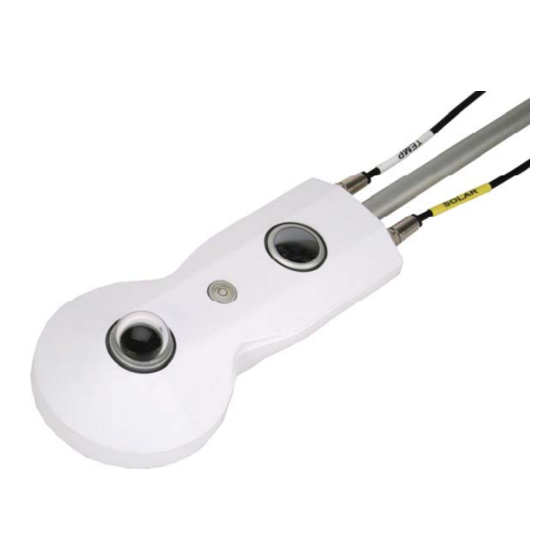
FIGURE 7-2 (p. 12)). NOTE: If the CNR4 is being used at a location where snow and ice accumulate, or high winds are expected, then the mounting rod should not be fully extended. CAUTION: Do not attempt to rotate the instrument using the sensor heads, or you may damage the sensors;... - Page 17 FIGURE 7-3. The CNR4 sensor with SOLAR and TEMP cables FIGURE 7-4. The marks on the end of the CNR4: S for SOLAR cable, and T for TEMP cable The four radiation outputs can be measured using differential or single-ended inputs on the data logger.
- Page 18 , DIFF H (differential analog input , SE (single-ended, top signal high, analog-voltage input) analog-voltage input) U configured for differential low Pyrgeometer Yellow analog input , 2, DIFF L (differential ⏚ (analog ground) top reference low, analog-voltage input)2 CNR4 Net Radiometer 15...
- Page 19 U configured for differential high PRT (Pt-100) Green analog input , DIFF H (differential signal high, analog-voltage input) PRT (Pt-100) U configured for differential low Yellow signal analog input , DIFF L (differential reference low, analog-voltage input) CNR4 Net Radiometer 16...
-
Page 20: Data Logger Programming
FIGURE 7-6. Labels on the pigtail end of the TEMP cable 7.4 Data logger programming Short Cut is the best source for up-to-date programming code for Campbell Scientific data loggers. If your data acquisition requirements are simple, you can probably create and maintain a data logger program exclusively with Short Cut. -
Page 21: Sensor Sensitivity
± 5 mV for the pyrgeometers. 7.4.1 Sensor sensitivity The CNR4 comes with four different sensor sensitivity values for four separate probes. The CNR4 sensor comes with two copies of its ‘Certificate of Calibration’ by the manufacturer. They show the sensor serial number and sensitivity values for four individual probes: one copy for pyranometers, and another copy for pyrgeometers. -
Page 22: Operation
The pyranometer generates a millivolt signal that is simply proportional to the incoming short- wave radiation. The conversion factor between voltage, V, and W/m of solar irradiance E, is the calibration constant C or sensitivity (Eq. 1 (p. 20)). For each pyranometer, CNR4 Net Radiometer 19... -
Page 23: Long-Wave Far Infrared Radiation Measurements
T, into account. This is why the temperature sensors are incorporated in the CNR4 body near the pyrgeometer sensing element, and has, therefore, the same temperature as the pyrgeometer sensor surface. -
Page 24: Internal Temperature Sensors Measurements
8.3 Internal temperature sensors measurements The CNR4 has two temperature sensors built inside: thermistor and Pt-100; both have identical accuracy. The thermistor is recommended when using Campbell Scientific data loggers. The thermistor has a greater resistance (10 kΩ at 25 °C) than Pt-100 sensor (100 Ω at 0 °C), and the change in resistance with respect to temperature, in absolute terms, is greater. - Page 25 8523 2854 Relatively small errors occur when the CNR4 is not in thermal equilibrium. This happens for example when the heater is on, or when the sun is shining. When the heater and ventilator are on, the largest expected deviation between the real sensor temperature and the thermistor reading is 1 degree.
- Page 26 Table 8-2: Resistance values versus CNR4 Pt–100 temperature in °C Temperature Resistance Temperature Resistance Temperature Resistance [°C] [°C] [°C] –30 88.22 100.00 111.67 –29 88.62 100.39 112.06 –28 89.01 100.78 112.45 –27 89.40 101.17 112.83 –26 89.80 101.56 113.22 –25 90.19...
-
Page 27: Calculation Of Albedo
Table 8-2: Resistance values versus CNR4 Pt–100 temperature in °C Temperature Resistance Temperature Resistance Temperature Resistance [°C] [°C] [°C] –4 98.44 110.12 121.70 –3 98.83 110.51 122.09 –2 99.22 110.90 122.47 –1 99.61 111.28 122.86 8.4 Calculation of albedo Albedo is the ratio of reflected short-wave radiation to incoming short-wave radiation. This unitless value ranges between 0 and 1. -
Page 28: Calculation Of Net Long-Wave Radiation
T, cancel each other. Therefore, if only interested in the net long-wave radiation, instead of separate upper and lower components of the long-wave radiation, the CNR4 temperature measurement is not required. The E measured with the pyrgeometer actually represents the irradiance of the sky (for upward- facing pyrgeometer) or the ground (for downward-facing pyrgeometer). -
Page 29: Troubleshooting And Maintenance
Before starting the second test measurement, let the pyranometer rest for at least five minutes to let it regain its thermal equilibrium. For testing, set a voltmeter to its most sensitive range setting. Darken the sensor. The signal should read zero; this response can take up to one minute. Small CNR4 Net Radiometer 26... -
Page 30: Testing The Pyrgeometer
Testing the pyranometer (p. 26)). The CNR4 body and the ambient air should be at the same temperature. Let the pyrgeometer rest for at least five minutes to regain its thermal equilibrium. Set the voltmeter to its most sensitive range. To test if the pyrgeometer is working properly, put your hand in front of the pyrgeometer. -
Page 31: Testing The Pt-100
Dirty domes and windows can reduce the radiometer readings. The site operator should check the windows and domes of the CNR4 regularly, and clean them as needed. Use distilled water or alcohol as cleaning solution, being careful not to scratch the windows and domes during cleaning. -
Page 32: Recalibration
Kipp & Zonen calibration facility. The CNR4 should be recalibrated every two years. Alternatively, one can check the sensor calibration by letting a higher standard run parallel to it over a two-day period and, then, comparing the results. -
Page 33: Appendix A. Importing Short Cut Code Into Crbasic Editor
Block. This adds an apostrophe (') to the beginning of each of the highlighted lines, which instructs the data logger compiler to ignore those lines when compiling. The Comment Block feature is demonstrated at about 5:10 in the CRBasic | Features video CNR4 Net Radiometer 30... -
Page 34: Appendix B. Cnr4 Performance And Measurements Under Different Conditions
This can roughly be attributed to the water vapor in the air, which is a major contributor to the far infrared radiation. Table B-1: Typical output signals of CNR4 under different meteorological conditions. Explanation can be found in the text. - Page 35 Table B-1: Typical output signals of CNR4 under different meteorological conditions. Explanation can be found in the text. –100 clear –100 –53 clear –20 –20 –20 Values may suffer from the so-called window heating offset; the sun heats the pyrgeometer window causing a measurement error of +10 Watts per square meter (maximum).
- Page 36 FIGURE B-2. Partly cloudy day for the upward facing pyrgeometer FIGURE B-3. Clear day for the downward facing pyrgeometer CNR4 Net Radiometer 33...
- Page 37 The sky and the ground temperature can be calculated from the measured values of the sensors using formulas Eq. 9 (p. 34) and Eq. 10 (p. 34) below. Eq. 9 CNR4 Net Radiometer 34...
-
Page 38: Appendix C. Cnf4 Heater Ventilator
In such a case, the heater should be used because the error described above is significantly smaller than the gain obtained by heating the sensor to avoid the dew deposition. Please refer to the following diagram to determine whether or not the heater should be used. CNR4 Net Radiometer 35... - Page 39 1 hour after sunrise. The heater power can be controlled using one of the SW12V terminals of the Campbell Scientific data loggers. The heater current drain is approximately 850 mA at 12 VDC (10 W). The ventilator draws additional 5 W of power at 12 VDC. Connect the power ground from the heater to a G terminal close to the SW12V terminal of the data logger (not to an analog ground near the measurement inputs).
-
Page 40: Attaching The Optional Cnf4 Heater/Ventilator Unit To Cnr4
C.2 Attaching the optional CNF4 heater/ventilator unit to CNR4 1. The CNF4 heater/ventilator unit comes with the following: the heater/ventilator, the white solar shield, three pan-head screws with washers, and four flat-head screws as shown in FIGURE C-1 (p. 37). - Page 41 2. Attach the heater/ventilator unit unto the bottom of the CNR4 sensor, using the three pan- head screws and washers, as shown in FIGURE C-2 (p. 38). Make sure that the pyranometer and the pyrgeometer windows are not scratched during the installation.
- Page 42 CNF4, as shown in FIGURE C-4 (p. 39) and FIGURE C-5 (p. 40). FIGURE C-3. Making sure the cables are clear from the edges FIGURE C-4. CNF4 solar shield and four flat-head screws CNR4 Net Radiometer 39...
- Page 43 FIGURE C-5. Attaching the solar shield to CNF4 using four flat-head screws 4. Once the CNF4 heater/ventilator unit is attached to the bottom side of the CNR4, the CNF4 will cover the label that contains the serial number and the sensitivity values for the four sensors.
-
Page 44: Wiring
Depending on the data logger that is used with the CNR4-L and the older, four-wire version of the CNF4-L, the tachometer output may not work for 25-m (82-ft) or 50-m (164-ft) cables. - Page 45 Do not use the data logger switched 12 V to simultaneously power the heater and ventilator. Simultaneously powering the heater and ventilator will exceed the current limit of the switched 12 V terminal. If the heater and ventilator need to be used at the same time, connect CNR4 Net Radiometer 42...
-
Page 46: Data Logger Programming For Heater/Ventilator Control
The SW12 terminal cannot provide enough amperage for the CNF4. Therefore, the CNR4 should be connected to the 12V terminal. An A21REL-12 can be used to switch 12V to reduce current consumption. An example program that measures the CNR4,... -
Page 47: Replacing The Filter For The Ventilator
Inspect the filter for dust and particles that might impede the air flow into the ventilator. The filter can be cleaned with warm clean water, or can be replaced with the new one. You can purchase the replacement filters from Campbell Scientific. CNR4 Net Radiometer 44... - Page 48 See Product Details on the Ordering Information pages at www.campbellsci.com . Other manufacturer's products, that are resold by Campbell Scientific, are warranted only to the limits extended by the original manufacturer. Refer to www.campbellsci.com/terms#warranty for more information.
- Page 49 To obtain a Returned Materials Authorization or Repair Reference number, contact your CAMPBELL SCIENTIFIC regional office. Please write the issued number clearly on the outside of the shipping container and ship as directed. For all returns, the customer must provide a “Statement of Product Cleanliness and Decontamination”...
- Page 50 Do not recharge, disassemble, heat above 100 °C (212 °F), solder directly to the cell, incinerate, or expose contents to water. Dispose of spent batteries properly. WHILE EVERY ATTEMPT IS MADE TO EMBODY THE HIGHEST DEGREE OF SAFETY IN ALL CAMPBELL SCIENTIFIC PRODUCTS, THE CUSTOMER ASSUMES ALL RISK FROM ANY INJURY RESULTING FROM IMPROPER INSTALLATION, USE, OR MAINTENANCE OF TRIPODS, TOWERS, OR...
- Page 51 Campbell Scientific Regional Offices Australia France Thailand Location: Garbutt, QLD Australia Location: Vincennes, France Location: Bangkok, Thailand Phone: 61.7.4401.7700 Phone: 0033.0.1.56.45.15.20 Phone: 66.2.719.3399 Email: info@campbellsci.com.au Email: info@campbellsci.fr Email: info@campbellsci.asia Website: www.campbellsci.com.au Website: www.campbellsci.fr Website: www.campbellsci.asia Brazil Germany Location: São Paulo, SP Brazil...
Need help?
Do you have a question about the CNR4 and is the answer not in the manual?
Questions and answers