
Subscribe to Our Youtube Channel
Related Manuals for Campbell 03002 R.M


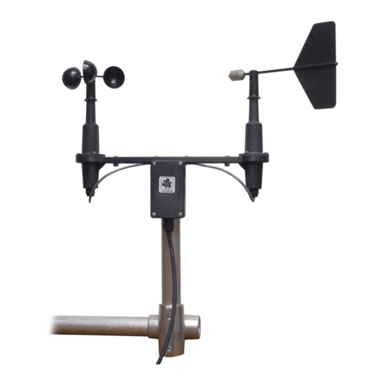
Summary of Contents for Campbell 03002 R.M
- Page 1 03002 R.M. Young Wind Sentry Set 03101 R.M. Young Wind Sentry Anemometer 03301 R.M. Young Wind Sentry Vane Revision: 9/13 C o p y r i g h t © 1 9 8 6 - 2 0 1 3 C a m p b e l l S c i e n t i f i c , I n c .
- Page 3 Campbell pricelist or product manual. Products not manufactured, but that are re-sold by Campbell, are warranted only to the limits extended by the original manufacturer. Batteries, fine-wire thermocouples, desiccant, and other consumables have no warranty.
- Page 4 SCIENTIFIC, INC., phone (435) 227-9000. After an application engineer determines the nature of the problem, an RMA number will be issued. Please write this number clearly on the outside of the shipping container. Campbell Scientific's shipping address is: CAMPBELL SCIENTIFIC, INC.
-
Page 5: Table Of Contents
Table of Contents PDF viewers: These page numbers refer to the printed version of this document. Use the PDF reader bookmarks tab for links to specific sections. 1. Introduction ..............1 2. Cautionary Statements..........1 3. Initial Inspection ............1 Ships With List..................2 4. - Page 6 Table of Contents 9. Troubleshooting............18 Wind Direction .................. 18 Wind Speed ..................18 10. References..............19 Appendices A. Wind Direction Sensor Orientation .......A-1 Determining True North and Sensor Orientation ......A-1 B. Wind Direction Measurement Theory....B-1 BRHalf Instruction ................B-1 EX-DEL-SE (P4) Instruction............B-1 Figures 4-1.
-
Page 7: Introduction
File damage claims with the shipping company. Immediately check package contents against the shipping documentation (see Section 3.1, Ships With List). Contact Campbell Scientific about any discrepancies. • The model number and cable length are printed on a label at the connection end of the cable. -
Page 8: Ships With List
R.M. Young Wind Sentry Ships With List The 03002 Wind Sentry ships with: (1) 03002 Wind Sentry including 03102 anemometer 03302 vane crossarm band clamp (pn 4919) (1) 12" x 1.0" unthreaded aluminium pipe (pn 3659) (1) Allen wrench (pn 5201) The 03101 anemometer ships with: (1) 03101 anemometer (1) 10"... -
Page 9: Cm200-Series Crossarm With Cm220 Right Angle Mounting Bracket
R.M. Young Wind Sentry 1. Install the cup wheel to the anemometer shaft using the Allen wrench provided with the sensor. 2. Mount a CM202, CM204, or CM206 crossarm to the tripod or tower. 3. Orient the crossarm North-South, with the CM220 mount or 17953 NU- RAIL on the north end. -
Page 10: 03002 Mounted To Cm200-Series Crossarm With Cm220
R.M. Young Wind Sentry Alumimum Pipe CM220 CM200-Series Crossarm FIGURE 4-2. 03002 mounted to CM200-Series Crossarm with CM220 pn 17953 NU-RAIL Aluminum Pipe CM200-Series Crossarm Cable Tie FIGURE 4-3. 03002 mounted to CM200-Series Crossarm with pn 17953... -
Page 11: Step 2 - Use Scwin Short Cut To Program Datalogger And Generate Wiring Diagram
Generate Wiring Diagram The simplest method for programming the datalogger to measure the 03002 is to use Campbell Scientific's SCWin Short Cut Program Generator. 1. Open Short Cut and click on New Program. 2. Select the Datalogger and enter the Scan Interval and select Next. - Page 12 R.M. Young Wind Sentry 3. Select 03002 Wind Speed & Direction Sensor and select the right arrow (in center of screen) to add it to the list of sensors to be measured then select Next. 4. Select Wind Vector for the output and then select Finish.
-
Page 13: Overview
Wind speed is measured with a three cup anemometer. Rotation of the cup wheel produces an ac sine wave voltage with frequency proportional to wind speed. This is a special version of the 03102 built for Campbell Scientific by R.M. Young that has shielded bearings rather than sealed bearings. The shielded bearings provide a lower starting threshold than sealed bearings. -
Page 14: Specifications
R.M. Young Wind Sentry The 03002's cable can terminate in: • Pigtails that connect directly to a Campbell Scientific datalogger (option –PT). • Connector that attaches to a prewired enclosure (option –PW). Refer www.campbellsci.com/prewired-enclosures for more information. • Connector that attaches to a CWS900 Wireless Sensor Interface (option –CWS). -
Page 15: Wind Direction (Vane)
R.M. Young Wind Sentry –1 Threshold: 0.5 m s (1.1 mph) Transducer: Stationary coil, 1300 ohm nominal resistance Output: AC sine wave signal induced by rotating magnet on cup wheel shaft 100 mV peak-to-peak at 60 rpm; 6 V peak-to-peak at 3600 rpm –1 Output Frequency:... -
Page 16: Assembly And Mounting
R.M. Young Wind Sentry Assembly and Mounting Assembly and Mounting Tools required: Tools required: • • 5/64” Allen wrench 5/64” Allen wrench • • Allen wrench provided with sensor Allen wrench provided with sensor • • 1/2” open end wrench 1/2”... -
Page 17: 03301 Vane
1049), and the mounting pipe that ships with the sensor. Wiring Connections to Campbell Scientific dataloggers are given in TABLE 7-1 and TABLE 7-2. When Short Cut is used to create the datalogger program, the sensor should be wired to the channels shown on the wiring diagram created by... -
Page 18: 03002-L Wiring
R.M. Young Wind Sentry TABLE 7-1. 03002-L Wiring CR800 CR5000 CR21X CR3000 CR510 Color Description CR1000 CR10(X) CR23X CR200(X) Wind Spd. Signal Pulse Pulse Pulse P_LL Black Wind Spd. Reference Clear Shield White Wind Dir. Reference Green Wind Dir. Signal SE Analog SE Analog SE Analog... -
Page 19: Programming
All other CRBasic dataloggers use the BRHalf() instruction. Edlog dataloggers (CR510, CR10X, CR23X) use Edlog Instruction 4—Excite, Delay (P4). Excitation voltages, range codes, and multipliers for Campbell Scientific dataloggers are listed in TABLE 7-4. Appendix B has additional information on the BRHalf() measurement instructions. -
Page 20: Wind Vector Processing Instruction
R.M. Young Wind Sentry TABLE 7-4. Parameters for Wind Direction CR10(X) CR510 CR800 CR5000 CR200(X) CR23X CR1000 CR3000 Measurement 2500 mV, 5000 mV, 2500 mV, 5000 mV, Range slow slow/60 Hz 60 Hz, 60 Hz, reverse reverse excitation excitation Excitation 2500 mV 5000 mV 2500 mV... -
Page 21: Cr1000 Program
R.M. Young Wind Sentry 7.4.4.1 CR1000 Program 'CR1000 'Declare Variables and Units Public Batt_Volt Public WS_ms Public WindDir Units Batt_Volt=Volts Units WS_ms=meters/second Units WindDir=Degrees 'Define Data Tables DataTable(Table1,True,-1) DataInterval(0,60,Min,10) WindVector (1,WS_ms,WindDir,FP2,False,0,0,0) FieldNames("WS_ms_S_WVT,WindDir_D1_WVT,WindDir_SD1_WVT") EndTable 'Main Program BeginProg Scan(5,Sec,1,0) 'Default Datalogger Battery Voltage measurement Batt_Volt: Battery(Batt_Volt) '03002 or 03101 RM Young Wind Sentry Wind Speed Sensor measurement - WS_ms: PulseCount(WS_ms,1,1,1,1,0.75,0.2) - Page 22 R.M. Young Wind Sentry ;If WS < starting threshold then set WS = 0 3: If (X<=>F) (P89) 1: 2 X Loc [ WS_ms 2: 4 < 3: 0.21 4: 30 Then Do 4: Z=F x 10^n (P30) 1: 0 2: 0 n, Exponent of 10 3: 2...
-
Page 23: Long Lead Lengths
Replace the potentiometer when the noise or nonlinearity becomes unacceptable. Contact Campbell Scientific for a Return Materials Authorization (RMA) number at (435) 227-9000. A “Statement of Product Cleanliness and Decontamination” form also needs to be filled out. -
Page 24: Troubleshooting
R.M. Young Wind Sentry Troubleshooting Wind Direction Symptom: NAN, –9999, or no change in direction Check that the sensor is wired to the excitation and single-ended channel specified by the measurement instruction. Verify that the excitation voltage and range code are correct for the datalogger type. -
Page 25: References
R.M. Young Wind Sentry 10. References The following references give detailed information on siting wind speed and wind direction sensors. EPA, 1989: Quality Assurance Handbook for Air Pollution Measurements System, Office of Research and Development, Research Triangle Park, NC, 27711. EPA, 1987: On-Site Meteorological Program Guidance for Regulatory Modeling Applications, EPA-450/4-87-013, Office of Air Quality Planning and Standards, Research Triangle Park, NC 27711. - Page 26 R.M. Young Wind Sentry...
-
Page 27: Wind Direction Sensor Orientation
Appendix A. Wind Direction Sensor Orientation A.1 Determining True North and Sensor Orientation Orientation of the wind direction sensor is done after the datalogger has been programmed, and the location of True North has been determined. True North is usually found by reading a magnetic compass and applying the correction for magnetic declination;... - Page 28 Appendix A. Wind Direction Sensor Orientation FIGURE A-1. Magnetic declination for the contiguous United States (2004)
-
Page 29: Declination Angles East Of True North Are Subtracted From 0 To
Appendix A. Wind Direction Sensor Orientation FIGURE A-2. Declination angles east of True North are subtracted from 0 to get True North FIGURE A-3. Declination angles west of True North are added to 0 to get True North... - Page 30 Appendix A. Wind Direction Sensor Orientation...
-
Page 31: Brhalf Instruction
Appendix B. Wind Direction Measurement Theory It is not necessary to understand the concepts in this section for the general operation of the 03002 with Campbell Scientific’s datalogger. EXCITATION VOLTAGE (V x ) SIGNAL + (V s ) AZIMUTH REFERENCE EARTH GROUND CONNECTION FIGURE B-1. - Page 32 Appendix B. Wind Direction Measurement Theory The maximum value that R will reach is R just before it crosses over from the west side of north to the east side of north (at this point R = 0). V reaches its maximum value of V .
- Page 33 METEOROLOGICAL INSTRUMENTS INSTRUCTIONS WIND SENTRY MODEL 03002-5 R.M. YOUNG COMPANY 2801 AERO PARK DRIVE, TRAVERSE CITY, MICHIGAN 49686, USA TEL: (231) 946-3980 FAX: (231) 946-4772 WEB: www.youngusa.com P/N: 03002-5-90 REV: D110210...
- Page 34 INTRODUCTION MODEL 03002-5 WIND SENTRY The Wind Sentry Anemometer and Vane measure horizontal wind speed and wind direction. The small size, simplicity, and corrosion INCLUDES MODELS 03102 & 03302 resistant construction provide a professional quality instrument at a modest cost. The cup wheel and vane shafts use stainless steel precision instrument grade ball bearings which are lubricated with a wide temperature range high quality instrument oil.
- Page 35 conditioning occurs at 352°. For example, in a circuit where 0 to FAILURE TO PROPERLY GROUND THE WIND SENTRY 1.00 VDC represents 0° to 360°, the output must be adjusted for MAY RESULT IN ERRONEOUS SIGNALS 0.978 VDC when the instrument is at 352° full scale. (352°/360° X OR TRANSDUCER DAMAGE.
- Page 36 WARRANTY 3. ALIGN VANE a) Connect excitation voltage and signal conditioning electronics to instrument according to wiring diagram. This product is warranted to be free of defects in materials and b) Loosen set screw in side of vane hub. construction for a period of 12 months from date of initial purchase. Liability is limited to repair or replacement of defective item.
- Page 37 CABLE & WIRING DIAGRAM 03002-5-90(D) Page 4...
- Page 38 GENERAL ASSEMBLY & REPLACEMENT PARTS 03002-5-90(D) Page 5...
- Page 40 Campbell Scientific Ltd. (CSL Germany) Fahrenheitstraße 13 28359 Bremen GERMANY www.campbellsci.de • info@campbellsci.de Campbell Scientific Spain, S. L. (CSL Spain) Avda. Pompeu Fabra 7-9, local 1 08024 Barcelona SPAIN www.campbellsci.es • info@campbellsci.es Please visit www.campbellsci.com to obtain contact information for your local US or international representative.
Need help?
Do you have a question about the 03002 R.M and is the answer not in the manual?
Questions and answers