Campbell 05103 Instruction Manual
R.m. young wind monitors
Hide thumbs
Also See for 05103:
- User manual (43 pages) ,
- Product manual (30 pages) ,
- Instruction manual (24 pages)

Related Manuals for Campbell 05103


Summary of Contents for Campbell 05103
- Page 1 05103, 05103-45, 05106, and 05305 R.M. Young Wind Monitors Revision: 10/13 C o p y r i g h t © 1 9 8 4 - 2 0 1 3 C a m p b e l l S c i e n t i f i c ,...
- Page 3 Campbell pricelist or product manual. Products not manufactured, but that are re-sold by Campbell, are warranted only to the limits extended by the original manufacturer. Batteries, fine-wire thermocouples, desiccant, and other consumables have no warranty.
- Page 4 SCIENTIFIC, INC., phone (435) 227-9000. After an application engineer determines the nature of the problem, an RMA number will be issued. Please write this number clearly on the outside of the shipping container. Campbell Scientific’s shipping address is: CAMPBELL SCIENTIFIC, INC.
-
Page 5: Table Of Contents
Table of Contents PDF viewers: These page numbers refer to the printed version of this document. Use the PDF reader bookmarks tab for links to specific sections. 1. Introduction ..............1 2. Cautionary Statements..........1 3. Initial Inspection ............1 Ships With....................2 4. Quickstart ..............2 Step 1 —... - Page 6 True North................A-3 A-3. Declination angles west of True North are added to 0 to get True North ................... A-3 B-1. 05103 potentiometer in a half bridge circuit........B-1 Tables 5-1. Recommended Lead Lengths .............. 6 7-1. Connections to Campbell Scientific Dataloggers ......10 7-2.
-
Page 7: Introduction
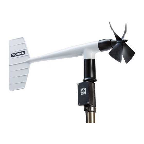
05103, 05103-45, 05106, and 05305 R.M. Young Wind Monitors Introduction The 05103, 05103-45, 05106, and 05305 Wind Monitor sensors are used to measure horizontal wind speed and direction. The 05305 is a high performance version of the 05103 designed to meet PSD specifications for air quality applications. -
Page 8: Ships With
(1) Instruction manual (1) 3659 mounting pipe Quickstart Step 1 — Mount the Sensor FIGURE 4-1 shows a 05103 installed with a 17953 Nurail® . Please review Section 7, Installation, for siting and other guidelines. Install the 05103 using: •... -
Page 9: Step 2 - Use Scwin Short Cut To Program Datalogger And Generate Wiring Diagram
Step 2 — Use SCWin Short Cut to Program Datalogger and Generate Wiring Diagram The simplest method for programming the datalogger to measure the Wind Monitor is to use Campbell Scientific’s SCWin Short Cut Program Generator. 1. Open Short Cut and click on New Program. - Page 10 05103, 05103-45, 05106, and 05305 R.M. Young Wind Monitors 2. Select the Datalogger Model and enter the Scan Interval. 3. Under Available Sensors and Devices, select your sensor, and select the right arrow to add it to the list of sensors to be measured then select next.
-
Page 11: Overview
05103, 05103-45, 05106, and 05305 R.M. Young Wind Monitors 4. Select WindVector for the output and then select Finish. 5. Wire according to the wiring diagram generated by SCWin Short Cut. Overview Wind speed is measured with a helicoid-shaped, four-blade propeller. Rotation of the propeller produces an AC sine wave signal with frequency proportional to wind speed. -
Page 12: Specifications
The Wind Monitors are manufacturered by R.M. Young and cabled by Campbell Scientific for use with our dataloggers. Lead lengths for the Wind Monitors are specified when the sensors are ordered. TABLE 5-1 gives the recommended lead length for mounting the sensor at the top of the tripod/tower with a CM200-series crossarm. - Page 13 05103, 05103-45, 05106, and 05305 R.M. Young Wind Monitors Wind Direction 05103-45 05103 Wind 05106 Wind Monitor- Wind 05305 Monitor Alpine Monitor-MA Wind Monitor-AQ Range 0° to 360° mechanical, 355° electrical (5° open) Accuracy ±3° ±5° ±3° –1 –1 Starting Threshold 1.1 m s...
-
Page 14: Installation
O.D.). A 12 inch long mounting pipe ships with the Wind Monitor for attaching the sensor to a CM200-series crossarm with the CM220 (FIGURE 7-1) or 1049 Nurail® fitting (FIGURE 4-1 in Quickstart section). The 05103 can also be mounted to a CM110 series tripod mast with the CM216 Mast Mounting Kit (see FIGURE 7-2). -
Page 15: Cm220 Right Angle Mounting Kit Mounted To A Crossarm
05103, 05103-45, 05106, and 05305 R.M. Young Wind Monitors CM220 CM200-Series Crossarm FIGURE 7-1. CM220 Right Angle Mounting Kit mounted to a crossarm FIGURE 7-2. The CM216 allows the wind monitor to mount atop a tripod... -
Page 16: Wiring
Programming This section is for users who write their own programs. A datalogger program to measure this sensor can be created using Campbell Scientific’s SCWin Short Cut Program Generator software. You do not need to read this section to use Short Cut. -
Page 17: Wind Direction
05103, 05103-45, 05106, and 05305 R.M. Young Wind Monitors The expression for wind speed (U) is: U = Mx + B where M = multiplier x = number of pulses per second (Hertz) B = offset TABLE 7-2 lists the multipliers to obtain miles/hour or meters/second when the measurement instruction is configured to output Hz. -
Page 18: Wind Vector Processing Instruction
(optional) using the measured wind speed and direction samples. 7.4.4 Example Programs The following programs measure the Wind Monitor 05103 every 5 seconds, and store mean wind speed, unit vector mean direction, and standard deviation of the direction every 60 minutes. Wiring for the examples is given in TABLE 7-4. -
Page 19: Cr10X Example Program
'Main Program BeginProg Scan(5,Sec,1,0) 'Default Datalogger Battery Voltage measurement Batt_Volt: Battery(Batt_Volt) '05103 Wind Speed & Direction Sensor measurements WS_ms and WindDir: PulseCount(WS_ms,1,1,1,1,0.098,0) BrHalf(WindDir,1,mV2500,1,1,1,2500,True,0,_60Hz,355,0) 'mV5000 'range, 5000 mV excitation for CR3000 and CR5000 dataloggers If WindDir>=360 Then WindDir=0 If WindDir<0 Then WindDir=0... -
Page 20: Long Lead Lengths
05103, 05103-45, 05106, and 05305 R.M. Young Wind Monitors 5: End (P95) 6: If time is (P92) 1: 0 Minutes (Seconds --) into a 2: 60 Interval (same units as above) 3: 10 Set Output Flag High (Flag 0) 7: Set Active Storage Area (P80) -
Page 21: Troubleshooting
05103, 05103-45, 05106, and 05305 R.M. Young Wind Monitors NOTE Often Campbell Scientific recommends factory replacement of the bearings and potentiometer. Refer to the Assistance page of this document for the procedure of acquiring a Returned Materials Authorization (RMA). Mechanically-adept users may choose to replace the bearings or potentiometer themselves. -
Page 22: References
05103, 05103-45, 05106, and 05305 R.M. Young Wind Monitors Symptom: Wind speed does not change For the dataloggers programmed with Edlog, the input location for wind speed is not updated if the datalogger is getting “Program Table Overruns”. Increase the execution interval (scan rate) to prevent overruns. -
Page 23: Wind Direction Sensor Orientation
Appendix A. Wind Direction Sensor Orientation A.1 Determining True North and Sensor Orientation Orientation of the wind direction sensor is done after the datalogger has been programmed, and the location of True North has been determined. True North is usually found by reading a magnetic compass and applying the correction for magnetic declination;... - Page 24 Appendix A. Wind Direction Sensor Orientation FIGURE A-1. Magnetic declination for the contiguous United States (2004)
-
Page 25: Declination Angles East Of True North Are Subtracted From 0 To
Appendix A. Wind Direction Sensor Orientation FIGURE A-2. Declination angles east of True North are subtracted from 0 to get True North FIGURE A-3. Declination angles west of True North are added to 0 to get True North... - Page 26 Appendix A. Wind Direction Sensor Orientation...
-
Page 27: Wind Direction Measurement Theory
It is not necessary to understand the concepts in this section for the general operation of the 05103 with Campbell Scientific’s datalogger. FIGURE B-1. 05103 potentiometer in a half bridge circuit B.1 BRHalf Instruction The BRHalf instruction outputs a precise excitation voltage (V... -
Page 28: Ex-Del-Se (P4) Instruction
Appendix B. Wind Direction Measurement Theory B.2 EX-DEL-SE (P4) Instruction Instruction 4 outputs a precise excitation voltage (V ) and measures the voltage between the wiper and analog ground, V . The resistance between the wiper and analog ground, R , and V varies with wind direction. - Page 30 Campbell Scientific Ltd. (CSL Germany) Fahrenheitstraße 13 28359 Bremen GERMANY www.campbellsci.de • info@campbellsci.de Campbell Scientific Spain, S. L. (CSL Spain) Avda. Pompeu Fabra 7-9, local 1 08024 Barcelona SPAIN www.campbellsci.es • info@campbellsci.es Please visit www.campbellsci.com to obtain contact information for your local US or international representative.
Need help?
Do you have a question about the 05103 and is the answer not in the manual?
Questions and answers