Advertisement
Quick Links
Advertisement

Subscribe to Our Youtube Channel
Related Manuals for ROE Amber Series


Summary of Contents for ROE Amber Series
- Page 1 Amber Series User Manual Version: 3.2 Updated: 2023-10-26...
- Page 2 ROE. Warranty Policy The standard warranty period for the Products is 2 years after shipment from ROE Visual for rental applications and 3 years for fixed install applications. The contract will specify the application. This warranty includes all accessories, spare parts, and components shipped at the time of the original purchase.
- Page 3 Software or accessory malfunction. m. Any other cause not related to a defect in materials or workmanship. Contact Information If you have any questions about this document, please feel free to contact with ROE technical service team. ROE CHINA ROE EUROPE...
- Page 4 Service Tools ......................... 22 3.3.4 Package ..........................23 Installation ..........................25 Precautions for Installation ....................25 Wall Mount Installation ..................... 25 Frame Installation ......................26 4.2.1 Cabling Instruction ......................34 Copyright © 2023 ROE Visual Co., Ltd. All Rights Reserved. 4 / 38...
- Page 5 Data Cabling ......................... 35 4.3.2 Control System ........................36 Service Manual ........................37 Cleaning Tiles ........................37 Needed Tools ........................ 37 6.1.1 Steps ..........................37 6.1.2 Module Replacement ......................37 Copyright © 2023 ROE Visual Co., Ltd. All Rights Reserved. 5 / 38...
- Page 6 All components should be kept dry, clean, lubricated (only of recommended), coated properly, and otherwise maintained in a manner consistent with the part design. ROE products must be used in a manner consistent with their design and inspected on a routine basis for security, wear, deformation, corrosion and any other circumstances that may affect the loading capacity.
- Page 7 (9) Please do not use the product near the sea and / or other places with corrosive environment. (10) The installation must be performed by authorized and qualified technical personnel only. Copyright © 2023 ROE Visual Co., Ltd. All Rights Reserved. 7 / 38...
- Page 8 Les produits ROE doivent être utilisés conformément à leur conception et inspectés régulièrement pour vérifier leur sécurité, leur usure, leur déformation, leur corrosion et toute autre circonstance pouvant affecter leur capacité...
- Page 9 (9) Veuillez ne pas utiliser le produit près de la mer et / ou d’autres lieux exposés à un environnement corrosif. (10) L'installation doit être effectuée par du personnel technique autorisé et qualifié. Copyright © 2023 ROE Visual Co., Ltd. All Rights Reserved. 9 / 38...
- Page 10 4) Don’t touch the LED tiles without wearing gloves. 5) If the installation is on a construction site, make sure the construction is finished and the place is well cleaned before the installation starts. Copyright © 2023 ROE Visual Co., Ltd. All Rights Reserved. 10 / 38...
- Page 11 Amber Series User Manual www.roevisual.com Preparations 2.4.1 Tools for Installation (-) (+) screw driver Tape measure Hex Wrench 5mm Tape measure Level Anti-static Gloves Laser Level Module Absorber Copyright © 2023 ROE Visual Co., Ltd. All Rights Reserved. 11 / 38...
- Page 12 2.4.2 Check point 1) Standard for using “ROE Wall Mounting Frame. ” : The gap between the front of the LED screen and the wall: 111.4±10 mm The gap between the back of the LED screen and the wall: 55±10 mm 2) Sunlight If a sunlight enters inside of the building, an additional inquiry is needed.
- Page 13 -20 °C to 45 °C / -4 °F to 113 °F Temperature Storage Temperature -40 °C to 60 °C / -40 °F to 140 °F Humidity 10% ~ 90% RH Certifications CE, ETL, FCC Copyright © 2023 ROE Visual Co., Ltd. All Rights Reserved. 13 / 38...
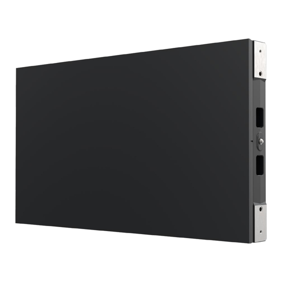
- Page 14 An Amber tile consists of modules, tile frame and power box. Module Power Box Power In Power Out Data Data Magnet Z-gap alignment plate Module Handle Positioning Pin Copyright © 2023 ROE Visual Co., Ltd. All Rights Reserved. 14 / 38...
- Page 15 Basic dimensions of Amber tile. Power box basic dimensions. 34.85 Power box basic information. POWER OUT DATA POWER IN DATA Indicator Module basic dimensions. 13.75 135.00 168.75 275.00 Copyright © 2023 ROE Visual Co., Ltd. All Rights Reserved. 15 / 38...
- Page 16 Amber Series User Manual www.roevisual.com Accessory Information Currently, Amber series support wall mount solution. 3.3.1 Wall Mount System General view of Amber wall mount system. Wall Mounting Frame System Copyright © 2023 ROE Visual Co., Ltd. All Rights Reserved. 16 / 38...
- Page 17 Amber Series User Manual www.roevisual.com Edge Cover (Optional) Copyright © 2023 ROE Visual Co., Ltd. All Rights Reserved. 17 / 38...
- Page 18 Connecting the vertical bars 307003-00034 Spring washer Ф8x14x2 SUS304 with the horizontal bars. Connecting the vertical bars 307003-00035 Flat washerФ8x16x2 SUS304 with the horizontal bars. Copyright © 2023 ROE Visual Co., Ltd. All Rights Reserved. 18 / 38...
- Page 19 Dimensions: 675 x 100 x 20 mm Edge Cover_Side_3H SAP: 316008-00148 Weight: 1580g Dimensions: 1012.5 x 100 x 20 mm Edge Cover Fixed Block SAP: 316008-00135 Weight: 200g Dimensions: φ28X16 mm Copyright © 2023 ROE Visual Co., Ltd. All Rights Reserved. 19 / 38...
- Page 20 Screws for edge cover installation. Fixing the top & bottom Countersunk screw KM4X12 SUS304 307001-00508 edge cover. Fixing all the bridge and Countersunk screw KM3X5 SUS304Φ5.7 307001-00338 connector. Copyright © 2023 ROE Visual Co., Ltd. All Rights Reserved. 20 / 38...
- Page 21 Weight: 0.05 kg RJ45 connector to RJ45 Connector Connect two panels vertically. Data Cable, 0.55m SAP: 208004S0689 Weight: 0.05 kg RJ45 connector to RJ45 Connector Connect two panels horizontally. Copyright © 2023 ROE Visual Co., Ltd. All Rights Reserved. 21 / 38...
- Page 22 Note: The module absorber has a Li-ion rechargeable battery pack inside, so it may not support air transport. The battery pack can be purchased by local web store, please inquire for the compatible battery pack model. Copyright © 2023 ROE Visual Co., Ltd. All Rights Reserved. 22 / 38...
- Page 23 LED modules during transport. 1)Cardboard crate for Amber Tiles Loading Capacity: 10 pcs Tiles (Cabinets with Modules) SAP: 220003S0123 Dimensions: 1102 x 890 x 947 mm Copyright © 2023 ROE Visual Co., Ltd. All Rights Reserved. 23 / 38...
- Page 24 40 pcs 0.52m horizontal bars 206002S0126 Cardboard crate 1220 x 495 x 350 Power and Data cables (Note: An additional inquiry is needed for the packaging information of a specific order.) Copyright © 2023 ROE Visual Co., Ltd. All Rights Reserved. 24 / 38...
- Page 25 Weight Do not underestimate the weight of tiles and frames. Please make sure the floor or truss on which ROE tiles and frames will be installed is capable of handling five times the complete weight of tiles and frames.
- Page 26 Step 2: Remove the component and drill the holes on the wall. Step 3: Level the rectangular component, then fasten it to the wall with HM6X35 bolts & M6 nuts. Copyright © 2023 ROE Visual Co., Ltd. All Rights Reserved. 26 / 38...
- Page 27 The rectangular component is lock by 4 pcs HMX35 bolt and 4 M6 nuts. Step 5: Install the middle horizontal bar to the fixed components with screws (307008-00007). Copyright © 2023 ROE Visual Co., Ltd. All Rights Reserved. 27 / 38...
- Page 28 Step 6: Drilling holes in the wall with a hammer drill, and use HM6X35 bolts & M6 nuts to fix the bars at the locations shown (1~2~3~4). Step 7: Repeat steps 1 ~ 6 until the first row of frames is fully installed. Copyright © 2023 ROE Visual Co., Ltd. All Rights Reserved. 28 / 38...
- Page 29 Connect the Rectangular Component Side with the bottom one and fix the component as in step 3 ~4. Step 9: Repeat the above steps until all wall mounts frame are installed. Copyright © 2023 ROE Visual Co., Ltd. All Rights Reserved. 29 / 38...
- Page 30 After the frame is installed and levelled well. Pre-mount the Amber panels to the frame. There is a mushroom pin at the four corners of the panel. Copyright © 2023 ROE Visual Co., Ltd. All Rights Reserved. 30 / 38...
- Page 31 Mount all the Amber cabinet from left to right, and then install the next row from the bottom to top. This Numerical Order is an 12X12 Screen Example Use the alignment plate to force align the Amber cabinets. Copyright © 2023 ROE Visual Co., Ltd. All Rights Reserved. 31 / 38...
- Page 32 (Note: The screw in Z-direction is only used to lock the cabinet to the wall frame. The Z-gap is adjusted by the screw on the wall frame, and the adjusting range is from -10mm to +10mm.) Copyright © 2023 ROE Visual Co., Ltd. All Rights Reserved. 32 / 38...
- Page 33 Adjust the Z-axis depth if there is a flatness issue from the module level. The adjusting range is from 0 to 2mm. Z-gap alignment plate Copyright © 2023 ROE Visual Co., Ltd. All Rights Reserved. 33 / 38...
- Page 34 How to calculate the power cable capacity Formula: Voltage * Current) / Max. Power Consumption If the voltage is 220V, one power cable can load 12~14 pcs Amber Series tiles. If the voltage is 110V, one power cable can load 6~7 pcs Amber Series tiles.
- Page 35 With different perspective, the mapping direction will be totally reversed. The data cable is limited below 100 m. If the project needs longer control distance, please switch to fiber cables with the fiber adaptor. Copyright © 2023 ROE Visual Co., Ltd. All Rights Reserved. 35 / 38...
- Page 36 Amber Series User Manual www.roevisual.com Control System ROE provides three different control systems: Megapixel VR Helios, Brompton Tessera and ROE Evision. For more information about system operation, please check the corresponding control system user manual. 1. ROE Evision Control System User Manual 2.
- Page 37 After the module is firmly absorbed by the suction pad, pull out the module. Disconnect the safety wire and swap the module. Copyright © 2023 ROE Visual Co., Ltd. All Rights Reserved. 37 / 38...
- Page 38 Corrected Specifications, installation details and Loki 2022.11.04 Control System. Corrected the Service Manual and update Contact V3.1 Information. 2023.03.27 V3.2 Add the threaded holes info of the panel Loki 2023.10.26 Copyright © 2023 ROE Visual Co., Ltd. All Rights Reserved. 38 / 38...
Need help?
Do you have a question about the Amber Series and is the answer not in the manual?
Questions and answers