Table of Contents
Advertisement
Advertisement
Table of Contents

Related Manuals for ROE Diamond 2.6


Summary of Contents for ROE Diamond 2.6
- Page 1 Diamond 2.6 User Manual Version: 2.3 Updated: 2019-04-01...
-
Page 2: Copyright
Standard products refer to products officially launched by ROE. Customized products refer to ROE standard products which are partially or totally designed in line with customers’ requirements and demands. Customized systems refer to products with special systems required by customers. -
Page 3: Table Of Contents
Installation Overview ......................20 Quick-start Guide ......................... 21 Hanging System ......................21 Stacking System ......................23 Ballast Weight Calculation ....................25 Cabling........................... 26 Power Cabling......................... 26 2019-04-04 | Copyright © 2019 ROE Visual Co., Ltd. All Rights Reserved. 3 / 37... - Page 4 Replacing the Power Unit ....................35 11.6 Replacing the Receiving Card ..................36 11.7 Replacing the Tile Handle ....................37 11.8 Replacing the Module Handle ..................37 2019-04-04 | Copyright © 2019 ROE Visual Co., Ltd. All Rights Reserved. 4 / 37...
-
Page 5: Safety
All components should be kept dry, clean, lubricated (only of recommended), coated properly, and otherwise maintained in a manner consistent with the part design. ROE products must be used in a manner consistent with their design and inspected on a routine basis for security, wear, deformation, corrosion and any other circumstances that may affect the loading capacity. -
Page 6: Safety Instructions
(9) Please do not use the product near the sea and/or other places with corrosive environment. (10) The installation must be performed by authorized and qualified technical personnel only. 2019-04-04 | Copyright © 2019 ROE Visual Co., Ltd. All Rights Reserved. 6 / 37... -
Page 7: General Introduction
General Introduction Features The lightweight Diamond 2.6(DM2.6) small-pitch LED tile incorporates the magnesium alloy frame design for an easy-to-assembly solution. It's available in both flat or curved configurations. The DM2.6 is the ideal cost-effective LED display solution for rental, stage and fixed applications. -
Page 8: Specifications
-20 °C to 45 °C / -4 °F to 113 °F Storage Temperature -40 °C to 60 °C / -40 °F to 140 °F Operating / Storage Humidity 10 – 90% RH 2019-04-04 | Copyright © 2019 ROE Visual Co., Ltd. All Rights Reserved. 8 / 37... -
Page 9: Installation Requirements
Weight Do not underestimate the weight of tiles and frames. Please make sure the floor or truss on which ROE tiles and frames will be installed is capable of handling five times the complete weight of tiles and frames. Do not forget to take into consideration the ballast weight required by the stacking system. -
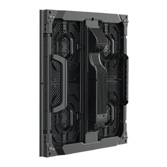
Page 10: Components
A DM2.6 tile consists of modules, tile frame and power box. Tile Frame Module Power Box Magnet Figure 4-1. DM2.6 Components Figure 4-2. DM2.6 Parts Information 2019-04-04 | Copyright © 2019 ROE Visual Co., Ltd. All Rights Reserved. 10 / 37... -
Page 11: Module
A DM2.6 tile consists of 4 pcs modules. Dimensions: 250 x 250 mm Figure 4-3. Module Dimensions Power Box Dimensions: 75 x 390 x 45 mm Figure 4-4. Power Box Dimensions 2019-04-04 | Copyright © 2019 ROE Visual Co., Ltd. All Rights Reserved. 11 / 37... -
Page 12: Accessories
Hanging Bar_Shackle_0.5m SAP: 304010-00275 Weight: 5.2 kg Dimensions: 484 x 80 x60 mm Hanging Bar_Shackle_1.0m SAP: 304010-00276 Weight: 8.6 kg Dimensions: 993 x 80 x 60mm 2019-04-04 | Copyright © 2019 ROE Visual Co., Ltd. All Rights Reserved. 12 / 37... -
Page 13: For Stacking
Dimensions: 1040.5 x 290 x 50 mm Rear Bridge SAP: 206002S0178 Weight: 1.02 kg Dimensions: 232 x 106.5 x 35 mm Rear Bridge Adaptor SAP: 304012-01857 Weight: 0.4 kg 2019-04-04 | Copyright © 2019 ROE Visual Co., Ltd. All Rights Reserved. 13 / 37... -
Page 14: A Complete Stacking System
Note: The stacking system should be used every two-tile wide at least and it’s will be better to be used every one-tile wide when necessary. 2019-04-04 | Copyright © 2019 ROE Visual Co., Ltd. All Rights Reserved. 14 / 37... -
Page 15: Locking Plate & Curving Plate
Press the button to unlock and lock it. The direction is shown on the left. 5.4.3 How to Calculate How Many Locking Plates You Need 2019-03-27 | Copyright © 2019 ROE Visual Co., Ltd. All Rights Reserved. 15 / 36... -
Page 16: Cables
SAP: 208004S0529 Weight: 0.075 kg Neutri_Neutrik Connectors Connect neighboring tiles (vertical). ⑥ Data Cable_0.75m SAP: 208004S0407 Weight: 0.09 kg Neutri_Neutrik Connectors Connect tiles in neighboring columns. 2019-04-04 | Copyright © 2019 ROE Visual Co., Ltd. All Rights Reserved. 16 / 37... - Page 17 5.5.3 Data Cable Plug in the data cable and you feel a “click”. Press the button on the socket and plug the data cable out. 2019-04-04 | Copyright © 2019 ROE Visual Co., Ltd. All Rights Reserved. 17 / 37...
-
Page 18: Package
Capacity: Every flight case can carry 8 pcs tiles. Figure 6-2. DM2.6 Flight Case Note: The left space in the middle of the flight case is designed for cables and / or accessories. 2019-04-04 | Copyright © 2019 ROE Visual Co., Ltd. All Rights Reserved. 18 / 37... - Page 19 DM2.6 User Manual www.roevisual.com 6.1.3 Labels on the Flight Case Warning: Indoor use. Warning: Keep the flight case upwards. Warning: Maximum stack 3 flight cases. Warning: Fragile 2019-04-04 | Copyright © 2019 ROE Visual Co., Ltd. All Rights Reserved. 19 / 37...
-
Page 20: Installation Overview
DM2.6 User Manual www.roevisual.com Installation Overview Video Source 3.Main Data Cable_30m_Neutrik_Neutrik 1.Main Power Cable_10m_Weipu_Neutrik Main Power Cable_10m_Neutrik_Neutrik 4.Data Cable_0.43m_Neutrik_Neutrik 2.Power Cable_0.43m_Neutrik_Neutrik Figure 7-1. DM2.6 Cabling 2019-04-04 | Copyright © 2019 ROE Visual Co., Ltd. All Rights Reserved. 20 / 37... -
Page 21: Quick-Start Guide
(2) Fix more hanging bars and keep them at the same horizontal level through the adjustment wheel. Note: The adjusting range of the adjustment wheel is 13.9mm (vertical) and 157mm (horizontal) respectively. 2019-04-04 | Copyright © 2019 ROE Visual Co., Ltd. All Rights Reserved. 21 / 37... - Page 22 (4) Before installing more panels, fix hanging bars and tiles with locking plates. (5) Before installing more tiles, fix neighboring tiles with locking plates. 2019-04-04 | Copyright © 2019 ROE Visual Co., Ltd. All Rights Reserved. 22 / 37...
-
Page 23: Stacking System
(3) Install the second stacking system, close to the first stacking system and keep them at the same horizontal level through the adjustment wheel. (4) Install tiles on the second stacking system and fix them with 4-way locking plates. 2019-04-04 | Copyright © 2019 ROE Visual Co., Ltd. All Rights Reserved. 23 / 37... - Page 24 (6) Install more tiles and fix them with locking plates. Note: The adjusting range of the feet (stacking bar) is 48mm. 2019-04-04 | Copyright © 2019 ROE Visual Co., Ltd. All Rights Reserved. 24 / 37...
-
Page 25: Ballast Weight Calculation
Base Stabilizer Length (1m) x Ballast Weight (N) = Half of the tile height (m) x Tile Area (㎡) x 125N/㎡ x Safety Factor (1.5) 2019-04-04 | Copyright © 2019 ROE Visual Co., Ltd. All Rights Reserved. 25 / 37... -
Page 26: Cabling
If the voltage is 110V, one power cable can load 7 pcs DM2.6 tiles. Power Source(100~240VAC,50~60HZ) Note: The number in cabling is in line with that of in cables. (See 4.3 Cables.) 2019-04-04 | Copyright © 2019 ROE Visual Co., Ltd. All Rights Reserved. 26 / 37... -
Page 27: Data Cabling
(1) The front view is for the setting in the control system. (2) The cascade control data cables should not be more than 100 meters. When it's over 100 meters, please switch to fiber cables. 2019-04-04 | Copyright © 2019 ROE Visual Co., Ltd. All Rights Reserved. 27 / 37... -
Page 28: Control System
50 Hz 60 Hz 10.1.2 Evision Color Depth 8 bit 10 bit 12 bit Frame Rate 24 Hz 25 Hz 30 Hz 50 Hz 60 Hz 2019-04-04 | Copyright © 2019 ROE Visual Co., Ltd. All Rights Reserved. 28 / 37... -
Page 29: Tile Type
DM2.6 User Manual www.roevisual.com 10.2 Tile Type 10.2.1 Brompton 10.2.2 Evision Note: More information about Brompton & Evision, please refer to the control system user manual. 2019-04-04 | Copyright © 2019 ROE Visual Co., Ltd. All Rights Reserved. 29 / 37... -
Page 30: Service Manual
Step 2: Spray more and keep cleaning until the tile is clean. Note: In terms of the cleaning frequency, it depends on the actual situation. 2019-04-04 | Copyright © 2019 ROE Visual Co., Ltd. All Rights Reserved. 30 / 37... -
Page 31: Installing Tiles
In order to protect LEDs on tile edges from damage, the tile frame should be attracted by magnets first then modules (with LEDs mounted on). 11.2.1 Hanging 2019-04-04 | Copyright © 2019 ROE Visual Co., Ltd. All Rights Reserved. 31 / 37... - Page 32 DM2.6 User Manual www.roevisual.com 11.2.2 Stacking 2019-04-04 | Copyright © 2019 ROE Visual Co., Ltd. All Rights Reserved. 32 / 37...
-
Page 33: Replacing The Module
Note: It’s recommended to push out the module with your thumb at the top left of the module where the magnet locates. Step 2: Take a new module, install it and tighten the safety rope. Note: Please note the direction of the module. 2019-04-04 | Copyright © 2019 ROE Visual Co., Ltd. All Rights Reserved. 33 / 37... -
Page 34: Tools Needed
5.0 ± 0.3 kg / cm Φ4.0 x 25 x 2 # PM4x8mm Module Handle Φ4.0 x 25 x 2 # 4.0 ± 0.5 kg / cm 2019-04-04 | Copyright © 2019 ROE Visual Co., Ltd. All Rights Reserved. 34 / 37... -
Page 35: Replacing The Power Unit
Step 4: Take a new power unit, place and fix it and the electric coupler back with screws. Note: Please note the location of yellow, blue and red terminals. 2019-04-04 | Copyright © 2019 ROE Visual Co., Ltd. All Rights Reserved. 35 / 37... -
Page 36: Replacing The Receiving Card
Step4: Take a new receiving card, place it back and tighten it Step 5: Place back the hub board and tighten it. Step 6: Place back the power box housing and lock four safety locks. 2019-04-04 | Copyright © 2019 ROE Visual Co., Ltd. All Rights Reserved. 36 / 37... -
Page 37: Replacing The Tile Handle
11.8 Replacing the Module Handle Step 1: Unscrew two screws and take down the module handle. Step 2: Take a new module handle, place it back and tighten it. 2019-04-04 | Copyright © 2019 ROE Visual Co., Ltd. All Rights Reserved. 37 / 37...
Need help?
Do you have a question about the Diamond 2.6 and is the answer not in the manual?
Questions and answers