Table of Contents
Advertisement
Quick Links
Advertisement
Table of Contents

Subscribe to Our Youtube Channel
Related Manuals for ROE MC-H


Summary of Contents for ROE MC-H
- Page 1 MC-H User Manual User Manual...
-
Page 2: Table Of Contents
Table of Contents Safety Information Speci cation Connection Accessories Assembly Physical Connection Control System Service and Maintenance Package User Manual... -
Page 3: Safety Information
Read this manual before installing, powering or servicing this product, follow the safety precautions listed below and observe all warnings in this manual and printed on the product. If you have questions about how to operate the tile safely, please contact your ROE supplier. PROTECTION FROM ELECTRIC SHOCK Connect the product to AC mains power within the range 100-240V nominal at 50 or 60 Hz only. - Page 4 Do not modify the product in any way not described in this manual. Install only genuine ROE parts in or on the product unless an alternative is described in this manual. Do not operate the product full load if the ambient temperature of power units (Ta) exceeds 50°C (122° F) or less than -20°C(-4°...
- Page 5 National Electrical Code in the USA, the length of a data cable must not exceed 100 m (332 feet). Avoid exposure of data cables to accidental contact with lightning or power conductors. MC-H LED tiles cannot be hot swapped: Always disconnect the power cord from the control box before connecting or disconnecting the cable string or one of MC-H LED tiles.
-
Page 6: Speci Cation
Specification: MC-H tiles are lightweight and robust outdoor LED display, installation is very easy. They o er wide viewing angles with excellent image integrity and color uniformity, owning the common characteristics of lightweight and rm structure. MC-7H Specification: MC-7H Dimensions: Pixel Pitch 7.5mm... -
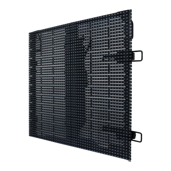
Page 7: Rear Components
MC-12H Specification: MC-12H Dimensions: Pixel Pitch 12.5mm LED Con guration White SMD 3 in 1 Max. Brightness 6,000 nits(NationStar 3535) Transparency Tile Size(W×H×D) 23.6”×23.6”×3.3”/600.0mm×600.0mm×85.0mm Tile Area 0.36m² Pixels/Tile 48×48 Pixels/m² 6400 Viewing Angle 140H/120V degrees Curve Angle -10° / 0° / +10° Weight/Tile 7.5kg/16.5lbs Max. -
Page 8: Connection
1. Neither Hanging bar nor Vertical Interconnect Bolt can load more than 20 tiles of MC-H. Notes: 2. When the Input Voltage is 220V, one Power Cable can load 8 tiles of MC-H; and the Input Voltage is 110V, one Power Cable can load 4 tiles of MC-H. -
Page 9: Accessories
Accessories Name Name Data Cable Evision Name Power Cable SAP No. SAP No. 208004S0242 201000S0007 SAP No. 208001S0754/0611 Dimension Dimension W480×H45×D240mm Dimension 10m/30m Weight Weight 1.4kg Weight 1.8kg/4.6kg 2.3kg Max Length 100m Max Current Name Hanging Bar Name Data Adaptor Name Data Cable SAP No. -
Page 10: Assembly
05 Assembly: Hanging System Hanging bar Dimensions: 612mm Hanging bar components: Adjusting Screw Hanging Clamps Horizental testing liquid column Hole Bolt Horizontal adjusting knob Stacking system assembly exploded diagram Hanging Installation Straight Installation User Manual... - Page 11 Just turn the Adjusting Screw, to make the Clamps close, the Hanging Bar will be fixed on the Truss safely. 2. Connect MC-H tiles with the hanging bar Tiles will be fixed on the hanging bar by Vertical Interconnect Bolt.
-
Page 12: Physical Connection
06 Physical Connection: Straight Installation Horizontal connector operation Picture 1 Picture 2 Picture 3 Picture 4 Picture 5 1. Press the horizontal red button to loosen the handle.(pic1) 2. Pull the handle to turn the connecting bar.(pic2) 3. Connect two tiles and align them.(pic3) 4. -
Page 13: Control System
Control System: The control system of MC-H series consist of receiving card and sending card. Receiving card is integrated with LED tiles. Specifications Working v oltage 100-240V AC Power <20W Working temperature -20°C to 45°C Input port Output ports number... -
Page 14: Service And Maintenance
Figure 1: Maintenance on overall installation Figure 2: Replacement of LED strips 1. Loosen screws and replace the faulty strips. 2. Do repair for the faulty strips. Light status on the rear of MC-H Series Power Data Color of Light... -
Page 15: Package
Package 8 pcs LED tiles per flightcase 1,134.6 691.6 1,112.0 669.0 146.0 820.0 1,112.0 509.0 196.0 720.0 60.0 505.0 21.00 6mmEVA 21.00 9li wood 56.0 56.0 44.0 50.0 390.0 300.0 175.00 56.0 25.00 44.0 100.0 100.0 100.0 100.0 100.0 100.0 100.0 100.0 100.0 Flightcase User Manual... - Page 16 ROE Visual Europe B.V ROE Visual Co., Ltd ROE Visual US, Inc www.roevisual.com www.roevisual.com www.roevisual.com Zernikelaan 2a, Bldg 7, Zhong Yuntai Industrial Park, 2514 N Naomi Street, 9351VA Leek, The Netherlands. Shiyan Town, Shenzhen, China. Burbank, CA, 91504. E: europe@roevisual.com E: roe@roevisual.com...
Need help?
Do you have a question about the MC-H and is the answer not in the manual?
Questions and answers