Advertisement
Quick Links
DALLAIRE
(FP18R model)
US Environmental Protection Agency
phase II certified wood fireplace
compliant with 2020 cord wood
standard
CONTACT LOCAL BUILDING OR FIRE OFFICIALS ABOUT RESTRICTIONS AND INSTALLATION INSPECTION REQUIREMENTS IN
LOCAL AREA.
READ THIS ENTIRE MANUAL BEFORE INSTALLATION AND USE OF THIS WOOD STOVE. FAILURE TO FOLLOW THESE
INSTRUCTIONS COULD RESULT IN PROPERTY DAMAGE, BODILY INJURY OR EVEN DEATH.
READ AND KEEP THIS MANUAL FOR REFERENCE
Printed in Canada
Wood fireplace
Owner's Manual
Part 2 of 2
INSTALLATION AND OPERATION
Only in Canada
REQUIREMENTS
Safety tested according to
ULC S610, and UL
127standards
by an accredited laboratory.
2024-11-25
46400I_A
Advertisement

Related Manuals for Valcourt DALLAIRE


Summary of Contents for Valcourt DALLAIRE
- Page 1 Wood fireplace Owner's Manual Part 2 of 2 INSTALLATION AND OPERATION REQUIREMENTS DALLAIRE (FP18R model) US Environmental Protection Agency Safety tested according to phase II certified wood fireplace ULC S610, and UL compliant with 2020 cord wood 127standards standard by an accredited laboratory.
- Page 2 Dealer: Installer: Phone Number: Serial Numbrer: ONLINE WARRANTY REGISTRATION If the unit requires repairs during the warranty period, proof of purchase must be provided. The purchase invoice must be kept. The date indicated on it establishes the warranty period. If it can not be provided, the warranty period will be determined by the date of manufacture of the product.
- Page 3 Secondary Air Tubes and Baffle Installation .................58 Mobile Home Installation ....................59 Blower replacement ......................60 Glass Door ........................62 Door ..........................63 Removing The Air Channel ....................65 8. Exploded Diagram and Part List ..................66 VALCOURT Limited Lifetime Warranty ..................70 Installation and Operation Manual - Dallaire Page 3...
- Page 4 CERTIFICATION PLATE Page 4 Installation and Operation Manual - Dallaire...
- Page 5 This appliance is officially tested and certified by an independent agency. Tested and certified in compliance with CFR 40 part 60, subpart AAA, section 60.534(a)(1(ii). Carbon monoxide. Installation and Operation Manual - Dallaire Page 5...
- Page 6 CAN/CSA- Z240 MH standard. Tested and certified in compliance with CFR 40 part 60, subpart AAA, section 60.534(a)(1(ii). Page 6 Installation and Operation Manual - Dallaire...
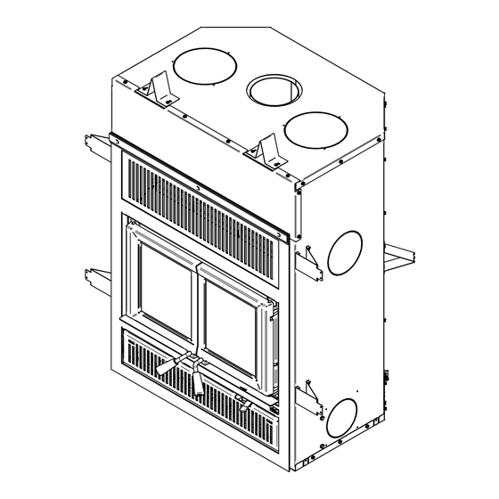
- Page 7 20 3/4" 282mm 527mm 9 3/8" 237mm 33 7/8" 861mm Figure 2: Front View Figure 3: Fornt View - Door opening G : Opening for gravity hot air distribution kit (ø 8"). Installation and Operation Manual - Dallaire Page 7...
- Page 8 F : Opening for forced air distribution kit (ø 6"). A : Opening for fresh air intake (ø 4"). 15 3/4" 400mm 18 3/4" 477mm 17 7/8" 452mm 41 7/8" 1062mm Figure 6: Combustion chamber - Top view Page 8 Installation and Operation Manual - Dallaire...
- Page 9 1/2" 13mm 1" 25mm 16 7/8" 428mm 17" 432mm Figure 7: Left view - Faceplate projection Figure 8: Combustion chamber - Side view Installation and Operation Manual - Dallaire Page 9...
- Page 10 The overall firebox calculation is an approximation and is not intended to be used for loading. This volume includes a buffer zone to allow an easier fuel insertion, prevent ash spillage and allow the air wash to work properly. Page 10 Installation and Operation Manual - Dallaire...
- Page 11 Secondary air tubes and flames Figure 12: Secondary flame Installation and Operation Manual - Dallaire Page 11...
- Page 12 WARNING: DO NOT LEAVE THE FIREPLACE UNATTENDED WHILE A NEW LOAD IS BEING FIRED • HOT. • DO NOT BUILD THE FIRE TOO CLOSE TO THE GLASS. Page 12 Installation and Operation Manual - Dallaire...
- Page 13 2 stacks done first, and, have a rotation of those stack to allow one to dry when you use the dried one. Figure 15: Kindling pieces in a criss-cross stack Installation and Operation Manual - Dallaire Page 13...
- Page 14 The High fire load configuration can be made with 5 medium cordwood pieces of 2.5 in. x 4.5 in (6 cm x 11 cm) approximately. Refer to Page 14 Installation and Operation Manual - Dallaire...
- Page 15 2 other pieces should be added on top of the first 3, stacked in the middle, in an East-West orientation. Figure 20: Coal bed and unburned wood pieces before loading the High-fire load Installation and Operation Manual - Dallaire Page 15...
- Page 16 The Maintenance-fire load configuration is made with 2 larges fuel pieces of 4 in. x 6 in (10 cm x 15 cm) approximately. Figure 22: Maintenance-fire load configuration - Top view Figure 23: Maintenance-fire load configuration - Side view Page 16 Installation and Operation Manual - Dallaire...
- Page 17 15 cm) approximately and 3 medium cordwood pieces of 2.5 in. x 4.5 in (6 cm x 11 cm) approximately. The load configuration is East-West. Figure 26: Low-burn rate load configuration - Top view Figure 27: Low-burn rate load configuration - Side view Installation and Operation Manual - Dallaire Page 17...
- Page 18 (near secondary air tubes) then close the door. Keep the air control fully opened for another 4 minutes minimum and close it partially or completely after that period. Figure 30: Low-fire load in firebox Page 18 Installation and Operation Manual - Dallaire...
- Page 19 AC Triple Wall 6" (15 cm) Metal Fab Temp Guard 1" Solid Pack 6" (15 cm) American Metal AC Triple Wall 6" (15 cm) American Metal AC Triple Wall 6" (15 cm) Installation and Operation Manual - Dallaire Page 19...
- Page 20 Rafter protectors, at the roof level, must be installed with this unit, if the chimney is enclosed at the attic level. Rafter protectors must be made of 22 ga or more galvanized steel and must have at least the dimension presented on the following diagram: Page 20 Installation and Operation Manual - Dallaire...
- Page 21 - Associated components as per these installation instructions. Additional Equipment (optional) • Forced air distribution kit; • Traditional or modern gravity hot air distribution kit; • Fresh air kit; • Fire Screen; • Heat shield for combustible shelf. Installation and Operation Manual - Dallaire Page 21...
- Page 22 To facilitate the transport of the fireplace, handles sold as an option may be used. They are installed on each side of the fireplace. Wearing gloves is strongly recommended when moving the fireplace. Page 22 Installation and Operation Manual - Dallaire...
- Page 23 76mm 45° Fireplace enclosure : 8" 203mm − Back wall : 0" 21" − Sides : 0" 533mm − Floor (underneath the fireplace) : 0" − Chimney : 2" (51 mm) Installation and Operation Manual - Dallaire Page 23...
- Page 24 10 cm). Do not put wood or other material in the area above the fireplace. − Install only the cripple studs needed to support the finishing material and mantle. 41 7/8'' 41 3/4" 1062mm 953mm MIN. MIN. COMBUSTIBLE COMBUSTIBLE VARIABLE Page 24 Installation and Operation Manual - Dallaire...
- Page 25 Cet espace doit rester vide This space must remain empty 80" 2032mm 49 1/8" 1248 mm VARIABLE Installation and Operation Manual - Dallaire Page 25...
- Page 26 (14" [355 mm]) F: Minimum distance between the grill and a non-combustible shelf (Not shown) (15" [381 mm]) G: Distance between the framing and the first stud (3" [76 mm]) Page 26 Installation and Operation Manual - Dallaire...
- Page 27 Smaller dimensions can be used depending on the size and type of duct as well as the configuration of the installation. HVAC duct, as per ULC S110 or UL 181, class 0 or class 1, must withstand temperatures up to 250oF. Installation and Operation Manual - Dallaire Page 27...
- Page 28 A clearance of 80" (2032 mm) between the base of the fireplace and the ceiling must be respected. The minimum floor height under the fireplace should match (or exceed) the height of non-combustible materials used for floor protection. Page 28 Installation and Operation Manual - Dallaire...
- Page 29 A clearance of 80" (2032 mm) (F) between the base of the fireplace and the ceiling must be respected. Installation and Operation Manual - Dallaire Page 29...
- Page 30 Alternatives approved by the local building code may also be used. Do not leave carpets under the floor protection. Page 30 Installation and Operation Manual - Dallaire...
- Page 31 Total R value = .8 + 0.52 = 1.32 Information as reported by manufacturers and other resources Horizontal still air can’t be «stack» to accumulate R-values; each layer must be separated with another non-combustible material. Installation and Operation Manual - Dallaire Page 31...
- Page 32 Unit with Hot air gravity kit 33 1/4" 844mm 80" 2032mm 70" 1777mm 4" 4" 4" 4" 102mm 102mm 102mm 102mm Combustibles materials allowed in this zone Non combustible material only in this zone Page 32 Installation and Operation Manual - Dallaire...
- Page 33 The height (E) should always be 80" (2032 mm) 48" (Canada) 36" (USA) from the base of the fireplace. 1219 mm 914 mm Installation and Operation Manual - Dallaire Page 33...
- Page 34 • WARNING : IF THE CHIMNEY IS INSTALLED IN A CHASE, IT MUST EXCEED THE TOP OF IT BY AT LEAST 3 FEET (92 CM) IF IT’S MADE OF COMBUSTIBLE MATERIALS OR AT LEAST 1.5 FEET (46 CM) WHEN IT IS MADE OF NON-COMBUSTIBLE MATERIALS. Page 34 Installation and Operation Manual - Dallaire...
- Page 35 • If the chimney extends higher than 5 ft. (1.5 m) above its point of contact with the roof, it must be secured using a roof brace. • A rain cap must be installed on top of the chimney. Installation and Operation Manual - Dallaire Page 35...
- Page 36 MUST EXCEED THE TOP OF THE FLASHING CONE BY AT LEAST 12 INCHES (30 CM). THE FLASHING MUST HAVE A MINIMUM HEIGHT OF 6 INCHES (15.25 CM). THE TOP OF THE ENCLOSURE MUST BE MADE OF NON-COMBUSTIBLE MATERIALS. Page 36 Installation and Operation Manual - Dallaire CHEMINÉE: 12" (305mm) MIN. AU-DESSUS DU SOLIN...
- Page 37 • If the male anchor plate nozzle exceeds 2" (51 mm) in length (A), it must be cut above the lifting hooks welded inside the flue outlet so that it is sitting perfectly on the top of the fireplace. Installation and Operation Manual - Dallaire Page 37...
- Page 38 Place the storm collar (F) on the roof flashing and tighten it with the bolt. Seal the joint between the storm collar and the chimney, using silicone sealant. Install the chimney cap (G). Page 38 Installation and Operation Manual - Dallaire...
- Page 39 A maximum of two deviations are permitted in a chimney. A maximum of 6 ft (1,82 m) of unsupported chimney between elbows is permitted. If it is longer than 6 ft (1,82 m), it will need to be supported every 6 ft (1,82 m). Installation and Operation Manual - Dallaire Page 39...
- Page 40 Then, follow the chimney manufacturer’s instructions to connect the extended liner section to the special chimney connector. The liner must extend at least 12" (30 cm) above the masonry chimney. Page 40 Installation and Operation Manual - Dallaire...
- Page 41 Follow the chimney manufacturer’s installation instructions. In cold climate locations, it is recommended to use the insulated wall pass-thru to maintain the home’s thermal barrier. Wall pass-thru Interior wall Exterior wall Installation and Operation Manual - Dallaire Page 41...
- Page 42 (B), there should be a 2" (51 mm) distance between the chimney and combustible materials. It is permitted to offset the chimney when installing the two elbows directly on the anchor plate. Page 42 Installation and Operation Manual - Dallaire...
- Page 43 For example, for the next installation, the chimney cannot be closer to the combustible materials than the value (A). Therefore, the enclosure should be 11 inches (27,94 cm) from the chimney. 2" 5.08cm Installation and Operation Manual - Dallaire Page 43...
- Page 44 96 inches (2,44 m) or more. The offset towards the rear wall can be done 2" (51 mm) between the chimney and the rear wall. It is permitted to offset the chimney when installing the two elbows directly on the anchor plate. 2" 5.08cm Page 44 Installation and Operation Manual - Dallaire...
- Page 45 A faceplate must be installed on this fireplace. See the faceplate installation manual for more details. URBAN STYLE FACEPLATE LOUVERS CLASSIC STYLE FACEPLATE LOUVERS ARABESQUE STYLE FACEPLATE LOUVERS MISSION STYLE FACEPLATE LOUVERS Installation and Operation Manual - Dallaire Page 45...
- Page 46 CROWN STYLE FACEPLATE LOUVERS SPRING INSTALLATION (provided with the product manual kit) Page 46 Installation and Operation Manual - Dallaire...
- Page 47 Note: Only remove the knockout that will be used to connect the fresh air intake assembly. The fresh air intake can be installed in two different locations on the fireplace. On the right side (1) of the fireplace (the most common) or on the left side. Installation and Operation Manual - Dallaire Page 47...
- Page 48 Secure the connection plate (A) with four screws (B) using a star screwdriver (3). Fresh air intake on the right side Adjust the fold of the two closest clips with a flathead screwdriver, just enough to slide a 1/8'' (3,175 mm) plate underneath. Page 48 Installation and Operation Manual - Dallaire...
- Page 49 Install the damper (A) supplied with the product, with the hardware (B) provided in the manual kit. Installation and Operation Manual - Dallaire Page 49...
- Page 50 (9 m). To avoid condensation, it is recommended to use an insulated duct long enough and containing a «P-Trap» loop. This configuration can be done inside the chase, but must at all times maintain clearances to combustibles. MIN 10 pi MAX 3 pi Page 50 Installation and Operation Manual - Dallaire...
- Page 51 − Two 90o elbows (C); − Six steel brackets (D) with six fastening screws (E) and twelve self-tapping screws Parts not included in the kit: − Two 8" rigid ducting (G), 26 ga, galvanized steel. Installation and Operation Manual - Dallaire Page 51...
- Page 52 8 1/4" 1" 208mm 25mm TYP. TYP. 15 1/8" 383mm 5/8" 14mm Dimensions of hot air outlet decorative grille with elbow 10" 254mm TYP. 5/8" 2" 14mm 38mm MIN. MAX. 7/8" 23mm TYP. Page 52 Installation and Operation Manual - Dallaire...
- Page 53 There must be a clearance of at least 2" (51 mm) between the ducts and the firestop. 13" X 13" 330mm X 330mm 12" MIN. 13" X 13" 330mm X 330mm 12" MIN. Installation and Operation Manual - Dallaire Page 53...
- Page 54 (G) (not supplied) into each opening. Position the ducts as shown in the section view below, for optimal heat capture. Screw each duct in place in the brackets (D) with 6 self-drilling screws (F). 2 1/4" 56mm Page 54 Installation and Operation Manual - Dallaire...
- Page 55 However, this appliance has already been tested for emission Installation and Operation Manual - Dallaire Page 55...
- Page 56 Lift the firescreen upwards and push the bottom part towards the fireplace then let the firescreen rest on the bottom of the door opening. Page 56 Installation and Operation Manual - Dallaire...
- Page 57 7.7 Removing the air channel) and then panel brackets (G) and the side refractory remove the floor refractory panels (E) without panels (I). risk of breaking anything. 5/16" Remove the back refractory panel (F). Installation and Operation Manual - Dallaire Page 57...
- Page 58 5. Repeat steps 1 and 2 for the two front tubes. 6. To remove the tubes use the above steps in reverse order. Note that secondary air tubes (A) can be replaced without removing the baffle board (B). Page 58 Installation and Operation Manual - Dallaire...
- Page 59 • CAUTION : THE STRUCTURAL INTEGRITY OF THE MOBILE HOME FLOOR, WALL, CEILING AND ROOF MUST BE MAINTAINED. • IT IS PROHIBITED TO USE THIS WOOD FIREPLACE WITH A FIRE SCREEN IN A MOBILE HOME. Installation and Operation Manual - Dallaire Page 59...
- Page 60 90° to pull out. Unplug the wires and unplug the blower’s Remove the ground (B) from the fireplace. electric wires (P) and (Q). Repeat the steps in reverse order to reinstall the blower. Page 60 Installation and Operation Manual - Dallaire...
- Page 61 Blower Connection The wiring should be done by a qualified electrician. The ground (green or skinned wire) must be attached to the fireplace metal frame. MANUEL AUTO Installation and Operation Manual - Dallaire Page 61...
- Page 62 Peel off more of the backing and rotate the glass. The gasket must not be stretched during installation. Cut the gasket to the required length. Pinch the gasket onto the glass in a U-shape, all around the glass. Page 62 Installation and Operation Manual - Dallaire...
- Page 63 The door seal may be improved with a simple latch mechanism adjustment on the right door: Remove the split pin by pulling and turning it using pliers. Turn the handle one counterclockwise turn to increase pressure. Reinstall the split pin with a small hammer. Installation and Operation Manual - Dallaire Page 63...
- Page 64 24 hours. Location Length Dimension On each door frame 38" (96 cm) Round 5/8" (16 mm) Center door gasket 14" (36 cm) Round 1/4" (6 mm) self-adhesive Page 64 Installation and Operation Manual - Dallaire...
- Page 65 To do this, start by unscrewing the bolt (A) at the front end of the channel, pull the channel forward to unhook it from the bottom. The channel can now be removed from the fireplace. Installation and Operation Manual - Dallaire Page 65...
- Page 66 8. Exploded Diagram and Part List Page 66 Installation and Operation Manual - Dallaire...
- Page 67 BLACK SCREW PAN TORX TYPE F 1/4-20 X 1" PL70483 ASH TRAY 30556 AIR CONTROL FINISHING TIP SE70443 AIR CONTROL ASSEMBLY 30220 FLANGED LOCKNUT 1/4-20 PL73254 AIR HATCH PL63954 4" ADAPTOR PL70463 SIDE STAND-OFF PL70424 SIDE REAR STAND-OFF Installation and Operation Manual - Dallaire Page 67...
- Page 68 PL73262 PILOT PIPE 30060 SCREW 1/4-20 X 1/2'' HEX #3/8 SLOT WASHER TYPE F ZINC PL73271 ATTACHEMENT SUPPORT SE73263 ASS. ADIRON ASHTRAY PL73266 BOTTOM PROTECTION 30084 BOLT 1/4-20 X 1/2'' GRADE 5 Page 68 Installation and Operation Manual - Dallaire...
- Page 69 Item Description Qté PL73259 COLD AIR SYSTEM 30124 MECHANICAL SCREW #8-32 X 5/16'' TRUSS QUADREX #2 ZINC PL73255 HATCH PL73269 FRESH AIR CONNECTION PLATE Installation and Operation Manual - Dallaire Page 69...
- Page 70 *Pictures required **Limited to one replacement Shall your unit or a components be defective, contact immediately your VALCOURT dealer. Prior to your call make sure you have the following information necessary to your warranty claim treatment: Nature of the defect and any relevant information Your name, address and telephone number ▪...
- Page 71 This document is available for free download on the Stove Builder International inc. manufacturer’s website. It is a copyrighted document. 250, De Copenhague street, Resale is strictly prohibited. The manufacturer may update St-Augustin-de-Desmaures (Québec), Canada this document from time to time and cannot be responsible G3A 2H3 for problems, injuries, or damages arising out of the use 1-877-356-6663...
Need help?
Do you have a question about the DALLAIRE and is the answer not in the manual?
Questions and answers