Valcourt FP 10 Installation Instructions Manual
Hide thumbs
Also See for FP 10:
- Installation and operation manual (100 pages) ,
- Installation instructions manual (47 pages) ,
- Quick install/reference manual (2 pages)
Table of Contents
Advertisement
Quick Links
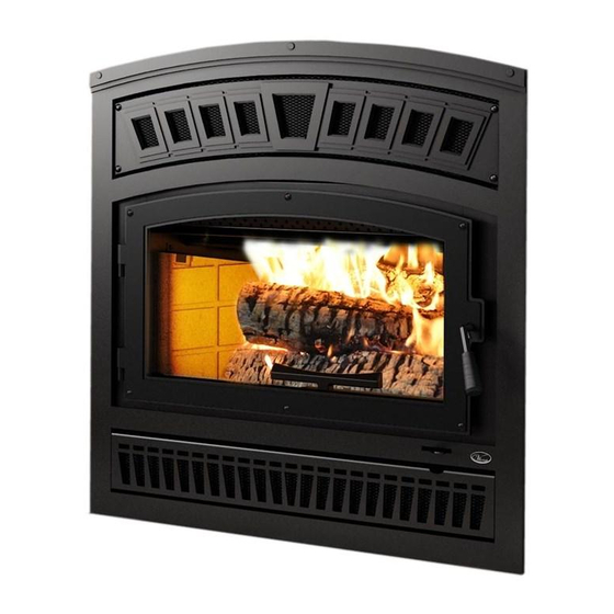
MODEL FP 10 Lafayette
Installation Instructions
This installation manual will help you obtain a safe, efficient, dependable installation for
your fireplace and chimney system. Please read and understand these installation
instructions before beginning your installation.
CAUTION: Do not attempt to modify or alter the construction of the fireplace or its
components. Any modification or alteration of construction may void the warranty,
listings and approvals of this system. In that case, Stove Builder International (SBI) will
not be responsible for damages. Install the fireplace only as described in these
instructions.
PLEASE RETAIN THIS MANUAL FOR FUTURE REFERENCE
Listed to standards ULC-S610, UL-127 and EPA Method 28
250 rue Copenhague, Saint-Augustin-de-Desmaures (Quebec),
This manual is available for free download on the manufacturer's web site. It is a copyrighted
document. Re-sale is strictly prohibited. The manufacturer may update this manual from time to
time and cannot be responsible for problems, injuries, or damages arising out of the use of
information contained in any manual obtained from unauthorized sources.
Printed in Canada
Manufactured by:
Stove Builder International Inc.
Canada, G3A 2H3 Tel.: (418) 878-3040
45436A
30-09-2013
Advertisement
Table of Contents

Related Manuals for Valcourt FP 10


Summary of Contents for Valcourt FP 10
-
Page 1: Installation Instructions
MODEL FP 10 Lafayette Installation Instructions This installation manual will help you obtain a safe, efficient, dependable installation for your fireplace and chimney system. Please read and understand these installation instructions before beginning your installation. CAUTION: Do not attempt to modify or alter the construction of the fireplace or its components. -
Page 2: Table Of Contents
TABLE OF CONTENTS Page MODEL FP 10 Lafayette ......................i Installation Instructions ......................i SAFETY RULES FOR OPERATING YOUR FIREPLACE ........3 THE FIREPLACE ....................5 INTRODUCTION ....................... 5 2.1.1 Parts Required ........................5 ... - Page 3 FRESH AIR KIT ....................... 32 2.6.1 Fresh Air kit Installation ....................32 DOOR OVERLAY INSTALLATION ................34 DOOR ALIGNMENT ....................... 34 FACEPLATE INSTALLATION ..................35 2.10 FIRE SCREEN INSTALLATION (AC01308) ............... 36 ...
-
Page 4: Model Fp 10 Lafayette
SAFETY RULES FOR OPERATING YOUR FIREPLACE Use only a Valcourt glass door, specifically designed for the model FP 10 Lafayette. When cleaning the fireplace, the ashes should be placed in a metal container with a tight fitting lid. The closed container of ashes should be placed on a non-combustible floor or on the ground outside the house, pending final disposal. - Page 5 WARNING: THIS FIREPLACE HAS NOT BEEN TESTED WITH AN UNVENTED OR VENTED GAS LOG SET. TO REDUCE RISK OF FIRE OR INJURY, DO NOT INSTALL AN UNVENTED GAS LOG SET INTO THIS FIREPLACE. WARNING: DO NOT USE MATERIALS OTHER THAN THOSE LISTED IN THE REPLACEMENT PARTS SECTION DURING INSTALLATION AS THEY MAY BE SAFETY HAZARDS AND A FIRE COULD RESULT.
-
Page 6: The Fireplace
2. The FP 10 is not intended for use with a gas log. Failure to follow these instructions will void the certification and the warranty of the fireplace and may result in an unsafe installation. -
Page 7: Operating The Fp 10
OPERATING THE FP 10 2.2.1 Fuel The FP 10 is designed to work best when fuelled with seasoned cordwood. Use solid wood or processed solid fuel fire logs only. Hardwoods are preferred to softwoods since the energy content of wood is relative to its density. Hardwoods will result in a longer burning fire and less frequent refuelling. -
Page 8: First Fires
Your FP 10 fireplace will work best if a thick bed of hot embers is maintained in the bottom of the firebox and a minimum of two large pieces of seasoned fuel are added. Combustion efficiency is largely related to establishing a hot ember bed, and hot firebox temperatures. -
Page 9: Primary Air
2.2.6 Primary Air There is no flue damper in the FP 10. As in common with air tight stoves, the combustion air control sets the flow of air entering the firebox. This allows for a more precise control of the fire. -
Page 10: Combustion Settings
Creosote may accumulate on the glass door. This method of burning should be used only after operating the FP 10 with the air control opened to produce a hot fire for about an hour or at medium pace for at least 2 hours. Slow combustion can be used at night in order to reduce the heat output and to prolong the burn. -
Page 11: Negative Pressure In The House
As the fire burns, air goes up the chimney. This air must be replaced through leakage into the house or through the fresh air kit. When operating the FP 10, open a nearby window temporarily to check if there is adequate air supply replacement. If opening a window solves the problem, the house is under negative pressure. -
Page 12: Maintaining Your Fp 10
F. Do not allow the wood to smoulder or burn without flame, since this will produce excessive creosote in the unit. MAINTAINING YOUR FP 10 2.3.1 Creosote – Formation and need for removal When wood is burned slowly without a flame, it produces tar and other organic vapours which combine with expelled moisture to form creosote. -
Page 13: Dealing With A Chimney Fire
2. Lift the baffle assembly and slide it out of the fireplace. You now have access to the chimney. Figure 2 2.3.4 Dealing with a Chimney Fire Regular chimney maintenance and inspection can prevent chimney fires. If you have a chimney fire, follow these steps: 1. -
Page 14: Disposal Of Ashes
2.3.8 Glass Care – Replacement The glass used in the FP 10 is 5 mm thick of dimension: 5.56" x 13.75" and tested to reach temperatures up to 1400º F. If the glass breaks, it must be replaced with one having the same specification. -
Page 15: Glass Care - Cleaning
Figure 4 2.3.9 Glass Care – Cleaning The FP 10 is designed to keep the glass clean under normal operating conditions. If the FP 10 is operated continuously with the combustion air controls closed, the glass will tend to get dirty unless the fuel, firebox and glass are maintained at higher temperatures. -
Page 16: Gasket Replacement
C. The FP 10 may be installed directly on the floor or on a raised combustible or non combustible base (see figure 5). That base must be at least equal (or exceed) the height of the floor protection. -
Page 17: Heart Extension Requirements
Figure 5. Installation on raised base Figure 6. Ceiling clearance requirements 2.4.2 Heart Extension Requirements The hearth extension floor area must extend at least 18" (40 cm) in front of the hearth and at least 8" (20 cm) on each side of the door opening (see figure 7). The joint between the hearth extension and the fireplace hearth needs to be made of non-combustible material such as sheet metal (not included) as shown on figure 8. -
Page 18: R Calculations
Figure 8 When the fireplace is installed directly on the floor, a noncombustible floor protection in front of the unit must be installed and have an R value insulation equal to or greater than 1.00. The use of an R value is convenient when more than one material is going to be used in the hearth extension to cover the combustible surface. -
Page 19: How To Eliminate The Need Of A R Value
In the case of a known K and thickness of alternative materials to be used in combination, convert all K values to R by dividing the thickness of each material by its K value. Add the R values of your proposed materials as shown in the previous example. Example: K value = 0.75 Thickness = 1... -
Page 20: Framing, Facing, Mantel, And Combustible Shelf
2.4.3 Framing, Facing, Mantel, and Combustible Shelf Framing The construction of the framing, facing, and mantel must be in accordance with the standards and the following illustrations (figures 10 to 14): A. Frame the fireplace using 2" × 3" (5 cm x 8 cm) or heavier lumber. WARNING: COMBUSTIBLE FRAMING MATERIAL CANNOT BE USED IN THE SPACE DIRECTLY ABOVE THE FIREPLACE, EXCEPT FOR THE STUDS ABOVE THE FACING THAT SUPPORT THE FACING MATERIAL AND... - Page 21 Figure 10 Figure 11...
- Page 22 Figure 12 Figure 13...
- Page 23 Figure 14...
-
Page 24: Insulated Chase Construction
INSULATED CHASE CONSTRUCTION Spacers must be installed Spacers must be installed Figure 15 Facing 1. Materials directly in contact with the faceplate of the fireplace, especially the vertical and horizontal surround, must be non-combustible and have the minimal dimensions as shown on figure 16. - Page 25 Figure 16...
- Page 26 Combustible shelf To install any combustible shelf, refer to figure 17 for a safe installation. For example, a shelf with a 6’’ depth (152 mm) must be installed at least 58" (127 cm) above the base of the fireplace. Different shelf dimensions are listed in figure 17 in order to facilitate installation. However, the minimum depth of the shelf is 6"...
- Page 27 Figure 18...
-
Page 28: Blower Connection
2.4.4 Blower connection The fan will come on as soon as the fireplace reaches its minimum start temperature. Have the wiring installed by a qualified electrician. Connect the wires from the power outlet to the terminal block, making sure that the white wire matches the white wire on the terminal. Connect the black wire with the black wire of the terminal block. -
Page 29: Hot Air Ducting Installation
HOT AIR DUCTING INSTALLATION Different hot air ducting systems can be installed with the FP 10: Gravity kit Forced air kit 2.5.1 Gravity Kit The kit includes: 2 x hot air outlets (grilles and frames); 2 x 90 elbows with brackets;... - Page 30 Figure 22 Figure 23 The duct system must be installed respecting the following: 1. Remove the plates closing up the 8" dia. holes on top of the fireplace. Then, cut the insulation in order to obtain two 8" dia. openings. Insert the ducting into each opening and fix it in place using the 6 steel brackets supplied (3 for each duct).
-
Page 31: Central Forced Air Kit
2.5.2 Central Forced Air Kit The knock-outs provided on the back and on the sides of the FP 10 allow the connection of insulated flexible pipe which enables you to heat adjacent rooms up to 50 feet from the fireplace (see figure 26). - Page 32 E) At that point, the flexible pipe can be attached to any air distribution grille. F) Make the electrical connections to the PC Board as explained with the forced air kit owner’s manual. Since the forced air kit requires electricity, make sure that the connections to the fan have been made according to the local codes and comply with their requirements (see instruction provided with the kit).
-
Page 33: Fresh Air Kit
FRESH AIR KIT During operation, the fireplace requires fresh air for combustion and draws air out of the house. It may starve other fuel burning appliances such as gas or oil furnaces. As well, exhaust fans may compete for air, causing negative pressure in the house, resulting in smoke entering the house from the fireplace. - Page 34 pipe clamps. For a better seal, you may also use aluminum tape. Wrap the tape around the joint between the flexible pipe and the air inlets. Carefully push the insulation and plastic cover back over the pipe. Fix the plastic in place using aluminum tape. FRESH AIR INTAKE ALUMINUM OUTSIDE...
-
Page 35: Door Overlay Installation
Figure 33 Figure 32 DOOR OVERLAY INSTALLATION In order to install the door overlay, simply put the overlay on the door frame. Then, pass the 6 bolts through the holes shown in figure 34. Finally, secure the door overlay in place using the 6 nuts. -
Page 36: Faceplate Installation
If the door hinges are misaligned, it will tilt. It is therefore recommended to align them. Once the ideal position has been achieved, lock the hinges in place by tightening the hinges screws. Adjust the pressure on the gasket using the centre adjustment screw located at the bottom of the combustion chamber. -
Page 37: Fire Screen Installation (Ac01308)
2.10 FIRE SCREEN INSTALLATION (AC01308) Open the door. Hold the fire screen by the two handles and bring it close to the door opening. Lean the upper part of the fire screen against the top door opening making sure to insert the top fire screen bracket behind primary... -
Page 38: The Chimney
Installations, which are located on lower floors in the house, such as in a basement, in combination with outside chimney, are especially prone to flow reversal. 2. The FP 10 LAFAYETTE is listed only with chimney systems described in table 1. 3. A chimney venting a fireplace shall not vent any other appliance. - Page 39 Figure 36a Figure 36b...
- Page 40 12. When you build a chase enclosure for chimney sections above the roof, the chimney must extend at least 3 ft. (92 cm) above the chase enclosure and at least 2 ft. (61 cm) higher than any wall, roof or building within 10 ft. (3.1 m) of it. See Figure 36c and 36d to determine the configuration that applies to your roof (flat or sloped roof and the distance between the chimney and the highest point of the roof and/or the nearest chimney).
-
Page 41: Chimney Installation Instructions
CHIMNEY INSTALLATION INSTRUCTIONS 1. Cut and frame the holes in the ceiling, floor and roof where the chimney will pass and install rafter protectors (see figure 37). Use a plumb bob to line up the center of the holes. Make sure that the size of the floor and ceiling holes are in accordance with the chimney manufacturer’s instructions. - Page 42 8. When a ventilated roof flashing is installed, precautions are to be taken not to caulk or seal the ventilating openings. EXAMPLE OF TYPICAL CHIMNEY INSTALLATION Figure 38...
-
Page 43: Offset Chimney Installation
OFFSET CHIMNEY INSTALLATION The minimum system height when using elbows is: Fireplace model FP 10 Chimney model All models Vertical installation 15 ft. (4.6 m) Two (2) elbows 15 ft. (4.6 m) Four (4) elbows 17 ft. (5.2 m) Table 1 After reaching the location requiring the elbow, proceed as follows: 1. - Page 44 Figure 40 Figure 41...
- Page 45 TABLE 2 - LISTED CHIMNEYS FOR YOUR FP 10 CHIMNEY BRAND TYPE INNER DIAMETER MANUFACTURER Selkirk Ultra-Temp (UT) 1” Solid Pack 6" (15 cm) Selkirk Super Pro (SPR) 1” Solid Pack 6" (15 cm) Selkirk Super Vent (JSC) 1” Solid Pack 6"...
- Page 46 Inner diameter 6″ Inner diameter 7″ Reference Parts required. (The numbers in Figure brackets are the parts numbers used 1″ 2″ 1″ 2″ by Security Chimneys) insulation insulation insulation insulation (ASHT+) (S2100+) (ASHT+) (S2100+) Anchor Plate (6SP) Anchor Plate (6XSP) Screws 6″...
-
Page 47: Angled Wall Radiation Shield
ANGLED WALL RADIATION SHIELD When passing through a combustible wall with the chimney at a 30 or 45 angle (30 or 45 in Canada and 30 only in the USA), an angled firestop or wall radiation shield provided by the chimney manufacturer must be installed. -
Page 48: Universal Offset Support
Universal Offset Support This support is used to support the chimney above an offset. When the chimney offset is used to pass through a wall, this support may be used on the wall to support the chimney. For offset support installation, refer to the instructions provided with the support by the chimney manufacturer. -
Page 49: Installation Instructions For Masonry Application
INSTALLATION INSTRUCTIONS FOR MASONRY APPLICATION WARNING: Before starting the installation, the masonry chimney must be inspected by a qualified sweep. The following requirements must be respected: 1. The chimney must be absolutely clear of any soot residue or creosote. Check for cracks, loose or missing bricks that could inhibit correct installation of the liner. -
Page 50: Options
OPTIONS Gravity kit: Part No.: Includes: one deflector, two 90 elbows, and two outlet grilles and frames, . #VA103006 Central forced air kit: Includes: one blower, one 5" flex adapter, 3 pipe clamps, #AC01310 And one control box with heat sensor and PC Board. Rigid spark screen Includes: one rigid spark screen. -
Page 51: Appendix
APPENDIX 5.1. SPECIFICATIONS Weight: 385 lbs Height: 37¼" (95 cm) Width: 36" (91 cm) Depth: 24¾" (63 cm) Maximum recommended heating area: 500 to 2,100 square feet (with forced air kit) Heating capacity* – BTU/hr., EPA test wood: 30,500 Heating capacity* – BTU/hr., seasoned cordwood: 75,000 Optimum efficiency: 77% Test standard –... -
Page 52: Replacement Parts
5.3. REPLACEMENT PARTS Description Part No. Description Part No. Front air tube (1) PL53132 Rear bricks 22138 Air tube (2) – second from front PL53133 Left bricks 22139 Right bricks 22140 Air tube (3) – third from front PL53134 Bottom bricks 22137 Back air tube (4) PL53135... -
Page 53: Valcourt Limited Lifetime Warranty
VALCOURT LIMITED LIFETIME WARRANTY The warranty of the manufacturer extends only to the original consumer purchaser and is not transferable. This warranty covers brand new products only, which have not been altered, modified nor repaired since shipment from factory. Products covered under this warranty must have been manufactured after the revision date indicated below. Proof of purchase (dated bill of sale), model name and serial number must be supplied when making any warranty claim to your VALCOURT dealer.