Table of Contents
Advertisement
Quick Links
Installation and
Operation Manual
FP18 DALLAIRE
(FP18 model)
US Environmental Protection
Safety tested according to ULC
Agency phase II certified wood
S610, UL 127 standards by an
fireplace compliant with 2020
accredited laboratory.
cord wood standard
CONTACT LOCAL BUILDING OR FIRE OFFICIALS ABOUT RESTRICTIONS AND INSTALLATION INSPECTION REQUIREMENTS IN
LOCAL AREA.
READ THIS ENTIRE MANUAL BEFORE INSTALLATION AND USE OF THIS WOOD FIREPLACE. FAILURE TO FOLLOW THESE
INSTRUCTIONS COULD RESULT IN PROPERTY DAMAGE, BODILY INJURY OR EVEN DEATH.
READ AND KEEP THIS MANUAL FOR REFERENCE
Printed in Canada
46307A
2023-03-06
Advertisement
Table of Contents

Related Manuals for Valcourt DALLAIRE FP18


Summary of Contents for Valcourt DALLAIRE FP18
- Page 1 Installation and Operation Manual FP18 DALLAIRE (FP18 model) US Environmental Protection Safety tested according to ULC Agency phase II certified wood S610, UL 127 standards by an fireplace compliant with 2020 accredited laboratory. cord wood standard CONTACT LOCAL BUILDING OR FIRE OFFICIALS ABOUT RESTRICTIONS AND INSTALLATION INSPECTION REQUIREMENTS IN LOCAL AREA.
- Page 3 THANK YOU FOR CHOOSING THIS WOOD FIREPLACE As one of North America’s Contact local building or fire largest and most respected officials about restrictions wood stove and fireplace and installation inspection If this fireplace is not manufacturers, Stove Builder requirements in your local installed properly, International takes pride in the area.
-
Page 4: Table Of Contents
TABLE OF CONTENTS PART A - OPERATION AND MAINTENANCE ................7 1. Safety Information ........................7 2. General Information ........................ 8 2.1 Performances ........................8 2.2 Specifications ......................... 9 2.3 Dimensions ........................10 2.4 EPA Loading ........................13 2.5 Materials........................14 2.6 Zone Heating .........................14 2.7 Emissions and Efficiency ....................15 3. - Page 5 Appendix 6: Refractory Panels Removal .................. 61 Appendix 7: Secondary Air Tubes and Baffle Installation ............62 Appendix 8: Blower Replacement .................... 63 Appendix 9: Exploded Diagram and Parts List ................ 65 Valcourt Limited Lifetime Warranty ................... 68 Dealer: Installer: Phone Number:...
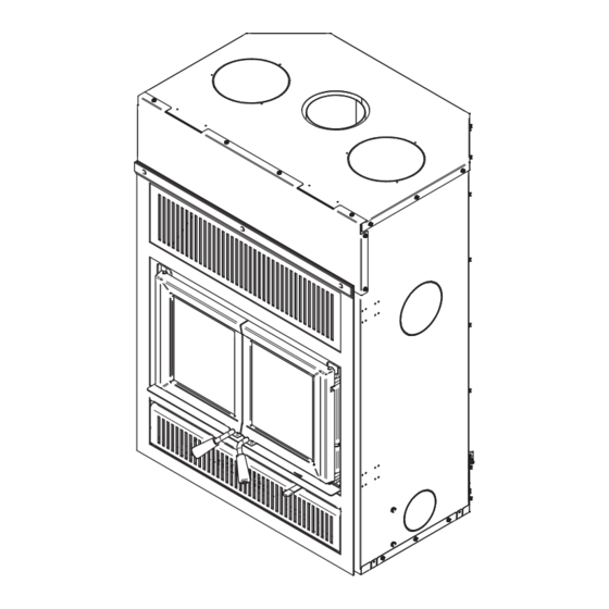
- Page 6 CERTIFICATION PLATE Page 6 Installation and Operation Manual - FP18 Dallaire...
-
Page 7: Part A - Operation And Maintenance
PART A - OPERATION AND MAINTENANCE 1. Safety Information • This fireplace has been tested for use with an open door in conjunction with a firescreen, sold separately. The door may be opened, or firescreen removed only during lighting procedures or reloading. -
Page 8: General Information
2. General Information Performances Values are as measured per test method, except for the recommended heating area, firebox volume, maximum burn time and maximum heat output. Model FP18 Dallaire (FP18) Fuel Type Dry Cordwood Combustion Technology Non-Catalytic 750 to 2,500 ft (70 to 232 m Recommended heating area (sq. -
Page 9: Specifications
Specifications Maximum log length 18 in (457 mm) east-west Flue outlet diameter 6 in (152 mm) Recommended connector pipe diameter 6 in (152 mm) Type of chimney CAN/ULC S629, UL 103 HT (2100 °F) Baffle material C-Cast or equivalent Approved for mobile home installation Type of door Double, glass with cast-iron frame Type of glass... -
Page 10: Dimensions
Dimensions 31 1/8" 790mm 20 7/8" 530mm 10 5/8" 270mm 17" 430mm 6" 152mm Top view 11 1/8" 10 1/4" 282mm 262mm 9 3/8" 20 3/4" 238mm 527mm Front view Front view - Door opening G : Opening for Hot air gravity kit (ø 8"). Page 10 Installation and Operation Manual - FP18 Dallaire... - Page 11 14 3/4" 2 1/2" 376mm 64mm 3 7/8" 100mm 15" 380mm 3 7/8" 24" 100mm 609mm 28 7/8" 15" 734mm 380mm Left side view Right side view 41 3/4" 1060mm 7 7/8" 7 7/8" 200mm 200mm 17 1/2" 445mm Bottom view F : Opening for Hot air gravity kit (ø...
- Page 12 15 3/4" 399mm 18 7/8" 480mm 16 1/4" 414mm Combustion chamber - Top view 1/2" 13mm 1" 25.4mm 16 3/8" 414mm 15 5/8" 396mm Left view - Faceplate projection Combustion chamber - Side view Page 12 Installation and Operation Manual - FP18 Dallaire...
-
Page 13: Epa Loading
EPA Loading The loading methods shown below are those used during emissions certification. Fuel used was beech cordwood and fuel length was 16 ± 1 inches. 2.4.1 Air control The air control is located below the ash shelf on the right. -
Page 14: Materials
Materials The body of this fireplace, which is most of its weight, is carbon steel. Should it ever become necessary many years in the future, almost the entire fireplace can be recycled into new products, thus eliminating the need to mine new materials. The paint coating on the fireplace is very thin. -
Page 15: Emissions And Efficiency
Emissions and Efficiency The low smoke emissions produced by the special features inside this fireplace firebox mean that the household will release up to 90% less smoke into the outside environment than if an older conventional fireplace was used. But there is more to the emission control technologies than protecting the environment. -
Page 16: Log Length
Using softwoods avoids overheating the house, which can be a common problem with wood heating in moderate weather. Harder woods are best for colder winter weather when more heat and longer burn cycles are desirable. Hardwood trees like oak, maple, ash and beech are slower growing and longer lived than softer woods like poplar and birch. -
Page 17: Drying Time
Drying Time Firewood that is not dry enough to burn is the cause of most complaints about wood-burning appliances. Continually burning green or unseasoned wood produces more creosote and involves lack of heat and dirty glass doors. Firewood with a moisture content between 15% and 20% will allow the fireplace to produce its highest possible efficiency. -
Page 18: Operating The Fireplace
4. Operating the Fireplace This wood heater has a manufacturer-set minimum low burn rate that must not be altered. It is against federal regulations to alter this setting or otherwise operate this wood heater in a manner inconsistent with operating instructions in this manual. -
Page 19: Burning Wood Efficiently
5. Burning Wood Efficiently First Use Two things happen when burning the first few fires; the paint cures and the internal components are conditioned. As the paint cures, some of the chemicals vaporize. The vapors are not poisonous, but they smell bad. Fresh paint fumes can also trigger false alarms in smoke detectors. When lighting the heater for the first few times, it may be wise to open doors and windows to ventilate the house. -
Page 20: Combustion Cycles
Use four or five sheets of paper tied together and put them on top and around the kindling. Open the air intake control completely, ignite the paper and close the door. The top down fire method has two advantages over the traditional method: first, the fire does not collapse on itself, and it is not necessary to add wood gradually since the combustion chamber is full before the fire is lit. -
Page 21: Rekindling A Fire
Wood burns best in cycles. A cycle starts when a new load of wood is ignited by hot coals and ends when that load has been consumed down to a bed of charcoal about the same size as it was when the wood was loaded. Trying to produce a steady heat output by placing a single log on the fire at regular intervals is not recommended. -
Page 22: Air Intake Control
The best time to remove ash is in the morning, after an overnight fire when the fireplace is relatively cold, but there is still a little chimney draft to draw the ash dust into the fireplace and prevent going out into the room. Ashes should be placed in a tightly covered metal container. - Page 23 Here are some suggestions for building fires suitable for different heating needs. 5.7.1 Flash Fire To build a small fire that will produce a low heat output, use small pieces of firewood and load them crisscross in the firebox. The pieces should only be 3" (76 mm) to 4" (102 mm) in diameter. After raking the coals, lay two pieces parallel to each other diagonally in the firebox and lay two more across them in the other direction.
-
Page 24: Maintenance
A longer burning time is not necessarily an indication of efficient fireplace operation. It is preferable to build a smaller fire that will provide three or four hours of heating than to fully load the firebox for a much longer burn. Shorter burn cycles make it easier to match the heat output of the fireplace to the heat demand for the space. -
Page 25: Glass Door
Glass Door 6.3.1 Cleaning Under normal conditions, the door glass should stay relatively clear. If the firewood is dry enough and the operating instructions in this manual are followed, a whitish, dusty deposit will form on the inner surface of the glass after a week or so of use. This is normal and can be easily removed when the heater is cold by wiping with a damp cloth or paper towel and then drying. - Page 26 To remove or replace the glass (G): Remove the door (H) and place it face-down on something soft. Remove the glass retainers (E) held in place by the screws (D). Remove the frames (F). Remove the glass. If it is damaged install a new one in place. The replacement glass must have a gasket all around.
-
Page 27: Door
Door In order for the fireplace to burn at its best efficiency, the door must provide a perfect seal with the firebox. Therefore, the gasket should be inspected periodically to check for a good seal. The tightness of the door seal can be verified by closing and latching the door on a strip of paper. -
Page 28: Exhaust System
6.4.2 Gasket Use the correct replacement gasket: (A) for the doors and (B) for the doors junction. Both can be purchased from your retailer. The diameter and density of the gasket is important to getting a good seal. Place the doors face-down on something soft like a cushion of rags or piece of carpet. Remove the old gaskets from the door by pulling and prying it out with an old screw driver. - Page 29 6.5.1 Cleaning frequency It is not possible to predict how much or how quickly creosote will form in the chimney. It is important, therefore, to check the buildup in the chimney monthly until the rate of creosote formation is determined. Even if creosote forms slowly in the system, the chimney should be cleaned and inspected at least once each year.
-
Page 30: Part B - Installation
PART B – INSTALLATION Install the fireplace only as described in these instructions and using only the following fireplace components and chimney components from chimney manufacturers listed in «Table 4 : Approved Chimneys». • Fireplace; • Faceplate; • Insulated chimney made by the manufacturers listed in Table 4, with the corresponding specifications: - Chimney lengths;... -
Page 31: Standards
Standards When installed and operated as described in these instructions, this wood fireplace is suitable for use in residential installations. In Canada, the CSA B365 «Installation Code for Solid Fuel Burning Appliances and Equipment» and the CSA C22.1 «Canadian National Electrical Code» are to be followed in the absence of local code requirements. -
Page 32: Location
Location The best location for the fireplace should consider the location of windows, doors, and circulation in the room. There must be enough space in front of the fireplace for the hearth extension and mantel and on the sides or back for the different heat distribution system, for the fresh air intake and for the chimney. - Page 33 Do not use combustible materials for the frame directly above the fireplace. This area should remain empty to a height of 80" (2.03 m) measured from the base of the fireplace. Build the fireplace frame using vertical studs placed on the sides of the fireplace, from the floor to the ceiling.
- Page 34 8.5.1 Framing with gravity air kit install The framing dimensions are for reference only. Non-combustible Framing touching the grills must be made from non-combustible materials (dark area). Finishing material covering the dark framing must be made from non-combustible materials. See facing section. E: Minimum distance between the grill and the combustible ceiling (8") F: Minimum distance below the grill to non-...
- Page 35 The fireplace must not be in contact with any insulation or loose filling material. Inside Cet espace doit rester vide the chase, around the fireplace, insulation This space must remain empty should be covered with drywall panels or any other finishing material except where non- combustible material is required.
- Page 36 8.5.3 Framing with Fresh Air Intake If a finishing material is installed inside the enclosure, its thickness must be added to the following measurements. A : Fresh air intake duct (Fresh air intake can be installed on the right, left or underneath). B : Distance between framing and side fireplace standoff 12"...
-
Page 37: Hearth Extension Construction
8.5.5 Framing with corner installation Framing configuration should be used as a reference only. If a finishing material is installed inside the enclosure, its thickness must be added to the following measurements. Theses values are minimum measurements and may need to be increased to allow the installation of the fresh air intake, the forced air kit or the type of finishing material used. - Page 38 8.6.2 Option #2 - Raised Base Installation of Less Than 4" When the fireplace is installed on a raised base of Less Than 4" (E), a non- combustible floor protection of at least 16" (A) with an R factor of 1.00 must be installed in front of the fireplace.
- Page 39 8.6.4 Floor Protection R FACTOR OPTION INSTALLATION TYPE REQUIRED 16" 36 ¾" 8" On floor level Yes (1.00) (406 mm) (933 mm) (203 mm) 16" 36 ¾» 8" Raised base of less than 4" Yes (1.00) (406 mm) (933 mm) (203 mm) 16"...
- Page 40 8.6.5 R Factor There are two ways to calculate the R-value of the floor protection. First, by adding the R-values of materials used, or by the conversion if the K factor and thickness of the floor protection are given. To calculate the total R value from R values of the materials used, simply add the R-values of materials. If the result is equal to or greater than the R-value requirements, the combination is acceptable.
-
Page 41: Facing
Facing Non-combustible finishing materials such as brick or ceramic can be glued to the facade of the fireplace. Do not put a seal between the faceplate and the finishing material to facilitate the removal of the faceplate if necessary. Unit without option Unit with Hot air gravity kit 80"... -
Page 42: Shelf Installation
Shelf Installation A non-combustible shelf with a depth of 6" (152 mm) to 12" (305 mm) can be installed at least 48" (1219 mm) from the base of the fireplace. In order to install a combustible shelf, a metal heat shield must be installed 5" below the combustible shelf (C). -
Page 43: Supply Of Combustion Air
Supply of Combustion Air The safest and most reliable supply of combustion air for a fireplace is from the room in which it is installed. Room air is already preheated so it will not chill the fire, and its availability is not affected by wind pressures on the house. - Page 44 • The chimney must have at least one support. The maximum chimney length that should be supported by the fireplace is 9 feet (2.75 m) for 2" Solid Pack chimney (5 cm) and 12 feet (3.7 m) for 1" Solid Pack chimney. •...
- Page 45 • For installations where more than one chimney is located in the same non-chase or within the same area, their terminations must be separated by at least 16" (410 mm) horizontally, and 18" (460 mm) vertically. This separation is to prevent smoke migrating from one chimney to another.
- Page 46 9.3.2 Ceiling Supported Installation A : Anchor plate B: Ceiling support C: Framing opening D: Attic insulation shield E: Roof flashing F: Storm collar G: Chimney cap Cut and frame square openings (C) in the ceiling, floor and roof where the chimney will pass. A 2" clearance must be maintained between the chimney and any combustible materials.
- Page 47 9.3.3 Offset Installation Follow the instructions for a ceiling supported RAIN CAP installation until the first elbow. STORM COLLAR Install and turn the elbow in the right direction. Attach to the chimney using three ½" (12 mm) FLASHING ATTIC metal screws. Install the appropriate number of chimney WALL BAND sections to obtain the necessary deviation.
-
Page 48: Angled Wall Pass-Thru Installation
Position the fireplace in its location. Temporarily install the elbow or chimney section (A) on the top of the fireplace and, using a level, mark with an oval the location where the flue liner will enter the masonry chimney. Mark where the flue will pass through the masonry chimney. - Page 49 9.5.2 Offset Support This support is used above a chimney offset. When the offset of the chimney pass through a wall, this support can be installed on the wall to support the chimney. 9.5.3 Offset chimney installation It is permitted to offset the chimney when installing provided that the following measures are always respected.
-
Page 50: Approved Chimneys
Approved Chimneys Table 4 : Approved Chimneys CHIMNEY MANUFACTURER MODEL TYPE DIAMETER Olympia Chimney Ventis 1" Solid Pack 6" (15 cm) SBI Division Venting SBI Division Venting Nexvent 1" Solid Pack 6" (15 cm) Olympia Chimney Champion Chimney System 1" Solid Pack 6"... - Page 51 Table 5 : LIST OF MANDATORY COMPONENTS CHIMNEY MANDATORY COMPONENTS TYPE/MODEL MANUFACTURER 1" Solid Pack : Ventis, Nexvent, Olympia Chimney / • Ventilated roof flashing. Champion Chimney System, SBI Venting Division Rockford Chimney Systems • Requires insulated attic radiation Security Chimney shield unless chimney is enclosed 2"...
-
Page 52: Appendix 1: Optional Faceplate And Louver Installation
APPENDIx 1: OPTIONAL FACEPLATE AND LOUVER INSTALLATION A faceplate and louvers sold separately must be installed on this fireplace. See the faceplate installation manual for more details. Page 52 Installation and Operation Manual - FP18 Dallaire... -
Page 53: Appendix 2: Optional Fresh Air Intake Installation
APPENDIx 2: OPTIONAL FRESH AIR INTAKE INSTALLATION Follow the instructions below for connecting the fireplace to a fresh air intake: • The insulated flexible pipe (D) should be of sufficient length (at least 10') and of a configuration to prevent condensation. - Page 54 Installation It is strongly recommended to wear gloves to complete the installation. To use the air intake on the right side, remove the knockout by cutting the micro-joints. Cut and remove the insulation and the other knockout inside the fireplace (1). To use the opening under the fireplace, only cut the knockout.
- Page 55 Install the flexible duct (D) on the fresh-air inlet adapter (B) using one hose clamp (C). Fix the other end to the outer wall register (E) using the second hose clamp (C). The outer wall register (E) must be installed outside the house. To properly install the flexible duct, gently remove the insulation and plastic wrap to expose the duct.
-
Page 56: Appendix 3: Optional Traditional Hot Air Gravity Kit Installation
APPENDIx 3: OPTIONAL TRADITIONAL HOT AIR GRAVITY KIT INSTALLATION The kit includes: − 2 hot air outlets (grilles (A) and frames (B)); − 2 90o elbows (C); − 6 steel brackets (D) with fastening screws (E) and self-tapping screws (F) Parts not included in the kit: −... - Page 57 Installation rules and advice • The minimum height of the hot air duct is 68" (1.7 m). It must be measured from the base of the fireplace to the top of the hot air outlets. • Do not connect the hot air ducts to a central heating system. The malfunction of the heating system would overheat the fireplace.
- Page 58 Installation It is strongly recommended to wear gloves to complete the installation. Remove the knockout that close the 8" (20 cm) diameter holes on top of the fireplace. Then cut and remove the insulation and the other set of knockout inside the fireplace. Screw 6 steel brackets (D) with 6 screws (E) onto the top of the fireplace (3 per duct).
-
Page 59: Appendix 4: Optional Forced Air Kit Installation
APPENDIx 4: OPTIONAL FORCED AIR KIT INSTALLATION It is possible to connect a forced air kit on the back or on either side of the FP18 Dallaire. This kit allows distributing heat to another room up to 50 feet (15 m) of the fireplace. The insulated flexible pipe (not included in the kit) must be HVAC type pipe and must comply with ULC S110 and/or UL 181, Class 0 or Class 1 Standards and must withstand temperatures up to 250 °F. -
Page 60: Appendix 5: Optional Firescreen Installation
APPENDIx 5: OPTIONAL FIRESCREEN INSTALLATION A firescreen door can be installed on the fireplace. For more details, refer to the installation manual supplied with the firescreen. Warning: Never leave the fireplace unattended while in use with the firescreen. Open the doors. Hold the firescreen and bring it close to the door opening. -
Page 61: Appendix 6: Refractory Panels Removal
APPENDIx 6: REFRACTORY PANELS REMOVAL Remove the floor refractory panels (E). Using a power driver, remove the refractory panel brackets (G) and the side refractory panels (I). Remove the back refractory panel (F). Installation and Operation Manual - FP18 Dallaire Page 61... -
Page 62: Appendix 7: Secondary Air Tubes And Baffle Installation
APPENDIx 7: SECONDARY AIR TUBES AND BAFFLE INSTALLATION Starting with the rear tube, lean and insert the right end of the secondary air tube into the rear right channel hole. Then lift and insert the left end of the tube into the rear left channel. -
Page 63: Appendix 8: Blower Replacement
APPENDIx 8: BLOWER REPLACEMENT To facilitate the blower replacement, it is recommended to remove the faceplate first. Refer to the faceplate installation manual for more details. Take off the faceplate Cut the ty-rap. Lift the blower (A) located under the firebox towards the back. Turn 90°... - Page 64 Blower Connection The wiring should be done by a qualified electrician. Connect the wires from the power outlet to the terminal block, making sure that the white wire matches the white wire on the terminal. Connect the black wire with the black wire of the terminal block. The ground (green or skinned wire) must be attached to the fireplace metal frame.
-
Page 65: Appendix 9: Exploded Diagram And Parts List
APPENDIx 9: ExPLODED DIAGRAM AND PARTS LIST Installation and Operation Manual - FP18 Dallaire Page 65... - Page 66 IMPORTANT: THIS IS DATED INFORMATION. When requesting service or replacement parts for your unit, please provide the model number and the serial number. We reserve the right to change parts due to technology upgrades or availability. Contact an authorized dealer to obtain any of these parts.
- Page 67 Item Description 44207 DOUBLE CAGE BLOWER 176 CFM (CLASS H) VA1150 THERMODISC F120-10F 44080 RHEOSTAT WITHOUT NUT (MODEL KBMS-13BV) PL70113 TERMINAL COVER 44091 ROCKER SWITCH 2 POSITION MSR-8 44085 RHEOSTAT KNOB 44087 RHEOSTAT NUT 44121 FORCED AIR KIT BLOWER 6'' - 2.4A 44131 SPEED CONTROL (2.5 A) VA4460...
-
Page 68: Valcourt Limited Lifetime Warranty
*Pictures required **Limited to one replacement Shall your unit or a components be defective, contact immediately your VALCOURT dealer. Prior to your call make sure you have the following information necessary to your warranty claim treatment: Nature of the defect and any relevant information Your name, address and telephone number ▪... - Page 70 This document is available for free download on the Stove Builder International inc. manufacturer’s website. It is a copyrighted document. 250, De Copenhague street, Resale is strictly prohibited. The manufacturer may update St-Augustin-de-Desmaures (Québec), Canada this document from time to time and cannot be responsible G3A 2H3 for problems, injuries, or damages arising out of the use 418-908-8002...
Need help?
Do you have a question about the DALLAIRE FP18 and is the answer not in the manual?
Questions and answers