Advertisement
Quick Links
EPS ohne Ghostscript
Connection plan
Motor EZ_AA on SDS5000 Harting special
1 Safety notes
Serious risks to life and limb can occur when connecting and operat-
ing motors! Observe the following operating manuals, the operating
manual of the motor as well as the applicable national, local and sys-
tem-specific regulations.
WARNING!
The motor is powered by high electrical voltage!
Touching live parts is extremely dangerous and potentially fatal!
▪
The electrical connection of the motor may be carried out only
by an electrician.
▪
Before performing the electrical connection, switch off the
power supply of the machine with the main switch and secure
it from being turned on again.
▪
Only connect the motor using power connection cables
recommended by STOBER
▪
Do not open the housing of the power plug connector.
ATTENTION! This connection plan applies only to the motor type
and drive controller type specified in the title! Check whether this
connection plan matches the information on the nameplate of the
motor and drive controller and whether the connection cables corre-
spond to this connection plan. In case of questions, contact STOBER.
ATTENTION! Directly connecting the motor to the power grid will
cause damage to the motor! Only connect the motor to the in-
tended drive controller in accordance with this connection plan.
ATTENTION! Connection cables not coordinated to the motor can
cause damage to the motor or result in non-compliance with the
legal requirements for EMC and thus the voiding of warranty
claims! Use connection cables coordinated to your motor from the
STOBER supply range or, when connecting to a drive controller from
a third-party manufacturer, the corresponding original cables of that
manufacturer.
ATTENTION! Motor components such as encoders or temperature
sensors can be damaged by electrostatic discharge! Do not touch
the contacts of the plug connectors with your fingers.
ATTENTION! The plug connectors can be damaged by improper
handling. Note the following information:
§
Tighten the cap nuts of screw connections by hand (not with a
tool).
§
Turn the plug connector of the motor using the connected mat-
ing connector of the connection cable (not with a tool).
§
Turn the plug connector only within the permitted turning
range.
12/2024
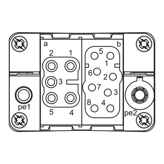
2 Terminal assignment of the power plug
connector
Connection diagram
a
b
5
2
1
1
6
2
3
7
3
8
4
pe1
5
4
pe2
KV = cable gland
3 Terminal assignment of the encoder plug
connector
Connection diagram
Pin
1
3
4
2
2
5
3
1
4
7
8
6
5
6
7
8
KV
KV = cable gland
4 Temperature sensor connection
The type of the temperature sensor is specified on the nameplate of
the motor.
§
PTC thermistor 145 °C
§
Pt1000 temperature sensor
ATTENTION! Incorrect or a lack of monitoring of the temperature
sensor can cause damage to the motor! Always monitor the tem-
perature sensor using devices that will switch the motor off if the
maximum permitted winding temperature is exceeded.
1
Pin
Connection
a1
1U1 (U phase)
a2
1V1 (V phase)
a3
1W1 (W phase)
pe1
PE (grounding
conductor)
b1
1BD1 (brake +)
b2
1BD2 (brake −)
pe2
Inner shield for
1BD1/1BD2
b3
1TP1 (temperature
sensor +)
b4
1TP2 (temperature
sensor -)
pe2
Inner shield for
1TP1/1TP2
KV
Overall shield
Connection
Data +
Data −
Clock −
Clock +
Sense
DGND
UB+
Shield
ID 443453_en.00
Advertisement

Subscribe to Our Youtube Channel
Related Manuals for Stober EZ AA Series


Summary of Contents for Stober EZ AA Series
- Page 1 Overall shield motor and drive controller and whether the connection cables corre- spond to this connection plan. In case of questions, contact STOBER. KV = cable gland ATTENTION! Directly connecting the motor to the power grid will...
- Page 2 Motor EZ_AA on SDS5000 Harting special 5 Holding brake connection The (optional) motor holding brake is connected via the power plug connector. ATTENTION! Connection errors can cause damage to the holding brake! Observe the polarity of the connections and the nominal volt- age of the holding brake.
Need help?
Do you have a question about the EZ AA Series and is the answer not in the manual?
Questions and answers