Table of Contents
Advertisement
Quick Links
GreenPAK Lite Development Board
GreenPAK Lite Development Board provides full set
of programming, emulation, and testing functions for
the GreenPAK devices. Works in pair with the Go
Configure Software Hub. Board functionality is
provided by RX66T series MCU from Renesas.
Specifications
The GreenPAK Lite Development Board R1.1 is
optimized for the following operating conditions:
USB 2.0 specifications to power the board (5.0 V,
■
500 mA)
■
Operating System: Windows 7/8.1/10/11, macOS
(v10.15 or higher), Ubuntu 18.04/20.04/22.04,
Debian 11/Testing
Kit Contents
■
GreenPAK Lite Development Board
USB cable
■
R21UT0253EU0100 Rev.1.00
Oct 20, 2023
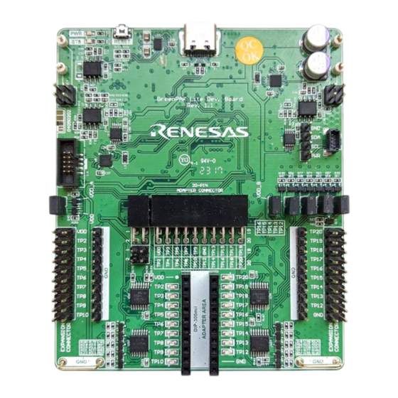
Figure 1. GreenPAK Lite Development Board
Development Board Manual
Features
USB 2.0 board power and communication
■
■
DIP and Socket Adapters support
■
Dual VDD support
Build in current meter for both VDD and VDD2
■
power sources
■
USB-I2C Bridge functionality
18 individually configurable Test Points (TP):
■
●
Onboard LED state indication
●
Pull-up, Pull-down, GND, VDD, Hi-Z, VDD2
●
Programmable software button
■
Configurable dual pin header for user schematic
integration and signal monitoring (Expansion
connector)
4 floating hooks for probe connection
■
Page 1
© 2023 Renesas Electronics
Advertisement
Table of Contents

Related Manuals for Renesas GreenPAK Lite


Summary of Contents for Renesas GreenPAK Lite
-
Page 1: Specifications
Development Board Manual GreenPAK Lite Development Board Features GreenPAK Lite Development Board provides full set of programming, emulation, and testing functions for USB 2.0 board power and communication ■ the GreenPAK devices. Works in pair with the Go ■ DIP and Socket Adapters support Configure Software Hub. -
Page 2: Table Of Contents
GreenPAK Lite Development Board Manual Contents Specifications................................. 1 Kit Contents................................1 Features .................................. 1 Functional Description ..........................4 Working with GreenPAK ..........................7 DIP and Socket Connectors ........................7 2.1.1. DIP and Socket Connectors Specifications ................8 Expansion Connector ..........................8 2.2.1. - Page 3 GreenPAK Lite Development Board Manual Figures Figure 1. GreenPAK Lite Development Board ......................1 Figure 2. GreenPAK Lite Development Board Blocks ....................4 Figure 3. TP3 as Real Time Control Interface ......................5 Figure 4. TP14 as Power Source ..........................5 Figure 5.
-
Page 4: Functional Description
GreenPAK Lite Development Board Manual 1. Functional Description The GreenPAK Lite Development Board R1.1 provides full debugging capabilities for the GreenPAK family ICs. It has the necessary modules and peripherals to power the IC, measure voltages, generate digital signals. Expansion connector was designed to connect the GreenPAK Lite Development Board to external circuits, apply external power, signal sources, and loads. -
Page 5: Tp3 As Real Time Control Interface Figure 4. Tp14 As Power Source
GreenPAK Lite Development Board Manual A set of Test Points provides all interactions between Lite Development Board and GreenPAK integrated circuits. Test Points are configured by the software depending on the actual IC’s manufacturer part number. There are three main options for Test Points – programming interface, real time control interface, and configurable power source. -
Page 6: Table 1. Test Point Functions
GreenPAK Lite Development Board Manual Table 1. Test Point Functions TP1 (VDD) TP10 TP12 TP13 TP14 TP15 TP16 TP17 TP18 TP19 TP20 Test Point with EC connection option is described as E_TPxx in section 2.2 Expansion Connector. R21UT0253EU0100 Rev.1.00 Page 6... -
Page 7: Working With Greenpak
There are five connectors that can establish a connection between GreenPAK and Lite Development Board. DIP and Socket Connectors GreenPAK Lite Development Board works with GreenPAK family products using Socket and DIP Adapters. TP12- TP16 can be configured as VDD2 power sources for dual power devices. Difference between these two connectors is only in form factor. -
Page 8: Dip And Socket Connectors Specifications
GreenPAK Lite Development Board Manual 2.1.1. DIP and Socket Connectors Specifications Table 2 shows onboard power specifications. Table 2. VDD and VDD2 Specifications Parameter Description Unit Output Voltage Range 1.65 ∆V Output Voltage Adjustment Step Maximum Output Current Switch “OFF” Leakage Current Table 3 describes TPs specifications. -
Page 9: Figure 10. Expansion Connector Pinout
GreenPAK Lite Development Board Manual E_VDD E_TP20 E_TP2 E_TP19 E_TP3 E_TP18 E_TP4 E_TP17 E_TP5 E_TP16 E_TP6 E_TP15 E_TP7 E_TP14 E_TP8 E_TP13 E_TP9 E_TP12 E_TP10 Figure 10. Expansion Connector Pinout Figure 11 shows emulation of SLG46826V DIP adapter on the breadboard side. Default and actual device address code is 0001. -
Page 10: Expansion Connector Specifications
GreenPAK Lite Development Board Manual Figure 13. External Oscilloscope Connection Figure 14. Debugging Setup GreenPAK Training Board #2 works with the Lite Development Board through expansion connector. Figure 15 shows correct connection example. Jumper J4 should be removed from Training Board. -
Page 11: Gpsd Connector
GreenPAK Lite Development Board Manual Parameter Description Unit Input Impedance kΩ µF Input Capacitance Table 5 describes E_TPs specifications. All E_TPs can be configured as inputs or outputs. Connection between E_TP and TP, E_VDD and VDD automatically disables during programming and emulation. -
Page 12: Figure 17. Gpsd Connector Pinout
GreenPAK Lite Development Board Manual Figure 17. GPSD Connector Pinout Figure 18 demonstrates emulation of SLG46826V DIP adapter on the breadboard side. Default and actual device address code is 0001. Power for DIP adapter is provided by Lite Development Board. -
Page 13: Gpsd Connector Specifications
GreenPAK Lite Development Board Manual Figure 21. Debugging Setup Figure 20. Training Board #2 Connection 2.3.1. GPSD Connector Specifications Table 6 shows GPSD power specifications. Table 6. PWR Specifications Parameter Description Unit Output Voltage Range ∆V Output Voltage Adjustment Step... -
Page 14: Advanced In-System Programming Connector
GreenPAK Lite Development Board Manual Parameter Description Condition Unit Output High Voltage PWR = 5.5 V Output Low Voltage PWR = 5.5 V 0.08 Output Current Low PWR = 5.5 V Input Voltage Level Range Based on PWR setup -0.2 PWR+0.2... -
Page 15: Additional Features
GreenPAK Lite Development Board Manual 3. Additional Features LED Indication LED state indication option is available for all TPs except TP1 (VDD) and TP10 (GND). Note that input thresholds for LED are the same as in Test Point input specification. If dual VDD GreenPAK is used and VDD2 voltage value is less than VDD1*0.7 –... -
Page 16: Reset Button And Firmware Update
Reset Button and Firmware Update GreenPAK Lite Development Board has a RESET button. It is not necessary to unplug the board from USB for detach action. This can be done with a short time press on RESET button. This button allows to reboot the board or put it into boot mode. -
Page 17: Figure 27. Board Revision Location
GreenPAK Lite Development Board Manual Board Revision Figure 27. Board Revision Location R21UT0253EU0100 Rev.1.00 Page 17 Oct 20, 2023... -
Page 18: Ordering Information
GreenPAK Lite Development Board Manual 4. Ordering Information Part Number Description SLG4DVKLITE GreenPAK Lite Development Board R1.1 R21UT0253EU0100 Rev.1.00 Page 18 Oct 20, 2023... -
Page 19: Revision History
GreenPAK Lite Development Board Manual 5. Revision History Revision Date Description 1.00 Oct 20, 2023 Initial release. R21UT0253EU0100 Rev.1.00 Page 19 Oct 20, 2023...
Need help?
Do you have a question about the GreenPAK Lite and is the answer not in the manual?
Questions and answers