Table of Contents
Advertisement
Quick Links
RL78 Family
RTK7RLG240P00000BJ
RL78/G24 DC/DC LED Control Evaluation Board
User's Manual
All information contained in these materials, including products and product specifications,
represents information on the product at the time of publication and is subject to change by
Renesas Electronics Corp. without notice. Please review the latest information published by
Renesas Electronics Corp. through various means, including the Renesas Electronics Corp.
website (http://www.renesas.com).
Rev.1.00 Sep. 2023
www.renesas.com
Advertisement
Table of Contents

Subscribe to Our Youtube Channel
Related Manuals for Renesas RL78 Series


Summary of Contents for Renesas RL78 Series
- Page 1 All information contained in these materials, including products and product specifications, represents information on the product at the time of publication and is subject to change by Renesas Electronics Corp. without notice. Please review the latest information published by Renesas Electronics Corp. through various means, including the Renesas Electronics Corp.
- Page 2 Renesas Electronics disclaims any and all liability for any damages or losses incurred by you or any third parties arising from the use of any Renesas Electronics product that is inconsistent with any Renesas Electronics data sheet, user’s manual or other Renesas Electronics document.
- Page 3 Unit Products The following usage notes are applicable to all Microprocessing unit and Microcontroller unit products from Renesas. For detailed usage notes on the products covered by this document, refer to the relevant sections of the document as well as any technical updates that have been issued for the products.
- Page 4 How to Use This Manual Purpose and Target Readers This manual is intended for users who want to develop Lighting systems or Digital power supply systems with RL78/G24 microcontrollers. Basic knowledge of electrical circuits, logic circuits, and microcomputers is required to use this manual. This manual is broadly categorized and consists of product overview, specifications, and usage instructions.
- Page 5 Warnings Warning Be careful to avoid burns. The temperature of this part of board increases when AC power is connected. Be careful of LED brightness and the LED On/Off interval. Simulations of strong light may cause symptoms linked to an epileptic condition. Do not use this board for a purpose other than the evaluation of an MCU.
- Page 6 Warning Be careful to avoid burns. Parts of the board, especially the area enclosed by a dotted line, become extremely hot. Do not look directly at LEDs on this board. Doing so may weaken eyesight. Use this board with the LED mounting surface back. Use a specified AC adapter.
-
Page 7: Table Of Contents
Table of Contetns Overview ........................1 Configuration of this product ........................2 Main features of RL78/G24 DC/DC LED Control Evaluation Board ............3 Specification ......................... 4 Spec. of this board ............................. 4 Power input ..............................5 Main components ............................6 Function .............................. -
Page 8: Overview
The customer should also prepare USB cable. By using the RL78/G23 Lighting Communication Master Evaluation Board (RTK7RL23LMP00000B) and a GUI tool (which can be downloaded from the Renesas Electronics’ website), dimming evaluation by DALI-2, DMX512 or infrared data communication protocol is possible. -
Page 9: Configuration Of This Product
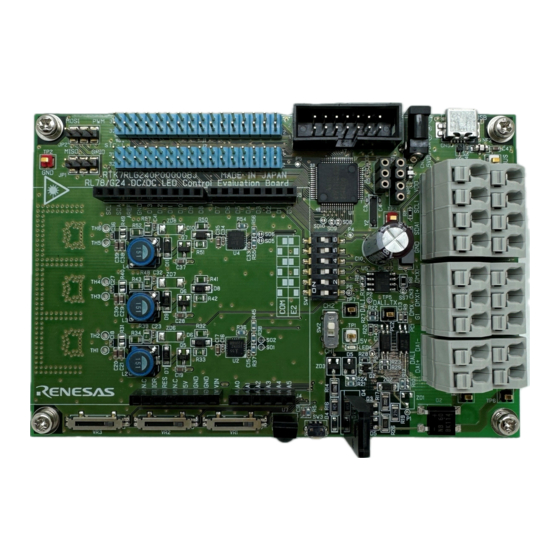
RL78 Family RTK7RLG240P00000BJ RL78/G24 DC/DC LED Control Evaluation Board User’s Manual 1. Overview Configuration of this product This product configures as below : RTK7RLG240P00000BJ(RL78/G24 DC/DC LED Control Evaluation board) High temp. area Fig 2-1 Top High temp. area High temp. area Fig 2-2 Bottom R20UT5371EJ0100 Rev.1.00 Page 2 of 30... -
Page 10: Main Features Of Rl78/G24 Dc/Dc Led Control Evaluation Board
(The E2 emulator lite can also be used for on-chip debugging.) Renesas Flash Programmer (RFP) • Windows based Flash programming software allows the user to select and download application programs to the RL78/G24 DC/DC LED Control Evaluation Board for evaluation purposes via USB. -
Page 11: Specification
RL78 Family RTK7RLG240P00000BJ RL78/G24 DC/DC LED Control Evaluation Board User’s Manual 2. Specification Specification This section describes the specification of this products. Spec. of this board Describes the specification table as below: Table 2-1 Specification Table Item Specification Product Name RTK7RLG240P00000BJ(RL78/G24 DC/DC LED Control Evaluation board)... -
Page 12: Power Input
RL78 Family RTK7RLG240P00000BJ RL78/G24 DC/DC LED Control Evaluation Board User’s Manual 2. Specification Power input Describes specification of power input as blow Table 2-2 Power input specification Power input Voltage Current Power connector AC adapter DC Jack(CN1) EIAJ-2 Table 2-3 Specification of DC Jack Item explanation Manufacture... -
Page 13: Main Components
RL78 Family RTK7RLG240P00000BJ RL78/G24 DC/DC LED Control Evaluation Board User’s Manual 2. Specification Main components The location of main components is shown Fig. 2-1 and Talb 2-4. Also show recommended spec. of cable for DALI communication connector (CN2), DMX512 communication connector(CN3), SMBus/PMBus communication connector(CN4) as Fig.2-2. - Page 14 RL78 Family RTK7RLG240P00000BJ RL78/G24 DC/DC LED Control Evaluation Board User’s Manual 2. Specification Table 2-4 Main parts Reference Name Note Num. MCU(RL78/G24) Connected to XT1 OSC circuit 32.768KHz Xtal oscillator ( subclock ) DC jack +5V Center EIAJ2 USB connecter Mini-B type LED4 Indicator LED...
-
Page 15: Function
RL78 Family RTK7RLG240P00000BJ RL78/G24 DC/DC LED Control Evaluation Board User’s Manual 2. Specification Function This section describes explanation of each function. 2.4.1 Power LED It is equipped with three colors of Power LED: LED1 (red), LED2 (green), and LED3 (blue). The PWM output of the TKBO pin activates the buck converter and controlling each LED. -
Page 16: Dimming Control Interface
RL78 Family RTK7RLG240P00000BJ RL78/G24 DC/DC LED Control Evaluation Board User’s Manual 2. Specification 2.4.2 Dimming control interface This board supported 5 types of dimming control interfaces. This section describes each dimming control interface. DALI-2 protocol communication interface DMX512 protocol communication interface ( also available as RDM-DMX ) SMbus/PMbus protocol communication interface IR remote control interface 3 ch. - Page 17 RL78 Family RTK7RLG240P00000BJ RL78/G24 DC/DC LED Control Evaluation Board User’s Manual 2. Specification 2.4.2.2 DMX512 protocol communication interface It is equipped with connector CN3 for DMX512 protocol communication interface and enables communication with the DMX512 master. In order to enable cascading of connectors, the signals printed on silk are connected as the same signal in the front (first stage) and back (second stage) of the connector.
- Page 18 RL78 Family RTK7RLG240P00000BJ RL78/G24 DC/DC LED Control Evaluation Board User’s Manual 2. Specification 2.4.2.3 SMbus/PMbus protocol communication interface It is equipped with connector CN4 for SMbus/PMbus protocol communication interface and enables communication with the SMbus/PMbus master. In order to enable cascading of connectors, the signals printed on silk are connected as the same signal in the front (first stage) and back (second stage) of the connector.
- Page 19 RL78 Family RTK7RLG240P00000BJ RL78/G24 DC/DC LED Control Evaluation Board User’s Manual 2. Specification 2.4.2.4 IR remote control interface The infrared (IR) detector U7 can be used for performing IR communication between the controller device and the RL78/G24. The controller device can send commands to the RL78/G24 microcontroller using the IR communication protocol.
- Page 20 RL78 Family RTK7RLG240P00000BJ RL78/G24 DC/DC LED Control Evaluation Board User’s Manual 2. Specification 2.4.2.5 Analog volume control interface Three volumes are included for stand-alone evaluation. It can be used as a brightness indication for LED1 (red), LED2 (green), and LED3 (blue) LEDs. For how to operate volumes, see Fig. 2-6. Table 2-13 Volume connected port Port name Direction from MCU...
-
Page 21: On Chip Debug Function
RL78 Family RTK7RLG240P00000BJ RL78/G24 DC/DC LED Control Evaluation Board User’s Manual 2. Specification 2.4.3 On chip debugging function The product supports two on-chip debugging methods: COM Port debugging (Chapter 2.4.3.2) and debugging using the E2 emulator/E2 emulator Lite (Chapter 2.4.3.3). The on-chip debugging method and normal operating mode are switched by switchSW1. - Page 22 RL78 Family RTK7RLG240P00000BJ RL78/G24 DC/DC LED Control Evaluation Board User’s Manual 2. Specification 2.4.3.2 COM Port debugging / Virtual UART communication COM Port debugging is a function that allows you to debugging application software or write a flash program to RL78/G24 devices via USB connection. Connects to a host system via the Mini-B USB connector (CN5).
- Page 23 This function enables on-chip debugging and flash program writing via E2 Emulator / E2 Emulator Lite (manufactured by Renesas Electronics). Connect the user interface cable (14-pin) of the E2 emulator Lite accessory to the debugging connector (J7) of this product and connect to the host system. Using this method, it is possible to perform virtual serial communication and debugging by COM Port at the same time.
-
Page 24: Arduino Uno R3 Interface Connector J3 To J6
RL78 Family RTK7RLG240P00000BJ RL78/G24 DC/DC LED Control Evaluation Board User’s Manual 2. Specification 2.4.4 Arduino UNO R3 Interface connector J3 to J6 J3~J6 is the Arduino UNO R3 interface connector. A 2.54 pitch, straight socket is implemented. For electrical specifications of the available pins, refer to the user's manual for the RL78/G24 device. Fig. -
Page 25: Extended Connector J1 ,J2
RL78 Family RTK7RLG240P00000BJ RL78/G24 DC/DC LED Control Evaluation Board User’s Manual 2. Specification 2.4.5 Extended connector J1 ,J2 J1 and J2 are connectors for external user hardware. A 2.54 pitch, straight header is implemented and connected to the RL78/G24 pin. For electrical specifications of the available pins, refer to the user's manual for the RL78/G24 device. - Page 26 RL78 Family RTK7RLG240P00000BJ RL78/G24 DC/DC LED Control Evaluation Board User’s Manual Table 2-20 Extended J2 pin assignment Extended connector(J2) Pin num Pin name Pin num Pin name P50/INTP1/SI00/RxD0/TOOLRxD/DALIRxD0/SDA00 P50/RxD0/TOOLRxD /TRGIOA/(TRJO0)/(TI03)/(VCOUT3) P51/INTP2/SO00/TxD0/TOOLTxD/DALITxD0/TRGIOB P51/TxD0/TOOLTxD /(VCOUT2) P52_LED2EN P52/(INTP1) P53_LED2PD P53/(INTP2) P54_LED3EN P54/(INTP3) P55_LED3PD P55/(PCLBUZ1)/(SCK00)/(INTP4) P17/CCD01/TI02/TO02/TRDIOA0/TRDCLK/TKBO21 P17/TI02...
-
Page 27: Quick Start
Debugging mode Connect this board with host PC. Starting Start the RFP from the start menu: [Start] - [All Programs] - [Renesas Electronics Utilities] - [Renesas Flash Programmer Vx.xx] Creating project Select [File] - [New project] Fig. 3-1 Create New Project R20UT5371EJ0100 Rev.1.00... - Page 28 RL78 Family RTK7RLG240P00000BJ RL78/G24 DC/DC LED Control Evaluation Board User’s Manual 3. Quick start Open new project window Select Target microcontroller and input project name. Select Tool (COM port), Interface(2 wire UART), COM port num in Tool details. Click connect button Fig.
- Page 29 RL78 Family RTK7RLG240P00000BJ RL78/G24 DC/DC LED Control Evaluation Board User’s Manual 3. Quick start Terminating Select [File] - [Quit] to terminate the RFP. Execute application Set this board to the normal operation mode by applying the following settings. Table 3-2 COM Port Setting for Normal Operation Mode Description...
-
Page 30: Circuit Diagram
RL78 Family RTK7RLG240P00000BJ RL78/G24 DC/DC LED Control Evaluation Board User’s Manual 4. Circuit diagram Circuit diagram R20UT5371EJ0100 Rev.1.00 Page 23 of 30... - Page 31 RL78 Family RTK7RLG240P00000BJ RL78/G24 DC/DC LED Control Evaluation Board User’s Manual 4. Circuit diagram R20UT5371EJ0100 Rev.1.00 Page 24 of 30...
- Page 32 RL78 Family RTK7RLG240P00000BJ RL78/G24 DC/DC LED Control Evaluation Board User’s Manual 4. Circuit diagram R20UT5371EJ0100 Rev.1.00 Page 25 of 30...
- Page 33 RL78 Family RTK7RLG240P00000BJ RL78/G24 DC/DC LED Control Evaluation Board User’s Manual 4. Circuit diagram R20UT5371EJ0100 Rev.1.00 Page 26 of 30...
- Page 34 RL78 Family RTK7RLG240P00000BJ RL78/G24 DC/DC LED Control Evaluation Board User’s Manual 4. Circuit diagram R20UT5371EJ0100 Rev.1.00 Page 27 of 30...
-
Page 35: Parts List
Inductor LQH43MN102K03 Murata Electronics SLF7045T-151MR40- L2,L3,L4 Inductor SLF7045T-151MR40-PF NF2,NF1 NFE31PT222Z1E9L Filter NFE31PT222Z1E9L Murata Electronics ACPL-217-50DE Photo Coupler ACPL-217-50DE Broadcom Limited Renesas PS2801C-1-A/L Photo Coupler PS2801C-1-A/L Electronics P1 to P7 FZT493ATA Transistor FZT493ATA Diodes Incorporated Comchip MMBT2222A-G Transistor MMBT2222A-G Technology STF13N60M2... - Page 36 Through hole Through hole TP8,TP1 HK-5-G-Red Test Pin HK-5-G-Red MAC8 TP3,TP2 HK-5-G-Black Test Pin HK-5-G-Black MAC8 TP4,TP5,TP6,TP7 HK-5-G-White Test Pin HK-5-G-White MAC8 Renesas R7F101GLG2DFB R7F101GLG2DFB Electronics Renesas U2,U4 ISL55110IRZ ISL55110IRZ Electronics Renesas ISL3159EFBZ ISL3159EFBZ Electronics FT232RL FT232RL FTDI American Bright...
- Page 37 RL78 Family RTK7RLG240P00000BJ RL78/G24 DC/DC LED Control Evaluation Board User’s Manual 5. Parts list PSSI2021SAY,115 PSSI2021SAY,115 Nexperia R20UT5371EJ0100 Rev.1.00 Page 30 of 30...
- Page 38 RL78 Family RTK7RLG240P00000BJ Revision History RL78/G24 DC/DC LED Control Evaluation Board User’s manual Rev. Date Description Page Summary 1.00 , Sep., 23 First Edition issued C - 1...
- Page 39 RL78 Family RTK7RLG240P00000BJ RL78/G24 DC/DC LED Control Evaluation Board User’s Manual Publication Date: Rev.1.00 , Sep., 23 Published by: Renesas Electronics Corporation...
- Page 40 RL78 Family R20UT5371EJ0100...
Need help?
Do you have a question about the RL78 Series and is the answer not in the manual?
Questions and answers