Table of Contents
Advertisement
Quick Links
PG-FP5
Flash Memory Programmer
All information contained in these materials, including products and product specifications,
represents information on the product at the time of publication and is subject to change by
Renesas Electronics Corp. without notice. Please review the latest information published by
Renesas Electronics Corp. through various means, including the Renesas Electronics Corp.
website (http://www.renesas.com).
www.renesas.com
User's Manual
Rev.4.00 Jul, 2010
Advertisement
Table of Contents

Subscribe to Our Youtube Channel
Related Manuals for Renesas PG-FP5


Summary of Contents for Renesas PG-FP5
- Page 1 All information contained in these materials, including products and product specifications, represents information on the product at the time of publication and is subject to change by Renesas Electronics Corp. without notice. Please review the latest information published by Renesas Electronics Corp. through various means, including the Renesas Electronics Corp.
- Page 2 Renesas Electronics. Renesas Electronics shall not be in any way liable for any damages or losses incurred by you or third parties arising from the use of any Renesas Electronics product for an application categorized as “Specific”...
- Page 3 European Union only: This equipment (including all accessories) is not intended for household use. After use the equipment cannot be disposed of as household waste. Renesas Electronics Europe GmbH offers to take back the equipment. All you need to do is...
- Page 4 EMC regulation (VCCI, FCC) Please read the following notes about EMC regulation before using. About FCC Note: This equipment has been tested and found to comply with the limits for a Class A digital device, pursuant to part 15 of the FCC Rules. These limits are designed to provide reasonable protection against harmful interference when the equipment is operated in a commercial environment.
- Page 5 General Precautions on Handling This Product 1. Circumstances not covered by product guarantee • If the product was disassembled, altered, or repaired by the customer • If it was dropped, broken, or given another strong shock • Use at overvoltage, use outside guaranteed temperature range, storing outside guaranteed temperature range •...
- Page 6 This manual is intended to give users an understanding of the basic specifications and correct use of the PG-FP5. By using the PG-FP5, programs can be easily erased from or written to the flash memory of a Renesas Electronics on-chip flash memory...
- Page 7 Terminology The meanings of the terms used in this manual are as follows. Term Meaning Abbreviation of the flash memory programmer PG-FP5 Programming GUI Windows application to operate FP5 using programming GUI Target device Renesas Electronics on-chip flash memory microcontroller...
-
Page 8: Table Of Contents
FP5 System Overview ......................13 Operating Environment......................15 1.5.1 Hardware environment........................15 1.5.2 Software environment ........................16 Hardware Specifications......................17 AC Adapters for PG-FP5 ......................18 HCUHEX Files ........................... 19 CHAPTER 2 HARDWARE CONFIGURATION ..................20 Package Contents ........................20 System Configuration ......................20 2.2.1 Host machine ..........................21... - Page 9 4.3.2 [Programmer] menu ........................54 4.3.3 [Device] menu ..........................70 4.3.4 [Help] menu ..........................104 Toolbar............................. 105 Action Log Window ........................ 106 Programming Parameter Window..................107 Status Bar..........................108 Hint Bar............................ 109 CHAPTER 5 EXAMPLE OF OPERATION USING PROGRAMMING GUI ........... 110 CHAPTER 6 USAGE IN STANDALONE MODE ................... 124 Before Starting Standalone Operation .................
- Page 10 8.4.17 selftest command .........................160 8.4.18 sound command...........................161 8.4.19 srec command..........................162 8.4.20 trc command ..........................163 8.4.21 upprm command ..........................164 8.4.22 upset command..........................165 8.4.23 ver command ..........................165 8.4.24 version_up command ........................166 Description of The FP5 Device Commands ................. 168 8.5.1 bln command..........................168 8.5.2 con command..........................169 8.5.3 dcon command..........................169 8.5.4 ep/epv command..........................170...
- Page 11 CHAPTER 12 TROUBLESHOOTING....................200 12.1 Problems During Startup ....................... 200 12.2 Problems During Operation....................201 APPENDIX A MESSAGES........................204 A.1 Message Format........................204 A.2 Error/Warning Dialog Boxes for Programming GUI Operation ........... 205 A.3 Information Dialog Boxes for Programming GUI Operation..........208 A.3 Information Dialog Boxes for Programming GUI Operation..........
-
Page 12: Chapter 1 Overview
PG-FP5 CHAPTER 1 OVERVIEW CHAPTER 1 OVERVIEW The FP5 is a tool that erases, writes and verifies programs on a Renesas Electronics on-chip flash memory microcontroller on the target system or program adapter. Features • Compatible with remote operation for FP5 from an external control device •... -
Page 13: Fp5 System Overview
PG-FP5 CHAPTER 1 OVERVIEW Select the microcontroller to be used in the Each Device Series column and select the device name in the Device Name column; the FP5 parameter file can then be found. FP5 System Overview The FP5 system overview is shown in the following diagrams. - Page 14 PG-FP5 CHAPTER 1 OVERVIEW <Programming GUI operation> The following operations can be performed with the programming GUI. The settings on the host machine are saved in an INI file. • ESF file creation • Downloading program files, PR5 files and ESF files (saved into FP5 internal flash memory) •...
-
Page 15: Operating Environment
• Equipped with RS-232C serial ports (2) Hardware option tools that support FP5 • Target board QB-xxxx-TB (a product of Renesas Electronics, sold separately) • Program adapter FA-xxxx (a product of Naito Densei Machida Mfg. Co., Ltd., sold separately) • IC clip type target cable FA-CLIP (a product of Naito Densei Machida Mfg. Co., Ltd., sold separately) •... -
Page 16: Software Environment
Caution Installation of the latest Service Pack for the OS used is recommended. (2) FP5 parameter file (PR5 file) • Parameter file for the target device used (*.pr5) Reference Download the parameter file from the following Renesas Electronics website. URLs <R> Japanese version: http://www2.renesas.com/micro/ja/ods/ <R>... -
Page 17: Hardware Specifications
PG-FP5 CHAPTER 1 OVERVIEW Hardware Specifications Table 1-1. Hardware Specifications (1/2) Hardware Items Specifications FP5 main Operating power Supplied via AC adapter (15 V) unit supply Temperature: ±0 to +40°C Operating environment Humidity: 10% to 80% RH (no condensation) ccondition Temperature: −15 to +60°C... -
Page 18: Ac Adapters For Pg-Fp5
The specifications of the AC adapter for the PG-FP5 differ depending on the region where the product is being used. Be sure to use the appropriate AC adapter for your region. Note that an AC adapter is not included with the PG-FP5. The appropriate AC adapter must be purchased separately. -
Page 19: Hcuhex Files
Renesas Electronics. HCUHEX files are generated by the HEX Consolidation Utility (HCU), after which they must be verified on a flash memory programmer before being submitted. The PG-FP5 handles HCUHEX files as master data, and can therefore be used to check the written data and the option data settings. For details, see the functional descriptions in this manual. -
Page 20: Chapter 2 Hardware Configuration
Please verify that you have received all the parts listed in the package contents list included with the FP5 package. If any part is missing or seems to be damaged, please contact a Renesas Electronics sales representative or distributor. System Configuration The FP5 system configuration is as shown in the diagram below. -
Page 21: Host Machine
Connect the FP5 power supply connector to the AC adapter included with the FP5. The AC adapter differs depending on the region where the product is being used. For details, see Table 1-2 AC Adapters for PG-FP5 Used in Each Region. -
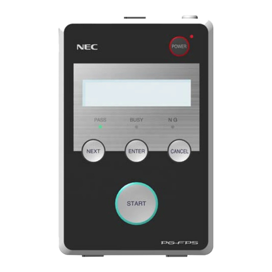
Page 22: Names And Functions On Main Unit
PG-FP5 CHAPTER 2 HARDWARE CONFIGURATION Names and Functions on Main Unit This section describes the names and functions on the FP5 main unit. 2.3.1 FP5 control panel Indicators and buttons are laid out on the FP5 top. Figure 2-2. FP5 Top View <Control Panel>... -
Page 23: Fp5 Connectors
PG-FP5 CHAPTER 2 HARDWARE CONFIGURATION message display functions will change. Refer to 4.3.2 (9) [FP5 Manager] Command and CHAPTER 7 USAGE THE REMOTE CONNECTOR. 2.3.2 FP5 connectors The power supply connector, serial connector and USB connector are laid out on the host interface side. - Page 24 PG-FP5 CHAPTER 2 HARDWARE CONFIGURATION Figure 2-5. FP5 Target Connector Side Target connector Remote connector connector (1) Power supply connector Connect the power supply connector to the AC adapter included with the FP5. For details on the power supply connector specifications, refer to CHAPTER 9 CONNECTORS AND CABLES.
-
Page 25: Chapter 3 Software Installation
• Installation • Uninstallation • Updating programming GUI, firmware and FPGA Obtaining Software Download the programming GUI, USB driver, and FP5 parameter file (PR5 file) from the following Renesas Electronics website. <R> URLs Japanese version: http://www2.renesas.com/micro/ja/ods/ English version (Except for Europe area): http://www2.renesas.com/micro/en/ods/ <R>... -
Page 26: Notes On Installation
(4) The PG-FP5 can only be installed in a folder that is named using ASCII characters. (Note that the 11 characters / * : < > ? | " \ ; , and character strings that begin and end with a space cannot be used.) The PG-FP5 might not operate correctly if installed in a folder that is named using other characters. - Page 27 When the Programming GUI is installed, the USB driver is installed into the driver folder in the Programming GUI installation folder. “C:\Program Files\NEC Electronics Tools\PG-FP5\<Vx.xx>\driver” should usually be specified. <Vx.xx> indicates the version of the programming GUI. Specify the driver folder for the latest programming GUI.
- Page 28 PG-FP5 CHAPTER 3 SOFTWARE INSTALLATION Figure 3-3. Found New Hardware Wizard Window <3> (7) If the following window appears, specify the same folder as specified in (6) for “Copy files from” and then click the OK button. Figure 3-4. Files Needed (8) If the message “Software has not passed Windows Logo testing”...
- Page 29 PG-FP5 CHAPTER 3 SOFTWARE INSTALLATION Figure 3-5. Found New Hardware Wizard Window <4> R20UT0008EJ0400 Rev. 4.00 Page 29 of 240 Jul 15, 2010...
-
Page 30: Uninstallation
PG-FP5 CHAPTER 3 SOFTWARE INSTALLATION Uninstallation This section explains how to uninstall the programming GUI, USB driver, parameter file (PR5 file), customized setup file (ESF file) and setting information file (INI file). The uninstallation order is prescribed. Table 3-2. Uninstallation... -
Page 31: Updating Programming Gui, Firmware And Fpga
<R> English version (Except for Europe area): http://www2.renesas.com/micro/en/ods/ → Click “Version-up Service”. English version (For Europe area): http://www.renesas.eu/update → Section PG-FP5-EE <R> Caution If update of firmware and FPGA is improperly performed, FP5 may no longer operate. Refer to the following procedure or method for updating. -
Page 32: Checking The Current Version
Click “FlashProgrammer” in the Each Development Tool column and then click “FP5_Firmware”. <FPGA> Click “FlashProgrammer” in the Each Development Tool column and then click “FP5_FPGA”. English version (For Europe area): http://www.renesas.eu/update → Section PG-FP5-EE <R> 3.4.2 Installation of programming GUI Run the downloaded executable file (fp5_gui_vxxx_e.exe). -
Page 33: Installation Of Firmware Update
PG-FP5 CHAPTER 3 SOFTWARE INSTALLATION 3.4.3 Installation of firmware update Install the latest firmware by using the latest programming GUI. Decompress the file to any folder. The firmware file “fp5_fw_vxxx.rec” will be decompressed to the selected folder. (“xxx” indicates the firmware version.) (1) Click the [Programmer] menu on the menu bar and select [Update Firmware];... - Page 34 2. When a firmware of FP5 updates from V2.00 to V1.xx, a serial number of FP5 is erased. And, FP5 can't operate in USB1.1. In addition, the other functions don't have any problem. When FP5 revives, consult a Renesas Electronics sales representative or distributor. R20UT0008EJ0400 Rev. 4.00...
- Page 35 PG-FP5 CHAPTER 3 SOFTWARE INSTALLATION (3) Some commands are sent to the FP5 and the update progress status is displayed in the action log window. The message “Firmware Update succeeds”, which indicates normal completion of firmware update, and “Restarting FP5..”, which is equivalent to [RESET] command processing, is automatically performed. The new version can then be checked as “Firmware Version Vx.xx”.
-
Page 36: Installation Of Fpga Update
PG-FP5 CHAPTER 3 SOFTWARE INSTALLATION 3.4.4 Installation of FPGA update Install the latest FPGA by using the latest programming GUI. Decompress the file to any folder. The FPGA file “fp5_fpga_vx.rec” will then be decompressed into the folder, so copy it to any folder. (“x” indicates the FPGA version.) (1) Click the [Programmer] menu on the menu bar and select [Update FPGA];... - Page 37 PG-FP5 CHAPTER 3 SOFTWARE INSTALLATION (2) Click the OK button to continue FPGA update. The [Open FPGA file] dialog box is opened. Figure 3-12. [Open FPGA file] Dialog Box Select the FPGA file “fp5_fpga_vx.rec” and then click the Open button.
- Page 38 PG-FP5 CHAPTER 3 SOFTWARE INSTALLATION (3) Some commands are sent to the FP5 and the update progress status is displayed in the action log window. The message “FPGA Update succeeded” , which indicates normal completion of firmware update, and “FP5 Power will be switched OFF now..”, which is equivalent to processing when the...
- Page 39 PG-FP5 CHAPTER 3 SOFTWARE INSTALLATION (5) Click the [Programmer] menu on the menu bar and select [Setup host connection...]; the [Host Connection] dialog box will then be opened. Select the communication mode used and then click the OK button. Figure 3-14. [Setup host connection] Command Figure 3-15.
- Page 40 PG-FP5 CHAPTER 3 SOFTWARE INSTALLATION (6) Communication with the host machine is established. “FPGA Vx” is displayed in the action log window; thus, the version can be checked. Figure 3-16. Version Confirmation After FPGA Update Is Finished R20UT0008EJ0400 Rev. 4.00...
-
Page 41: Chapter 4 Programming Gui Usage
After the cables are connected, press the POWER button on the FP5. When the FP5 is correctly started, the POWER LED is turned on and “Commands >” is displayed in the message display. If not, the cause may be a defect in the FP5, so consult a Renesas Electronics sales representative or distributor. R20UT0008EJ0400 Rev. 4.00... - Page 42 (3) Startup of programming GUI Click the Start menu, “All Programs”, point to “NEC Electronics Tools”, “Latest Version”, and then select “PG-FP5 Vx.xx” to start the Programming GUI. The valid communication mode is automatically detected in the order of the USB, and then the serial interface.
- Page 43 PG-FP5 CHAPTER 4 PROGRAMMING GUI USAGE Step 3. Clicking Yes will open a dialog box to make a new ESF file. Refer to 4.3.3 (12) (a) <3> New… Button for the steps that follow. Clicking No will open a dialog box to select a previously created ESF file. Refer to 4.3.3 (12) (a) <3> ...
- Page 44 PG-FP5 CHAPTER 4 PROGRAMMING GUI USAGE Figure 4-4. Main Window <1> Menu bar <4> Programmer parameter window <2> Toolbar <3> Action log window <6> Hint bar <5> Status bar The main window consists of the following areas. Name Displayed Items Refer to: <1>...
-
Page 45: Menu Bar
PG-FP5 CHAPTER 4 PROGRAMMING GUI USAGE Menu Bar The menu bar displays the commands that are available for the programming GUI. Some commands may be unavailable when the programming GUI is started for the first time, depending on the parameter file (PR5 file) selected or FP5 Manager setting. - Page 46 PG-FP5 CHAPTER 4 PROGRAMMING GUI USAGE (1) [Hex Editor...] command The [Hex Editor] menu allows you to edit a program file in Intel HEX format or Motorola HEX format. When this command is executed, a program file select dialog box is opened and the file to be edited can be specified.
- Page 47 PG-FP5 CHAPTER 4 PROGRAMMING GUI USAGE Figure 4-7. HEX Editor Main Window Address display area Data display area ASCII display area ID Tag area The displayed file contents can be modified by placing the pointer in the data display area in the HEX Editor main window.
- Page 48 PG-FP5 CHAPTER 4 PROGRAMMING GUI USAGE Figure 4-8. [Save As] Dialog Box of HEX Editor (a) The downloaded PR5 file is for a target device that does not support data flash (b) The downloaded PR5 file is for a target device that supports data flash Besides the file name and folder location, a start address and an end address for the new file can be selected in the [Save As] dialog box.
- Page 49 PG-FP5 CHAPTER 4 PROGRAMMING GUI USAGE Remark For the saved program file contents of the data flash area, refer to Figure B-1 Relationship Between HEX Editor and Saved Program File. (2) [Upload from FP5...] command The [Upload from FP5...] command is used to upload the program file, PR5 file and ESF file saved in a valid programming area.
- Page 50 PG-FP5 CHAPTER 4 PROGRAMMING GUI USAGE <1> [Upload program file from FP5] button The storage location and file name of the program file are specified in the HEX file: box. In order to change the file location or name, click the Save as button and make the changes.
- Page 51 PG-FP5 CHAPTER 4 PROGRAMMING GUI USAGE (3) [Checksum] command The [Checksum] command calculates the checksum of the selected program file downloaded to FP5 and displays the result. When this command is executed, the Checksum dialog box appears. Select the optional calculation method and the target address range, and click the OK button.
- Page 52 PG-FP5 CHAPTER 4 PROGRAMMING GUI USAGE <3> Address range selection Select the range for calculating checksum of the selected program file. If there is no program file data in the specified range, the specified range is filled with FFh for calculation.
- Page 53 PG-FP5 CHAPTER 4 PROGRAMMING GUI USAGE Figure 4-12. Checksum Result <If Downloaded PR5 File Is for Target Device That Supports Data Flash> (4) [Quit] command The [Quit] command terminates the programming GUI. The programming GUI can also be terminated by clicking the ×...
-
Page 54: Programmer] Menu
PG-FP5 CHAPTER 4 PROGRAMMING GUI USAGE 4.3.2 [Programmer] menu Clicking the [Programmer] menu displays the following pull-down menu. This menu includes commands related to FP5 settings. Figure 4-13. [Programmer] Menu (1) [Setup host connection] command Running the [Setup host connection] command opens the [Host Connection] dialog box. - Page 55 PG-FP5 CHAPTER 4 PROGRAMMING GUI USAGE (2) [Logging] command The [Logging] command saves information displayed in the action log window in the log file. When this command is executed, the log file save dialog box appears. Move to an arbitrary folder, select the log file in the [File name] drop-down list, and click the Save button;...
- Page 56 PG-FP5 CHAPTER 4 PROGRAMMING GUI USAGE (3) [Select Programming area] command The FP5 has a 16 MB flash memory area for saving program files. This memory area can be used as four 4 MB programming areas (Area 0 to Area 3) or eight independent 2 MB programming areas (Area 0 to Area 7).
- Page 57 Self-testing takes about three seconds, and the result will be displayed in the action log window and a result dialog box. If the message “Selftest FAILED.” is displayed, the cause may be a defect in the FP5, so consult a Renesas Electronics sales representative or distributor.
- Page 58 PG-FP5 CHAPTER 4 PROGRAMMING GUI USAGE Figure 4-19. Result When Self-Testing Program Has Been Completed Normally <Result Dialog Box> Figure 4-20. Example of Result When Self-Testing Program Has Been Completed Abnormally <Action Log Window> >selftest ***** CAUTION ***** Remove any plugs from Target- and Remote-Connector before starting.
- Page 59 2. When a firmware of FP5 updates from V2.00 to V1.xx, a serial number of FP5 is erased. And, FP5 can't operate in USB1.1. In addition, the other functions don't have any problem. When FP5 revives, consult a Renesas Electronics sales representative or distributor. R20UT0008EJ0400 Rev. 4.00...
- Page 60 PG-FP5 CHAPTER 4 PROGRAMMING GUI USAGE Some commands are sent to the FP5 and the update progress status is displayed in the action log window. The message “Firmware Update succeeds”, which indicates normal completion of firmware update, and “Restarting FP5..”, which is equivalent to [RESET] command processing, is automatically performed. The new version can then be checked as “Firmware Version Vx.xx”.
- Page 61 PG-FP5 CHAPTER 4 PROGRAMMING GUI USAGE (8) [Update FPGA] command The [Update FPGA] command updates the FPGA. Refer to 3.4 Updating Programming GUI, Firmware and FPGA and download the relevant update file before starting update. Executing of this command displays the following dialog box.
- Page 62 PG-FP5 CHAPTER 4 PROGRAMMING GUI USAGE Some commands are sent to the FP5 and the update progress status is displayed in the action log window. The message “FPBGA Upload succeeded.”, which indicates normal completion of firmware update, and “FP5 Power will be switched OFF now..”, which is equivalent to processing when the...
- Page 63 PG-FP5 CHAPTER 4 PROGRAMMING GUI USAGE Figure 4-28. [Setup host connection] Command Figure 4-29. [Host Connection] Dialog Box The main window is opened. “Board H/W V1, FPGA Vx” is displayed in the action log window; thus, the version can be checked.
- Page 64 PG-FP5 CHAPTER 4 PROGRAMMING GUI USAGE Figure 4-30. Version Confirmation After FPGA Update Is Finished R20UT0008EJ0400 Rev. 4.00 Page 64 of 240 Jul 15, 2010...
- Page 65 PG-FP5 CHAPTER 4 PROGRAMMING GUI USAGE (9) [FP5 Manager] command The [FP5 Manager] command sets the FP5 management functions. These functions include the following: The password function, the upload prohibit function, the device setup prohibit function, the bank mode enable function, the simple mode enable function, the checksum comparison function, and the reset terminal property switching function.
- Page 66 PG-FP5 CHAPTER 4 PROGRAMMING GUI USAGE Figure 4-33. Login to FP5 Manager Dialog Box Input the password into the [PASSWORD] box, and then click OK . If the password is correct the dialog box in Figure 4-35 will open. If the password is wrong, then the dialog box in Figure 4-34 will open.
- Page 67 PG-FP5 CHAPTER 4 PROGRAMMING GUI USAGE Figure 4-35. FP5 Manager Dialog Box After making any changes to the settings and clicking OK , the dialog box will close and the settings will be enabled. Clicking Cancel will close the dialog box and discard the changes. The FP5 Manager settings are described below.
- Page 68 PG-FP5 CHAPTER 4 PROGRAMMING GUI USAGE [Enable Bank mode] check box Sets the normal mode or bank mode for the mode of the remote connector. Checking this box will set the bank mode, and not checking it will set the normal mode. If checked, [Enable Simple mode] cannot be checked.
- Page 69 PG-FP5 CHAPTER 4 PROGRAMMING GUI USAGE [Reset option of Run after Disconnect] When the [Run after Disconnect] function in the [Command options] area of the Device setup dialog ¯¯¯¯¯¯ signal after the write command is completed can be [Advanced] tab is enabled, the properties of the RESET set to Pull-up or Hi-Z.
-
Page 70: Device] Menu
PG-FP5 CHAPTER 4 PROGRAMMING GUI USAGE 4.3.3 [Device] menu The following pull-down menu appears by clicking the [Device] menu. This menu includes commands mainly related to programming to the target device, such as erase, write and verify. Figure 4-39. [Device] Menu... - Page 71 PG-FP5 CHAPTER 4 PROGRAMMING GUI USAGE (4) [Verify] command The [Verify] command transmits the memory contents (program files) in the FP5 valid programming area to the target device, verifies the data written to the flash memory in the target device, and receives the result.
- Page 72 PG-FP5 CHAPTER 4 PROGRAMMING GUI USAGE Figure 4-41. Program Data Save Dialog Box <When Write Motorola SREC file Command Is Executed> Clicking the Open button saves the program data into a file and closes the dialog box. Clicking the Cancel button closes the program data save dialog box without saving the program data into a file.
- Page 73 PG-FP5 CHAPTER 4 PROGRAMMING GUI USAGE Figure 4-42. Action Log Window After [Checksum] Command Execution μ <When using 78K0, 78K0S (other than 78K0S/Kx1+ microcontrollers and PD78F9334), 78K0R, or V850> >sum 0x623E PASS > Remark With the 16-bit arithmetic (subtraction) mode, the lower 4 digits of the result from which a value is subtracted from 00h in 1-byte units are displayed.
- Page 74 PG-FP5 CHAPTER 4 PROGRAMMING GUI USAGE Figure 4-44. Action Log Window After [Autoprocedure(E.P.)] Command Execution >ep Blank check Chip: PASS, Erase skipped. Program Chip: 100% PASS Erase, Program operation finished. > (9) [Set Option bytes] command The [Set Option bytes] command specifies the settings for the target device's option byte. When this command is executed, the settings specified in the [Option byte setting] area on the [Advanced] tab of the Device Setup dialog box are applied to the target device.
- Page 75 PG-FP5 CHAPTER 4 PROGRAMMING GUI USAGE (13) [Get Flash options] command The [Get Flash options] command reads the settings for the flash options for the target device and displays the result in the [Flash options] area on the [Advanced] tab in the Device Setup dialog box. When execution of this command is enabled, execute this command before the [Set Security] command, [Set Option bytes] command, or [Set OCD Security ID] command;...
- Page 76 PG-FP5 CHAPTER 4 PROGRAMMING GUI USAGE (14) [Setup] command When the [Setup...] command is executed, the Device Setup dialog box is opened. In this dialog box, select a program file, perform settings in accordance with the user environment for flash memory programming, set command option and option data etc..
- Page 77 PG-FP5 CHAPTER 4 PROGRAMMING GUI USAGE When the OK button (button common to [Target], [Standard] and [Advanced] tabs) is clicked, program areas are cleared and PR5 files, ESF files and program files are downloaded for the FP5. After that, the settings made on the [Target], [Standard] and [Advanced] tabs are saved into an ESF file.
- Page 78 PG-FP5 CHAPTER 4 PROGRAMMING GUI USAGE [Target] tab in Device Setup dialog box Settings related to programming areas, PR5 files, ESF files and program files can be performed on the [Target] tab in the Device Setup dialog box. This tab consists of the following items.
- Page 79 PG-FP5 CHAPTER 4 PROGRAMMING GUI USAGE <1> [Programming Area Setting] area The FP5 has a 16 MB flash memory area for saving program files. This memory area can be used as four 4 MB programming areas (Area 0 to Area 3) or eight independent 2 MB programming areas (Area 0 to Area 7).
- Page 80 PG-FP5 CHAPTER 4 PROGRAMMING GUI USAGE <2> [Target Setting] area In this area, ESF files can be created and selected, and PR5 files and program files can be selected. A warning message will be displayed in the [Information] area if there is a mismatch between PR5 files, ESF files and program files saved in the FP5 and information held in the programming GUI.
- Page 81 PG-FP5 CHAPTER 4 PROGRAMMING GUI USAGE Figure 4-52. ESF File Select Dialog Box New... button Click this button to create a new ESF file. The following dialog box will be displayed. Figure 4-53. New ESF File Creation Dialog Box The PR5 file stored in the FP5_PRJ folder in the programming GUI installation folder is displayed in the [Parameter file:] list.
- Page 82 PG-FP5 CHAPTER 4 PROGRAMMING GUI USAGE Clicking the New... button will open the following dialog box. The PR5 file can be copied to the specified folder of the ESF file with this dialog box. Figure 4-54. [Select parameter files to copy] Dialog Box After selecting the PR5 file, input the new ESF file name and then click the Save button.
- Page 83 PG-FP5 CHAPTER 4 PROGRAMMING GUI USAGE Save As... button Clicking this button opens the dialog box for overwriting the current settings made in the Device Setup dialog box to the existing ESF file, or saving as another file. Specify the file and then click the Open button. Note that the PR5 file is also copied to the destination folder.
- Page 84 Caution Clear this check box when downloading and writing two program files. When a file is downloaded with this check box cleared, the PG-FP5 downloads data 512 bytes at a time without erasing its internal flash memory. Note, however, that the download error “ERROR: NAND flash –...
- Page 85 PG-FP5 CHAPTER 4 PROGRAMMING GUI USAGE Figure 4-57. [Download file] Dialog Box <5> [Information] area and Clear button This area displays a warning message or is used to clear information on PR5 files, ESF files and program files. Figure 4-58. [Information] Area and Clear Button...
- Page 86 PG-FP5 CHAPTER 4 PROGRAMMING GUI USAGE <6> Programming area map area The programming area status can be checked in this area. The FP5 programming areas whose information matches information held in the programming GUI are displayed in light green. In the valid programming area, the names of ESF files, PR5 files and program files, and programming area numbers are displayed in black.
- Page 87 PG-FP5 CHAPTER 4 PROGRAMMING GUI USAGE [Standard] tab in Device Setup dialog box On the [Standard] tab, set the programming environment of the flash memory in the target device. All basic settings to configure the user environment and the target device can be performed. Communication channels, speeds and the operation clock supplied to the target device vary depending on the device, so refer to the user’s...
- Page 88 PG-FP5 CHAPTER 4 PROGRAMMING GUI USAGE <1> [Communication interface to device] area In this area, select the channel and speed for communication between the FP5 and target device. Figure 4-61. [Communication interface to device] Area [Port] list Select the mode of communication between the FP5 and target device. The communication mode is determined...
- Page 89 PG-FP5 CHAPTER 4 PROGRAMMING GUI USAGE Table 4-2. Channels for Communication Between FP5 and Target Device (2/2) Item on Screen Description CSI-Internal-OSC SIO (3-wire clocked communication port) (using internal oscillator) * In the case of 78K0 (All Flash) UART-Ext-FP5CLK UART (asynchronous communication port) (using FP5 clock) *In the case of 78K0 (All Flash)
- Page 90 PG-FP5 CHAPTER 4 PROGRAMMING GUI USAGE • 100k Baud <When Port-ch0, Port-ch1 or Port-ch2 is selected> • 100 Hz • 200 Hz • 300 Hz • 400 Hz • 500 Hz • 600 Hz • 800 Hz • 1000 Hz •...
- Page 91 PG-FP5 CHAPTER 4 PROGRAMMING GUI USAGE [On Target] check box Specify which clock is supplied to the target device: a clock mounted on the target system, or a clock on the FP5 side. If this check box is selected, the clock mounted on the target system will be used. If this check box is cleared, the clock on the FP5 side will be used.
- Page 92 PG-FP5 CHAPTER 4 PROGRAMMING GUI USAGE If [Block] is selected: Specify the block range subject to command processing, using the [Start] and [End] drop-down lists. These lists show the block numbers where flash memory in the target device is configured.
- Page 93 PG-FP5 CHAPTER 4 PROGRAMMING GUI USAGE [Advanced] tab in Device Setup dialog box On the [Advanced] tab, the programming voltage, options added to programming commands, and security settings can be configured. This tab consists of the following items. <1> [Supply voltage] area <2>...
- Page 94 PG-FP5 CHAPTER 4 PROGRAMMING GUI USAGE <1> [Supply voltage] area In this area, specify one (V ) or two (V and V ) voltage levels for target device programming, in accordance with the target device type. Basically, V voltages for target device programming should be supplied from the target system.
- Page 95 PG-FP5 CHAPTER 4 PROGRAMMING GUI USAGE [Vdd monitoring] check box When supplying V from the target system ([On Target] check box: selected), whether to enable the V power supply detection function can be selected with this check box. Select to enable, or clear to disable the function.
- Page 96 PG-FP5 CHAPTER 4 PROGRAMMING GUI USAGE <2> [Command options] area In this area, set options to be added to the [Erase], [Program] and [Autoprocedure(E.P.)] commands. Caution When loading an HCUHEX file, the HCUHEX file is handled as master data. The settings of [Blank check before Erase], [Set Security after Program], [Set Option bytes after Program], and [Set OCD Security ID after Program] therefore cannot be changed.
- Page 97 PG-FP5 CHAPTER 4 PROGRAMMING GUI USAGE voltage] area is selected. If selected, the written program can be automatically executed after each command is finished. [Enable target Reset] check box ¯¯¯¯¯¯ terminal will change to the input mode (Hi-Z). Immediately after execution When this box is checked, the RESET ¯¯¯¯¯¯...
- Page 98 PG-FP5 CHAPTER 4 PROGRAMMING GUI USAGE <3> [Flash options] area Setting of the Set Security command options (security flag settings, block protection settings, reset vector handling function setting, on-chip debug security ID setting, and option byte setting) can performed in this area.
- Page 99 PG-FP5 CHAPTER 4 PROGRAMMING GUI USAGE <4> [Set Security command options] area The security flag settings block protection settings, and reset vector handling function setting can be set in this area. When the [Set Security] command is executed, the settings in this area will be reflected in the target device.
- Page 100 PG-FP5 CHAPTER 4 PROGRAMMING GUI USAGE [Disable Chip Erase] check box If the [Set Security] command is executed with this check box selected, the [Erase] command will be disabled for the entire area of the flash memory in the target device. When this check box is selected, the following dialog box appears.
- Page 101 PG-FP5 CHAPTER 4 PROGRAMMING GUI USAGE Figure 4-72. [Disable Boot block cluster reprogramming] Warning Dialog Box Clicking the OK button determines the selection of the [Disable Boot block cluster reprogramming] check box. Clicking the Cancel button cancels the selection of the [Disable Boot block cluster reprogramming] check box.
- Page 102 PG-FP5 CHAPTER 4 PROGRAMMING GUI USAGE <6> [Block protection settings] area In this area, block settings when the [Disable Boot block cluster reprogramming] check box is selected and block settings for the flash shield window function can be performed. Figure 4-73. [Block protection settings] Area [Boot Block end] drop-down list Select a block number from this list if the [Disable Boot block cluster reprogramming] check box is selected.
- Page 103 PG-FP5 CHAPTER 4 PROGRAMMING GUI USAGE <8> [OCD security ID setting] area The OCD security ID can be set in this area. When the [Set OCD Securitry ID] command is executed, the settings in this area will be reflected in the target device.
-
Page 104: Help] Menu
PG-FP5 CHAPTER 4 PROGRAMMING GUI USAGE 4.3.4 [Help] menu Clicking the [Help] menu displays the following pull-down menu. Figure 4-77. [Help] Menu (1) [Help Topics] command The [Help Topics] command opens the FP5 help file. (2) [About FP5] command This command opens the following dialog box and shows the versions of the programming GUI. -
Page 105: Toolbar
PG-FP5 CHAPTER 4 PROGRAMMING GUI USAGE Toolbar The commands frequently used with the programming GUI are displayed as buttons on the toolbar. A command can be executed just by clicking the relevant button. Some commands may be unavailable depending on the PR5 file selected, or when the programming GUI is started for the first time. -
Page 106: Action Log Window
PG-FP5 CHAPTER 4 PROGRAMMING GUI USAGE Action Log Window This window displays the log of programming GUI actions. Figure 4-79. Action Log Window R20UT0008EJ0400 Rev. 4.00 Page 106 of 240 Jul 15, 2010... -
Page 107: Programming Parameter Window
PG-FP5 CHAPTER 4 PROGRAMMING GUI USAGE Programming Parameter Window This window displays the programming parameter settings. Figure 4-80. Programming Parameter Window [Programmer] area Displays information such as the programming GUI version, FP5 firmware version, valid programming area number, and FP5 mode. -
Page 108: Status Bar
PG-FP5 CHAPTER 4 PROGRAMMING GUI USAGE [File checksum] area Displays the checksum result for execution of the [Checksum...] command in the [File] menu. [Target device] area Displays information of the settings on the [Standard] tab in the Device Setup dialog box. This area is updated after the OK button in the Device Setup dialog box is clicked and files are downloaded. -
Page 109: Hint Bar
PG-FP5 CHAPTER 4 PROGRAMMING GUI USAGE Hint Bar By pointing to a command on the menu bar or a button with the pointer, the hint for the command or button is displayed on the hint bar. Figure 4-82. Hint Bar R20UT0008EJ0400 Rev. -
Page 110: Chapter 5 Example Of Operation Using Programming Gui
PG-FP5 CHAPTER 5 EXAMPLE OF OPERATION USING PROGRAMMING GUI CHAPTER 5 EXAMPLE OF OPERATION USING PROGRAMMING GUI This chapter explains a series of basic FP5 operations using the programming GUI, taking a case where the μ PD78F1166 is used as the target device as an example. This chapter covers how to start the system, execute the [Autoprocedure(E.P.)] command and program the target device. - Page 111 FP5 is ready for operation. If not, the cause may be a defect in the FP5, so consult a Renesas Electronics sales representative or distributor. <4> Refer to CHAPTER 3 SOFTWARE INSTALLATION and install the USB driver (in case Found New Hardware Wizard is started by Plug and Play).
- Page 112 PG-FP5 CHAPTER 5 EXAMPLE OF OPERATION USING PROGRAMMING GUI <2> The communication mode can also be selected by cancelling this operation with the Cancel button and selecting the [Setup host connection] command in the [Programmer] menu. Figure 5-2. [Setup host connection] Command <3>...
- Page 113 PG-FP5 CHAPTER 5 EXAMPLE OF OPERATION USING PROGRAMMING GUI The following dialog box will be displayed. Click Yes or No . Clicking Yes will open a dialog box to make a new ESF file. Refer to 4.3.3 (12) (a) <3> New… Button for the steps that follow.
- Page 114 PG-FP5 CHAPTER 5 EXAMPLE OF OPERATION USING PROGRAMMING GUI Next, the device setup dialog box that is opened when [Device] menu -> [Setup...] command is executed will be opened, so make the settings. Figure 5-5. Main Window R20UT0008EJ0400 Rev. 4.00...
- Page 115 PG-FP5 CHAPTER 5 EXAMPLE OF OPERATION USING PROGRAMMING GUI (6) Setting of programming environment <1> Execute the [Setup...] command in the [Device] menu in the main window. Figure 5-6. [Setup] Command Toolbar: <2> The Device Setup dialog box ([Target] tab) is opened.
- Page 116 PG-FP5 CHAPTER 5 EXAMPLE OF OPERATION USING PROGRAMMING GUI μ <4> Click the New... button to create a new ESF file for the PD78F1166. Figure 5-9. Creation of New ESF File <5> Select 78F1166.pr5 from the [Parameter file] list. If this file is unlisted, use New... button.
- Page 117 PG-FP5 CHAPTER 5 EXAMPLE OF OPERATION USING PROGRAMMING GUI <6> Type the name of the newly created ESF file and click the Save button. Figure 5-11. Saving ESF File <7> Select the program file. Click the ... button in the [Object HEX file] area.
- Page 118 PG-FP5 CHAPTER 5 EXAMPLE OF OPERATION USING PROGRAMMING GUI <9> Click the [Standard] tab. Figure 5-14. Device Setup Dialog Box - [Standard] Tab <10> Set the items in accordance with the programming environment used. In particular, set the [Communication interface to device] area and [Supply oscillator] area in accordance with the specifications of the device selected.
- Page 119 PG-FP5 CHAPTER 5 EXAMPLE OF OPERATION USING PROGRAMMING GUI <11> Click the [Advanced] tab. <R> Figure 5-15. Device Setup Dialog Box - [Advanced] Tab <12> Check the information in the [Supply voltage] area to make sure that they are set in accordance with the programming environment used.
- Page 120 PG-FP5 CHAPTER 5 EXAMPLE OF OPERATION USING PROGRAMMING GUI <14> The programming GUI loads the PR5 file, ESF file and program file to the FP5. When setting is completed, the following window will be displayed. Setting of the programming environment is then finished.
- Page 121 PG-FP5 CHAPTER 5 EXAMPLE OF OPERATION USING PROGRAMMING GUI (7) Execution of [Autoprocedure(E.P.)] command Execute the [Autoprocedure(E.P.)] command in the [Device] menu. Figure 5-17. [Autoprocedure(E.P.)] Command Toolbar: When the [Autoprocedure(E.P.)] command is executed, the [Blank check], [Erase] (if the target area is not blank) and [Program] commands are executed in that order for the UPD78F1166.
- Page 122 PG-FP5 CHAPTER 5 EXAMPLE OF OPERATION USING PROGRAMMING GUI If execution of the [Autoprocedure(E.P.)] command is normally completed, “Erase, Program operation finished” is displayed in the action log window. Figure 5-18. [Autoprocedure(E.P.)] Command Execution Result R20UT0008EJ0400 Rev. 4.00 Page 122 of 240...
- Page 123 APPENDIX A MESSAGE. In addition, refer to 4.3.2 (6) [Self-Test] command and perform selftesting. If this does not resolve the problem, <R> see the FAQ (except for Europe area: http://www2.renesas.com/en/faq/index.html, <R> for Europe area: http://www.renesas.eu/update, or access http://www2.renesas.com/contact/en/index.html for inquiry.
-
Page 124: Chapter 6 Usage In Standalone Mode
PG-FP5 CHAPTER 6 USAGE IN STANDALONE MODE CHAPTER 6 USAGE IN STANDALONE MODE The FP5 has a standalone mode in which the FP5 by itself can execute the [Erase], [Program], and [Autoprocedure(E.P.)] commands without a host machine. This mode is useful for using the FP5 on the production line during mass production and for upgrading in the field. - Page 125 PG-FP5 CHAPTER 6 USAGE IN STANDALONE MODE Figure 6-1. Menu Status Transition by Button Input Main menu Submenu ENTER button Commands > Commands Type Setting > Type Setting CANCEL button Option Setting > Option Setting Voltage Setting > Voltage Setting Utility/Misc.
-
Page 126: Standalone Operation Menu
PG-FP5 CHAPTER 6 USAGE IN STANDALONE MODE Standalone Operation Menu In standalone mode, the programming environment of the target device can be checked and then programs can be written by using the commands explained in this section. 6.3.1 [Commands] menu The [Commands] menu provides various commands required for programming the target device. - Page 127 PG-FP5 CHAPTER 6 USAGE IN STANDALONE MODE Table 6-1. [Commands] Menu (2/2) Main Menu Submenu Description >] Pressing the ENTER button executes the [Set Option bytes] command. [Commands >] [Set OptionBytes >] Pressing the ENTER button executes the [Set OCD Security ID] command.
-
Page 128: Type Setting] Menu
PG-FP5 CHAPTER 6 USAGE IN STANDALONE MODE 6.3.2 [Type Setting] menu The [Type Setting] menu is used to check information (target device programming environment settings) contained in the ESF file downloaded to the FP5. The settings downloaded to the valid programming area are displayed. All the values displayed are those downloaded last time by the programming GUI. -
Page 129: Option Setting] Menu
PG-FP5 CHAPTER 6 USAGE IN STANDALONE MODE 6.3.3 [Option Setting] menu The [Option Setting] menu is used to check the command options and security settings currently set for the FP5. The settings downloaded to the valid programming area are displayed. All the values displayed are those downloaded last time by the programming GUI. - Page 130 PG-FP5 CHAPTER 6 USAGE IN STANDALONE MODE Table 6-3. [Option Setting] Menu (2/3) Main Menu Submenu Description [Option Setting >] [Chip ERS dis. ] Displays the setting of the [Disable Chip Erase] check box in the [Security flag settings] area on the [Advanced] tab in the Device Setup dialog box.
-
Page 131: Voltage Setting] Menu
PG-FP5 CHAPTER 6 USAGE IN STANDALONE MODE Table 6-3. [Option Setting] Menu (3/3) Main Menu Submenu Description <R> [Option Setting >] [OPBTx ] Displays the setting of the [Option bytes setting] box in the [Option bytes setting] x=0 to 8 area on the [Advanced] tab in the Device Setup dialog box. -
Page 132: Utility/Misc.] Menu
PG-FP5 CHAPTER 6 USAGE IN STANDALONE MODE 6.3.5 [Utility/Misc.] menu The [Utility/Misc.] menu is used to reset the FP5 main unit, tune the LCD contrast, check the firmware version, check the name and version of the PR5 file downloaded, check the name of the program file downloaded, and check the checksum of program files. -
Page 133: Chapter 7 Usage The Remote Connector
PG-FP5 CHAPTER 7 USAGE THE REMOTE CONNECTOR CHAPTER 7 USAGE THE REMOTE CONNECTOR This chapter describes the use of the remote connector. The FP5 can be remote controlled by connecting the remote connector and external control device. Remote control can be used to operate and check writing and PASS/ERROR displays from the external control device. - Page 134 PG-FP5 CHAPTER 7 USAGE THE REMOTE CONNECTOR Table 7-1. Remote Interface Pin Functions (2/2) Input/ Pin name Function Active level number Output Input Inputs the independent verify signal. Low level Input START Inputs the “START” (Auto-procedure (E.P.)) signal. Low level Input Clears (disables) the “PASS”...
-
Page 135: Equivalence Circuits
PG-FP5 CHAPTER 7 USAGE THE REMOTE CONNECTOR Equivalence Circuits In the DC properties of the remote interface, 4.7 k-ohm pull-up processing is executed so that the output signal has CMOS output from 74LV126A (3.3 V) and the input signal has input from 74LV126A (3.3 V). -
Page 136: External Connection Example
PG-FP5 CHAPTER 7 USAGE THE REMOTE CONNECTOR Figure 7-2. Equivalence Circuit (2/2) (c) CLR FP5_3.3V 74LV126A 4.7KΩ Signal_CLR (10) セルフテスト回路 Self-test circuit 74LV126A Signal input 信号入力回路 circuit FP5_3.3V User System External Connection Example A connection example with a remote connector, external switch and LED is shown. -
Page 137: Chapter 8 Usage Communication Commands
PG-FP5 CHAPTER 8 USAGE COMMUNICATION COMMANDS CHAPTER 8 USAGE COMMUNICATION COMMANDS This chapter describes how to use communications commands from a host machine to operate the FP5. Starting the Communications Software In order to use communications commands for operation, communications with the FP5 must be established with communications software. - Page 138 PG-FP5 CHAPTER 8 USAGE COMMUNICATION COMMANDS (3) Start HyperTerminal Click the Start menu “All Programs” -> “Accessories” -> “Communications” -> “HyperTerminal” to start it. The dialog box shown below will open. Input a name, then click the OK button. Figure 8-2. Connection Settings Next, the dialog box below will be displayed.
- Page 139 PG-FP5 CHAPTER 8 USAGE COMMUNICATION COMMANDS The default data transfer rate is 9600 bps, but it may be changed by the programming GUI or terminal commands to another rate. In such cases, use the [Setup host connection...] in the programming GUI [Programmer] menu to check the transfer rate and make sure they match.
-
Page 140: Command List
PG-FP5 CHAPTER 8 USAGE COMMUNICATION COMMANDS Command List The following is a list of FP5 control commands and device commands. Table 8-1. List of FP5 Control Commands Command name Description autocon Selects and confirms automatic or manual execution of the processes, from “transition to flash memory programming mode”... - Page 141 PG-FP5 CHAPTER 8 USAGE COMMUNICATION COMMANDS Table 8-2. List of FP5 Device Commands Command name Description Executes the [Blank check] command. Executes the processes from “transition to flash memory programming mode” to “signature verification”. dcon Executes the termination of the flash memory programming mode.
-
Page 142: Description Of Commands
PG-FP5 CHAPTER 8 USAGE COMMUNICATION COMMANDS Description of Commands Each of the commands is described using the following format. Command name Presents an overview of the command. Input format Note Presents the input format for the command Description of the function Describes the function of the command. -
Page 143: Description Of Fp5 Control Commands
PG-FP5 CHAPTER 8 USAGE COMMUNICATION COMMANDS Description of FP5 Control Commands This section will describe the FP5 control commands. 8.4.1 autocon command Selects and confirms automatic or manual execution of the processes, from “transition to flash memory programming mode” to “signature verification”, and “the termination of the flash memory programming mode”. -
Page 144: Brt Command
PG-FP5 CHAPTER 8 USAGE COMMUNICATION COMMANDS 8.4.2 brt command Confirms and changes the data transfer rate for serial communication with the host machine. Input format 'brt' ('9600' | '19200' | '38400' | '57600' | '115200') Description of the function This command can be used with its options to change the data transfer rate for serial communications with the host machine. -
Page 145: Conf Command
PG-FP5 CHAPTER 8 USAGE COMMUNICATION COMMANDS 8.4.3 conf command Displays a list of the information stored in the FP5 and changes the number of programming area sections. Input format 'conf' ('progarea' '4x4' | '8x2') Description of the function Divides the programming area into eight or four areas depending on the selected option. - Page 146 PG-FP5 CHAPTER 8 USAGE COMMUNICATION COMMANDS (1/2) Command Screen output conf progarea 4x4 [If there are four sections before the command is executed] INFO: Same setting. Configuration is not changed. [If there are eight sections before the command is executed] INFO: New configuration has been set.
- Page 147 PG-FP5 CHAPTER 8 USAGE COMMUNICATION COMMANDS (2/2) Command Screen output conf See below. Firmware Version Vx.xx Board H/W Vx, FPGA Vx Serial No.: xxxxxxxxxx Standard mode unsecured Number of Program areas: 4 Active Program Area: 0 Size of Program Areas (Code / Data):...
-
Page 148: Downprm Command
PG-FP5 CHAPTER 8 USAGE COMMUNICATION COMMANDS 8.4.4 downprm command Downloads the PR5 file. Input format 'downprm' Description of the function Downloads the PR5 file. After this command is executed, the PR5 file must be downloaded to the FP5 in ASCII format using communications software. -
Page 149: Downset Command
PG-FP5 CHAPTER 8 USAGE COMMUNICATION COMMANDS 8.4.5 downset command Downloads the ESF file. Input format 'downset' Description of the function Downloads the ESF file. After this command is executed, the ESF file must be downloaded to the FP5 in ASCII format using communications software. -
Page 150: Fcks Command
PG-FP5 CHAPTER 8 USAGE COMMUNICATION COMMANDS 8.4.6 fcks command Executes the programming GUI [File] menu -> [Checksum...] command. Input format 'fcks' <type> <(code)start> <(code)end> (<data_start> <data_end>) Description of the function Executes a similar function to the programming GUI [File] menu -> [Checksum...] command. -
Page 151: Files Command
PG-FP5 CHAPTER 8 USAGE COMMUNICATION COMMANDS 8.4.7 files command Displays the information concerning the program file that was downloaded to the FP5. Input format 'files' ('check') Description of the function If no options are used, then information (file name, creation date, size, checksum) concerning the program file downloaded to the FP5 is displayed. -
Page 152: Fpga_Up Command
- the Programmer is NOT reset during this operation Do you want to continue (y/n)? <2> Starting FPGA programming... 100% done FPGA Update succeeded. PG-FP5 Power will be switched OFF now..R20UT0008EJ0400 Rev. 4.00 Page 152 of 240 Jul 15, 2010... -
Page 153: Hex Command
PG-FP5 CHAPTER 8 USAGE COMMUNICATION COMMANDS 8.4.9 hex command Uploads the program file in Intel HEX format. Input format 'hex' ((<code_start address> <code_length>) (<data_start address> <data_length>)) Description of the function If a program file has been downloaded to a valid programming area, executing this command will upload the program file in Intel HEX format. -
Page 154: Hlp Command
PG-FP5 CHAPTER 8 USAGE COMMUNICATION COMMANDS 8.4.10 hlp command Lists available commands with brief descriptions. Input format 'hlp' Description of the function Lists frequently-used commands with brief descriptions. Example of usage Command Screen output See below. -------------- Control commands --------------... -
Page 155: Lod Command
Usually, this is not designated. Note When this option is enabled and the lod command is executed, the PG-FP5 downloads data 512 bytes at a time without erasing its internal flash memory. Note, however, that the download error “ERROR: NAND flash –... -
Page 156: Prm Command
PG-FP5 CHAPTER 8 USAGE COMMUNICATION COMMANDS 8.4.12 prm command Displays the information concerning the PR5 file and ESF file that were downloaded to the FP5. Input format 'prm' Description of the function Displays the information concerning the PR5 file and ESF file (PR5 file name, PR5 checksum, ESF file checksum) that were downloaded to all the programming areas of the FP5. -
Page 157: Progarea Command
PG-FP5 CHAPTER 8 USAGE COMMUNICATION COMMANDS 8.4.13 progarea command Confirms, changes and deletes data from valid programming areas. Input format 'progarea' ('clear' | ('0' | '1' | '2' | '3' | '4' | '5' | '6' | '7')) Description of the function The valid programming area can be changed by designating a numerical option. -
Page 158: Pwr_Off Command
4 are set to 5 minutes. Example of usage Command Screen output pwr_off AutoPowerOff is disabled pwr_off now PG-FP5 Power will be switched OFF now..pwr_off auto 10 AutoPowerOff is enabled, time is 10 min. R20UT0008EJ0400 Rev. 4.00 Page 158 of 240 Jul 15, 2010... -
Page 159: Res Command
PG-FP5 CHAPTER 8 USAGE COMMUNICATION COMMANDS 8.4.15 res command Resets FP5. Input format 'res' Description of the function Executes a function similar to the programming GUI [Programmer] menu -> [Reset] command. Example of usage Command Screen output FFFFFFF PPPPP 555555... -
Page 160: Selftest Command
PG-FP5 CHAPTER 8 USAGE COMMUNICATION COMMANDS 8.4.17 selftest command Executes a self-test. Input format 'selftest' Description of the function Executes a function similar to the programming GUI [Programmer] menu -> [Self-Test] command. Example of usage Command Screen output selftest ***** CAUTION ***** Remove any plugs from Target- and Remote-Connector before starting. -
Page 161: Sound Command
PG-FP5 CHAPTER 8 USAGE COMMUNICATION COMMANDS 8.4.18 sound command Sets the buzzer. Input format 'sound' ('off' | 'on') Description of the function Sets the buzzer. “Enabled” or “disabled” is optionally designated. If no option is designated, the current setting is displayed. -
Page 162: Srec Command
PG-FP5 CHAPTER 8 USAGE COMMUNICATION COMMANDS 8.4.19 srec command Uploads the program file in Motorola HEX format. Input format 'srec' ((<code_start address> <code_length>) (<data_start address> <data_length>)) Description of the function If a program file has been downloaded to a valid programming area, executing this command will upload the program file in Motorola HEX format. -
Page 163: Trc Command
PG-FP5 CHAPTER 8 USAGE COMMUNICATION COMMANDS 8.4.20 trc command Displays the communication information between the FP5 and target device. Input format 'trc' Description of the function Displays the communication information between the FP5 and target device stored in the FP5 trace memory. Up to 1024 lines can be stored. -
Page 164: Upprm Command
PG-FP5 CHAPTER 8 USAGE COMMUNICATION COMMANDS 8.4.21 upprm command Uploads the PR5 file. Input format 'upprm' Description of the function If the PR5 file has been downloaded to a valid programming area, then executing this command will upload the PR5 file. -
Page 165: Upset Command
PG-FP5 CHAPTER 8 USAGE COMMUNICATION COMMANDS 8.4.22 upset command Uploads the ESF file. Input format 'upset' Description of the function If the ESF file has been downloaded to a valid programming area, then executing this command will upload the ESF file. -
Page 166: Version_Up Command
PG-FP5 CHAPTER 8 USAGE COMMUNICATION COMMANDS 8.4.24 version_up command Updates the firmware. Input format 'version_up' Description of the function Upgrades the firmware. After this command is executed, the firmware file must be downloaded to the FP5 in ASCII format using communications software. If using HyperTerminal, select Transfer(T) -> Transfer text file(T)..., and then select the firmware file. - Page 167 PG-FP5 CHAPTER 8 USAGE COMMUNICATION COMMANDS Command Status Status LED Message display Screen output version_up Display after executing the *** BUSY *** Are you sure, you want to command (before downloading) update the Firmware Press y to continue. (y/n)? Press n to cancel.
-
Page 168: Description Of The Fp5 Device Commands
PG-FP5 CHAPTER 8 USAGE COMMUNICATION COMMANDS Description of The FP5 Device Commands This section describes the FP5 device commands. 8.5.1 bln command Executes [Blank check] command. Input format 'bln' Description of the function Executes a similar function to the programming GUI [Device] menu -> [Blank check] command. -
Page 169: Con Command
PG-FP5 CHAPTER 8 USAGE COMMUNICATION COMMANDS 8.5.2 con command Executes the processes from “transition to the flash memory programming mode” to “signature verification”. Input format 'con' Description of the function Executes the processes from “transition to the flash memory programming mode” to “signature verification”. In order to use this command, “manual”... -
Page 170: Ep/Epv Command
PG-FP5 CHAPTER 8 USAGE COMMUNICATION COMMANDS 8.5.4 ep/epv command Executes [Autoprocedure(E.P.)] command. Input format 'ep' or 'epv' Description of the function Executes a similar function to the programming GUI [Device] menu -> [Autoprocedure(E.P.)] command. Example of usage Command Status Status LED... -
Page 171: Ers Command
PG-FP5 CHAPTER 8 USAGE COMMUNICATION COMMANDS 8.5.5 ers command Executes [Erase] command. Input format 'ers' Description of the function Executes a similar function to the programming GUI [Device] menu -> [Erase] command. Example of usage Command Status Status LED Message display... -
Page 172: Gid Command
PG-FP5 CHAPTER 8 USAGE COMMUNICATION COMMANDS 8.5.6 gid command Obtains the on-chip debug security ID get for the target device. Input format 'gid' Description of the function Obtains the information set by executing the [Set OCD Security ID] command on the [Device] menu of the programming GUI. -
Page 173: Gob Command
PG-FP5 CHAPTER 8 USAGE COMMUNICATION COMMANDS 8.5.7 gob command Obtains the information of option byte get for the target device. Input format 'gob' Description of the function Obtains the information set by executing the [Set Option bytes] command on the [Device] menu of the programming GUI. -
Page 174: Gos Command
PG-FP5 CHAPTER 8 USAGE COMMUNICATION COMMANDS 8.5.8 gos command Obtains the information of flash option get for the target device. Input format 'gos' Description of the function Obtains the information set by executing the [Get Flash options] command on the [Device] menu of the programming GUI. -
Page 175: Gsc Command
PG-FP5 CHAPTER 8 USAGE COMMUNICATION COMMANDS 8.5.9 gsc command Obtains the information of security get for the target device. Input format 'gsc' Description of the function Obtains the information set by executing the [Set Security] command on the [Device] menu of the programming GUI. -
Page 176: Idc Command
PG-FP5 CHAPTER 8 USAGE COMMUNICATION COMMANDS 8.5.10 idc command Executes the [Set OCD Security ID] command. Input format 'idc' Description of the function Obtains the information set by executing the [Set OCD Security ID] command on the [Device] menu of the programming GUI. -
Page 177: Opb Command
PG-FP5 CHAPTER 8 USAGE COMMUNICATION COMMANDS 8.5.11 opb command Executes the [Set Option bytes] command. Input format 'opb' Description of the function Obtains the information set by executing the [Set Option bytes] command on the [Device] menu of the programming GUI. -
Page 178: Prg Command
PG-FP5 CHAPTER 8 USAGE COMMUNICATION COMMANDS 8.5.12 prg command Executes [Program] command. Input format 'prg' Description of the function Executes a similar function to the programming GUI [Device] menu -> [Program] command. Example of usage Command Status Status LED Message display... -
Page 179: Read Command
PG-FP5 CHAPTER 8 USAGE COMMUNICATION COMMANDS 8.5.13 read command Executes [Read] command. Input format 'read' ('hex' | 'srec') (<start_address> <end_address>) Description of the function Executes a similar function to the programming GUI [Device] menu -> [Read] command. hex: Executes [Read] with the Intel HEX format. -
Page 180: Scf Command
PG-FP5 CHAPTER 8 USAGE COMMUNICATION COMMANDS 8.5.14 scf command Executes [Security] command. Input format 'scf' Description of the function Executes a similar function to the programming GUI [Device] menu -> [Security] command. Example of usage Command Status Status LED Message display... -
Page 181: Sig Command
PG-FP5 CHAPTER 8 USAGE COMMUNICATION COMMANDS 8.5.15 sig command Executes [Signature read] command. Input format 'sig' Description of the function Executes a similar function to the programming GUI [Device] menu -> [Signature read] command. Example of usage Command Status Status LED... -
Page 182: Sum Command
PG-FP5 CHAPTER 8 USAGE COMMUNICATION COMMANDS 8.5.16 sum command Executes the programming GUI [Device] menu -> [Checksum] command. Input format 'sum' (<start_address> <end_address>)) Description of the function Executes a similar function to the programming GUI [Device] menu -> [Checksum] command. -
Page 183: Vrf Command
PG-FP5 CHAPTER 8 USAGE COMMUNICATION COMMANDS 8.5.17 vrf command Executes [Verify] command. Input format 'vrf' Description of the function Executes a similar function to the programming GUI [Device] menu -> [Verify] command. Example of usage Command Status Status LED Message display... -
Page 184: Chapter 9 Connectors And Cables
Power supply connector Figure 9-2. Power Supply Connector Pin Assignment − <R> Caution Do not connect an AC adapter other than the one for the PG-FP5 to the power supply connecter. R20UT0008EJ0400 Rev. 4.00 Page 184 of 240 Jul 15, 2010... -
Page 185: Serial Connector
PG-FP5 CHAPTER 9 CONNECTORS AND CABLES Serial Connector The serial connector (9-pin D-SUB male connector) is laid out on the host interface side of the FP5. Figure 9-3. Serial Connector <FP5 Host Interface Side> Serial connector Figure 9-4. Serial Connector Pin Assignment Table 9-1. -
Page 186: Serial Cable
PG-FP5 CHAPTER 9 CONNECTORS AND CABLES 9.2.1 Serial cable The host cable is a standard shielded serial cable (crossed) approximately 3 meters long. The connectors on both sides are 9-pin D-SUB female connectors. The following shows the connection. Figure 9-5. Serial Cable Connection USB Connector The mini-B type USB connector is laid out on the host interface side of the FP5. -
Page 187: Target Connector
PG-FP5 CHAPTER 9 CONNECTORS AND CABLES Target Connector The target connector (15-pin HD-SUB female connector) is laid out on the target connector side of the FP5. Figure 9-8. Target Connector <FP5 Target Connector Side> Target connector Figure 9-9. Target Connector (15-Pin HD-SUB Female Connector) Pin Assignment Table 9-2. -
Page 188: Target Cable
PG-FP5 CHAPTER 9 CONNECTORS AND CABLES 9.4.1 Target Cable The target cable is a standard shielded cable approximately 42 centimeters long. The target cable is equipped with a 15-pin HD-SUB male connector and a 16-pin 2.54 mm pitch multipurpose female connector. -
Page 189: Gnd Connector
PG-FP5 CHAPTER 9 CONNECTORS AND CABLES Remark The following are the recommended connectors to be connected to 16-pin 2.54 mm pitch multipurpose female connectors. • HIF3FC-16PA-2.54DS (made by Hirose Electric Co., Ltd., right angle type) • HIF3FC-16PA-2.54DSA (made by Hirose Electric Co., Ltd., straight type) •... -
Page 190: Remote Connector
PG-FP5 CHAPTER 9 CONNECTORS AND CABLES Remote Connector The remote connector (a 15-pin D-SUB female connector) is laid out on the target connector side of the FP5. Figure 9-15. GND Connector <FP5 Target Connector Side> Remote connector Figure 9-16. Remote connector (15-Pin D-SUB Female Connector) Pin Assignment... -
Page 191: Chapter 10 Notes On Target System Design
PG-FP5 CHAPTER 10 NOTES ON TARGET SYSTEM DESIGN CHAPTER 10 NOTES ON TARGET SYSTEM DESIGN This chapter explains the basic notes on the target system for writing to the flash memory in the target device, using the FP5. (1/3) Target Device Pin Recommended Design •... - Page 192 PG-FP5 CHAPTER 10 NOTES ON TARGET SYSTEM DESIGN (2/3) Target Device Pin Recommended Design RESET Correct connection <2>: Target device FP5 RESET RESET Correct connection <3>: Target device FP5 RESET RESET Correct connection <4>: Target device FP5 RESET JUMPER RESET Correct connection <5>:...
- Page 193 PG-FP5 CHAPTER 10 NOTES ON TARGET SYSTEM DESIGN (3/3) Target Device Pin Recommended Design I/O pins When a target device pin used by the FP5 is also connected to the input of an external device, and if that target device malfunctions, disconnect the external device as shown in the portion below enclosed in the dotted line or make it output high impedance like dotted line.
- Page 194 PG-FP5 CHAPTER 10 NOTES ON TARGET SYSTEM DESIGN The following are examples of interface circuits. Refer to the recommended design for the connection of pins in the target device. <1> SIO-H/S (3-wire clocked communication port, with handshake) Figure 10-1. SIO-H/S Interface Circuit Example...
- Page 195 PG-FP5 CHAPTER 10 NOTES ON TARGET SYSTEM DESIGN <3> 78K0R (Single-wire UART) Figure 10-3. Circuit Example for 78K0R (Single-wire UART) Connector RESET Note SI/RxD TOOL0 SO/TxD FLMD0 FLMD1 FLMD0 RFU-1 7616-5002PL RESET Target device JUMPER User reset circuit Note These pins do not need to be shorted when using the FP5. Short them if necessary.
- Page 196 PG-FP5 CHAPTER 10 NOTES ON TARGET SYSTEM DESIGN <5> 78K0 (TOOLCx, TOOLDx) Figure 10-5. Circuit Example for 78K0 (TOOLCx, TOOLDx) Connector RESET Note SI/RxD TOOLDx SO/TxD TOOLCx FLMD1 FLMD0 RFU-1 Note 7616-5002PL RESET Target device JUMPER User reset circuit Note These pins do not need to be shorted when using the FP5. Short them if necessary.
-
Page 197: Chapter 11 Specifications Of Target Interface Circuits
PG-FP5 CHAPTER 11 SPECIFICATIONS OF TARGET INTERFACE CIRCUITS CHAPTER 11 SPECIFICATIONS OF TARGET INTERFACE CIRCUITS This chapter describes the target interface specifications (signals connected to the FP5 and the target system), by using equivalent circuits. ¯¯¯¯¯¯ and SCK 11.1 SO/TxD, RESET... -
Page 198: Clk
PG-FP5 CHAPTER 11 SPECIFICATIONS OF TARGET INTERFACE CIRCUITS 11.3 CLK It is recommended to supply the target device operating clock from the target system. When supplying the target device operating clock from the FP5, communication may not be performed normally due to the waveform distortion caused by wiring of clock lines on the target system. -
Page 199: Vdd And Vdd2
PG-FP5 CHAPTER 11 SPECIFICATIONS OF TARGET INTERFACE CIRCUITS 11.5 V and V When supplying V and V from the target system, the FP5 internal power supply and the external voltage regulator is protected by a transistor. Figure 11-5. V and V... -
Page 200: Problems During Startup
If the file is requested by Plug and Play, specify the following path for the programming GUI. (Vx.xx is the version of the programming GUI.) C:\Program Files\NEC Electronics Tools\PG-FP5\Vx.xx\driver (4)The “Add New Hardware Wizard” screen appears when FP5 is connected with the host machine via a USB port. -
Page 201: Problems During Operation
PG-FP5 CHAPTER 12 TROUBLESHOOTING 12.2 Problems During Operation This section explains troubleshooting for problems that may occur during operation. Remark For causes and actions for the messages displayed in the error dialog box, information dialog box or action log window, refer to APPENDIX A MESSAGES. - Page 202 PG-FP5 CHAPTER 12 TROUBLESHOOTING (2) The following messages are displayed in the action log window and the flash memory programming mode cannot be entered. ERROR(E012):Connection or synchronization failed ERROR(E014):Connection or synchronization failed [Cause 1] The connection between the target system and FP5 may be incorrect.
- Page 203 PG-FP5 CHAPTER 12 TROUBLESHOOTING [Cause 5] Power may not be supplied correctly to the target device. [Action 5] <1> Check the settings in the [Supply voltage] area on the [Advanced] tab in the Device Setup dialog box. <2> Check that power is supplied from the target system. If power is supplied from the FP5, a power shortage may occur because its maximum power supply is 200 mA.
-
Page 204: Appendix A Messages
PG-FP5 APPENDIX A MESSAGES APPENDIX A MESSAGES A.1 Message Format Messages will be output in the error/warning dialog boxes, information dialog boxes, or action log window during programming GUI operation. Error messages will be displayed on the FP5 message display during standalone operation. -
Page 205: Error/Warning Dialog Boxes For Programming Gui Operation
PG-FP5 APPENDIX A MESSAGES A.2 Error/Warning Dialog Boxes for Programming GUI Operation (1/4) Message Description E 1100 Communication within host PC and FlashProgrammer is An error occurred in communication between the host broken machine and the FP5. Check the cable connection and FP5 power supply. - Page 206 PG-FP5 APPENDIX A MESSAGES (2/4) Message Description E 1206 File name is not valid. The specified file cannot be opened for writing. Make sure that the file attribute is not set to read-only. E 1400 Password is invalid. Password contains invalid character or out of size range.
- Page 207 PG-FP5 APPENDIX A MESSAGES (3/4) Message Description E 1516 Error line : <line number> An illegal data exists in line line-number in the program file. Data error. Abort DATA Check E 1517 Shortage of memory. Confirm that sufficient memory capacity is available in Windows.
- Page 208 PG-FP5 APPENDIX A MESSAGES (4/4) Message Description E 1536 File load error. Abort 'Dump Hex' A file load error. Opening of the HEX Editor was aborted. E 1537 Error line : <line number > An incorrect checksum was detected in line line-number in Check sum error.
-
Page 209: Information Dialog Boxes For Programming Gui Operation
PG-FP5 APPENDIX A MESSAGES A.3 Information Dialog Boxes for Programming GUI Operation (1/3) Message Description I 2100 Please setup host connection again. After FP5 reset, communication with FP5 was attempted but failed. Try [Programmer] - [Setup host connection] in the menu. - Page 210 PG-FP5 APPENDIX A MESSAGES (2/3) Message Description I 2211 Updating the FPGA will take several minutes. The FPGA update will take several minutes. ATTENTION: ATTENTION: -The process of updating your FPGA must NOT be The FP5 may not operate normally if a proper FPGA is not interrupted! installed.
- Page 211 PG-FP5 APPENDIX A MESSAGES (3/3) Message Description I 2416 The selection is out of range. The V value exceeds the range defined in the PR5 file. I 2417 The selection is out of range. The selected value is out of the valid range.
-
Page 212: Error Messages Displayed In Fp5 Message Display
The device may be damaged. Ers time exceed Erase timed out The device may be damaged. Ers Timeset err Erase time setting error The PR5 file may contain invalid data. Contact Renesas Electronics. R20UT0008EJ0400 Rev. 4.00 Page 212 of 240 Jul 15, 2010... - Page 213 A device defect is most probably causing this error. Wrb Timeset err Writeback time setting error The parameter file may contain invalid data. Contact Renesas Electronics. There was a communication problem between the FP5 and Write timeout Write timed out target device.
- Page 214 Please change Setup (uncheck: V : On Target). FP5 int Vpp fail FP5 Power failure. Please contact Renesas Electronics support desk. FP5 int Vdd fail FP5 Power failure. Please contact Renesas Electronics support desk. FP5 int Vdd2 fail FP5 Power failure.
-
Page 215: Appendix B Supplementary Information
PG-FP5 APPENDIX B SUPPLEMENTARY INFORMATION APPENDIX B SUPPLEMENTARY INFORMATION Figure B-1. Relationship Between HEX Editor and Saved Program File <HEX Editor> address +0 +1 +2 +3 +4 +5 +6 +7 +8 +9 +A +B +C +D +E +F ID Tag... - Page 216 PG-FP5 APPENDIX B SUPPLEMENTARY INFORMATION Figure B-2. 32-bit CRC Calculation Specifications /* The generator polynomial used for this table is */ /* x^32+x^26+x^23+x^22+x^16+x^12+x^11+x^10+x^8+x^7+x^5+x^4+x^2+x^1+x^0 */ /* according to Autodin/Ethernet/ADCCP protocol standards */ /* Binary: 0x04c11db7 */ const u32 CRC32_Tab [256]= {...
- Page 217 PG-FP5 APPENDIX B SUPPLEMENTARY INFORMATION Figure B-3. Log File Example ----------------------------- Thu Aug 02 14:11:46 2007 ------Start record file------ >ep Blank check Chip: ERROR(E051): Not blank, Erase needed. Erase Chip: PASS Program Chip: 100% PASS Erase,Program operation finished. > ------End record file------ >...
-
Page 218: Appendix C Electrical Specifications Of Target Interface
PG-FP5 APPENDIX C ELECTRICAL SPECIFICATIONS OF TARGET INTERFACE APPENDIX C ELECTRICAL SPECIFICATIONS OF TARGET INTERFACE = 0 to 40 °C) C.1 Absolute Maximum Ratings (T Pin name Symbol Parameter or Conditions Ratings Unit − −0.5 to +6.8 Input supply voltage −0.5 to +13... -
Page 219: Dc Characteristics (T A = 0 To 40 °C)
PG-FP5 APPENDIX C ELECTRICAL SPECIFICATIONS OF TARGET INTERFACE = 0 to 40 °C) C.2 DC Characteristics (T (1/2) Pin name Symbol Parameter or Conditions MIN. TYP. MAX. Unit Output voltage, high Output voltage accuracy, high Setting Setting Setting −5% Note... -
Page 220: Ac Characteristics (T A = 0 To 40 °C, C = 0 Pf (Unloaded Condition))
PG-FP5 APPENDIX C ELECTRICAL SPECIFICATIONS OF TARGET INTERFACE = 0 to 40 °C, C = 0 pF (Unloaded Condition)) C.3 AC Characteristics (T (1/2) Pin name Symbol Parameter or Conditions MIN. TYP. MAX. Unit μ Rise time PLHVD = 5.0V, I = 200 mA) μ... - Page 221 PG-FP5 APPENDIX C ELECTRICAL SPECIFICATIONS OF TARGET INTERFACE (2/2) Pin name Symbol Parameter or Conditions MIN. TYP. MAX. Unit RESET Rise time (C = 0 pF) PLHRS Reset release maximum delay time Note μ −t ) / 2 − FLMD0 × 100...
-
Page 222: Clk Output Characteristics
PG-FP5 APPENDIX C ELECTRICAL SPECIFICATIONS OF TARGET INTERFACE = 0 to 40 °C, C = 0 pF (unloaded condition)) C.3.1 CLK output characteristics (T Pin name Symbol Parameter or Conditions MIN. TYP. MAX. Unit Clock output frequency CKCY High-level width 10.0... -
Page 223: Serial Transfer Timing
PG-FP5 APPENDIX C ELECTRICAL SPECIFICATIONS OF TARGET INTERFACE = 0 to 40 °C, C = 0 pF (unloaded condition)) C.3.2 Serial transfer timing (T Pin name Symbol Parameter or Conditions MIN. TYP. MAX. Unit Serial clock output frequency 5000 SCCY... -
Page 224: Appendix D Electrical Specifications Of Remote Interface
PG-FP5 APPENDIX D ELECTRICAL SPECIFICATIONS OF REMOTE INTERFACE APPENDIX D ELECTRICAL SPECIFICATIONS OF REMOTE INTERFACE D.1 Absolute Maximum Ratings (T = 0 to 40 °C) Pin name Symbol Parameter or Conditions Ratings Unit −0.5 to +3.6 CONN Output supply voltage −0.5 to +6.0... -
Page 225: Dc Characteristics (T = 0 To 40°C, C = 0 Pf (Unloaded Condition))
PG-FP5 APPENDIX D ELECTRICAL SPECIFICATIONS OF REMOTE INTERFACE D.2 DC Characteristics (T = 0 to 40°C, C = 0 pF (Unloaded Condition)) Pin name Symbol Parameter or Conditions MIN. TYP. MAX. Unit CONN Output voltage, high (I = 8 mA) μ... -
Page 226: Ac Characteristics (T = 0 To 40 °C, C = 0 Pf (Unloaded Condition))
PG-FP5 APPENDIX D ELECTRICAL SPECIFICATIONS OF REMOTE INTERFACE D.3 AC Characteristics (T = 0 to 40 °C, C = 0 pF (Unloaded Condition)) D.3.1 Standard mode (1/2) Pin name Symbol Parameter or Conditions MIN. TYP. MAX. Unit CONN Rise time (I... - Page 227 PG-FP5 APPENDIX D ELECTRICAL SPECIFICATIONS OF REMOTE INTERFACE (2/2) Pin name Symbol Parameter or Conditions MIN. TYP. MAX. Unit Time from the fall of the VRF, START, or PINBU ENTER signal until the rise of the BUSY signal Time from the fall of the BUSY signal until...
-
Page 228: Bank Mode
PG-FP5 APPENDIX D ELECTRICAL SPECIFICATIONS OF REMOTE INTERFACE D.3.2 Bank mode (1/2) Pin name Symbol Parameter or Conditions MIN. TYP. MAX. Unit CONN Rise time (I = 8 mA) BUSY Fall time (I = 8 mA) PASS ERROR BANK0 Low-level width of input signal... - Page 229 PG-FP5 APPENDIX D ELECTRICAL SPECIFICATIONS OF REMOTE INTERFACE (2/2) Pin name Symbol Parameter or Conditions MIN. TYP. MAX. Unit Time from the fall of the BANK signal until PBAIN the VRF or START signal can be input Time from the fall of the VRF, START or...
-
Page 230: Simple Mode
PG-FP5 APPENDIX D ELECTRICAL SPECIFICATIONS OF REMOTE INTERFACE D.3.3 Simple mode (1/2) Pin name Symbol Parameter or Conditions MIN. TYP. MAX. Unit CONN Rise time (I = 8 mA) BUSY Fall time (I = 8 mA) PASS ERROR CANCEL Low-level width of input signal... - Page 231 PG-FP5 APPENDIX D ELECTRICAL SPECIFICATIONS OF REMOTE INTERFACE (2/2) Pin name Symbol Parameter or Conditions MIN. TYP. MAX. Unit Time from the fall of the NEXT signal until PBAIN the VRF or START signal can be input Time from the fall of the VRF, START or...
- Page 232 PG-FP5 APPENDIX D ELECTRICAL SPECIFICATIONS OF REMOTE INTERFACE PINBU BUSY NEXT PPENE PBAIN ENTER START PASS ERROR PCLPE PBUIN CLEAR R20UT0008EJ0400 Rev. 4.00 Page 232 of 240 Jul 15, 2010...
- Page 233 REVISION HISTORY Revisions up to the previous edition are shown below. The “Applied to” column indicates the chapter in each edition to which the revision was applied. (1/5) Edition Description Applied to 1.5.2 Software environment CHAPTER 1 edition OVERVIEW • Addition of the Caution in (4) Program files 2.3.1 FP5 control panel CHAPTER 2 HARDWARE...
- Page 234 • Change of description 1.5.2 Software environment • Change of description Table 1-1. Hardware Specifications • Change of description in specifications column Addition of 1.7 AC Adapters for PG-FP5 Addition of 1.8 HCUHEX Files 2.2.4 AC adapter CHAPTER 2 HARDWARE •...
- Page 235 (3/5) Edition Description Applied to 4.3.2 [Programmer] menu (9) [FP5 Manager] command CHAPTER 4 edition PROGRAMMING GUI • Change of description USAGE 4.3.3 [Device] menu (6) [Set Security] command • Change of description 4.3.3 [Device] menu • Addition of (9) [Set Option bytes] command, (10) [Set OCD Security ID] command, and (13) [Get Flash options] command 4.3.3 [Device] menu (14) (a) <4>...
- Page 236 (4/5) Edition Description Applied to A.2 Error/Warning Dialog Boxes for Programming GUI Operation APPENDIX A edition MESSAGES A.3 Information Dialog Boxes for Programming GUI Operation A.4 Error Messages Displayed in FP5 Message Display • Addition of messages C.2 DC Characteristics (T = 0 to 40°C) APPENDIX C ELECTRICAL...
- Page 237 (5/5) Edition Description Applied to = 0 to 40 °C) C.1 Absolute Maximum Ratings (T APPENDIX C edition ELECTRICAL = 0 to 40 °C) C.2 DC Characteristics (T SPECIFICATIONS OF • Deletion of the GND item TARGET INTERFACE = 0 to 40 °C) C.2 DC Characteristics (T •...
- Page 238 PG-FP5 User’s Manual Publication Date: Rev.1.00 Nov 16, 2007 Rev.4.00 Jul 15, 2010 Published by: Renesas Electronics Corporation...
- Page 239 SALES OFFICES Refer to "http://www.renesas.com/" for the latest and detailed information. Renesas Electronics America Inc. 2880 Scott Boulevard Santa Clara, CA 95050-2554, U.S.A. Tel: +1-408-588-6000, Fax: +1-408-588-6130 Renesas Electronics Canada Limited 1101 Nicholson Road, Newmarket, Ontario L3Y 9C3, Canada...
- Page 240 PG-FP5 R20UT0008EJ0400...
Need help?
Do you have a question about the PG-FP5 and is the answer not in the manual?
Questions and answers