Download Print this page
Deye Spring Series User Manual

Deye Spring Series User Manual

Lfp battery
Hide thumbs Also See for Spring Series:

Advertisement

Quick Links

User Manual
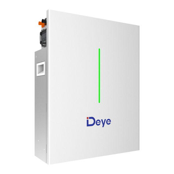
Spring series LFP Battery
RW-F10.2
Version V1.4

Advertisement

loading
Need help?

Need help?

Do you have a question about the Spring Series and is the answer not in the manual?

Questions and answers

Summary of Contents for Deye Spring Series

  • Page 1 User Manual Spring series LFP Battery RW-F10.2 Version V1.4...
  • Page 2 Documents must be stored carefully and be always available. Content may be updated or modified periodically due to product update iterations. The manual is subject to change without prior notice. The latest manual can be acquired via service-ess@deye.com.cn (www.deyeess.com). 1 Safety Introductions Reminding 1)It is very important and necessary to read the user manual carefully (in the accessories) before installing or using battery.
  • Page 3 RW-F10.2 lithium iron phosphate battery is one of new energy storage products developed  and produced by DEYE, it can be used to support reliable power for various types of equipment and systems.  RW-F10.2 is especially suitable for application scene of high power, limited installation space and long cycle life.
  • Page 4 6)Battery module auto networking(No DIP switch code), easy maintenance, support Deye remotely monitoring and upgrade. Also supports Deye inverters to form a stack all-in- one system. 7)Use environmental protection materials, the whole module non-toxic, pollution-free.
  • Page 5 1. BMS Switch 7. Handle 2. Battery negative- 8. Grounding bolt 3. Battery positive+ 9. Parallel communication port OUT 4. Inverter CAN/RS485 port PCS 10. Breather valve 5. Micro circuit breaker 11. Battery indicators 6. Parallel communication port IN BMS Switch BMS Switch: to turn ON/OFF the whole battery BMS standby, no power output.
  • Page 6: Grounding Bolt

    LED Status Indicators Instructions Red on the right and green on the left, long bright if equipment protected. Error : SOC : Battery capacity indicator, green light strip. Condition Error 0%~20% 0%~40% 0%~60% 0%~80% 0%~100% Power off Charge Show SOC & highest LED blink Discharge or Idle Show SOC &...
  • Page 7 2.3 Product Size 2.4 Technical Data Main Parameter RW-F10.2 Battery Chemistry LiFePO4 Capacity (Ah) Scalability Max.32 pcs pack (Max.326kWh) in parallel Nominal Voltage (V) 51.2 Operating Voltage(V) 43.2~57.6 Energy (kWh) 10.2 Usable Energy (kWh) Rated DC Power(kW) Max DC Power(kW) Recommend Charge: 100 / Discharge: 100 Charge/Discharge Current (A)
  • Page 8 [1] DC Usable Energy, test conditions: 90% DOD, 0.5C charge & discharge at 25°C. System usable energy may vary due to system configuration parameters. [2] The current is affected by temperature and SOC. [3] Conditions apply, refer to Deye Warranty Letter. [4] Made in China 2.5 Product application solutions The following illustration shows basic application of this battery.
  • Page 9 3 Parts List Check the equipment before installation. Please make sure nothing is damaged in the package. You should have received the items in the following package. 4 Preparations for Installation 4.1 Explanation of Symbol ~ 8 ~...
  • Page 10 4.2 Tools These tools are required to install the battery. ~ 9 ~...
  • Page 11 NOTE: Use properly insulated tools to prevent accident tale electric shock or short circuits. If insulated tools are not available, cover the entire exposed metal surfaces of the available tools, except their tips, with electrical tape. 4.3 Safety Gear It is recommended to wear the following safety gear when dealing with the battery pack. 5 Mounting instructions 5.1 Installation Precaution Lithium battery is designed for indoor use.
  • Page 12 The installation area shall avoid of direct sunlight.  There are no mandatory ventilation requirements for battery module, but please avoid of  installation in confined area. The aeration shall avoid of high salinity, humidity, or temperature. CAUTION If the ambient temperature is outside the operating range, the battery pack stops operating to protect itself.
  • Page 13 ~ 12 ~...
  • Page 14 5.3 Mounting the Battery CAUTION Remember that this battery is heavy! Please be careful when lilting out from the package. 5.3.1 Wall-Mounted method a) Keep a distance of more than 400mm from the ground. After fixing the wall bracket, put a sticker on the right side (between 90 and 95mm).
  • Page 15 Figure 5-1 d)Use the 8 screws of M6*10 to fix the backplane to the back of the battery as shown in Figure 5-2. Figure 5-2 e) Then lifting the RW-F10.2 along the position of the sticker , push it on the wall bracket. ~ 14 ~...
  • Page 16 Unit: mm f) Fasten the screw head of the expansion bolt to finish the mounting. g) Carry the battery and holding it, Fix the battery on the plate after fixing the hanging plate to the wall. Ensure that the upper and lower positions of the battery backplane hook are accurately buckled on the hanging plate, as shown in Figure 5-3.
  • Page 17 5.3.2 Floor-Mounted method ix the support with screws(M10*20). a)F b)Fix the height of the expansion frame with screws(M8*70). The distance between the holes of the retractable support is 25mm. The maximum length of the retractable bracket is 485mm and the minimum length is 335mm. And make sure the wall fixing plate is attached to the wall to complete the installation.
  • Page 18 c) Use the 4 screws of M6*10 to fix the left and right retaining ears to the back of the battery, as shown in Figure 5-4. Figure 5-4 d) Stand the battery on the side of the wall, mark the location of the fixing hole, Choose the recommend drill head (as shown in below picture) to drill 2 holes on the wall,100- 110mm deep, as shown in Figure 5-2 and Figure 5-5.
  • Page 19 e) Use a proper hammer to fixing the battery to the wall, fit the expansion bolt into the holes, as shown in Figure 5-2. Adjust the left and right screws to the appropriate position to ensure that the battery is perpendicular to the ground, as shown in Figure 5-6.
  • Page 20 5.4 Batteries in parallel 5.4.1 mode 1 (It is suitable for scenarios where the inverter power ≤ 15kW) Parallel CAUTION Cable requirements: The cross-sectional area of the cable must be at least 70 square millimeters. It should be noted that the maximum current of the first battery is 250A (inverter power must not exceed 15kW), exceeding 250A will cause heating of the connectors and cable, and in severe cases, it will cause a fire accident.
  • Page 21 or larger capacity systems: ~ 20 ~...
  • Page 22 5.5 Electrical schematic diagram This diagram is for each battery module. 5.6 Battery connected to inverter For the Australian Market, an overcurrent protection and isolation device that isolates both positive and negative conductors simultaneously is required between the battery system and inverter.
  • Page 23 Two batteries connected to inverter Three batteries connected to inverter ~ 22 ~...
  • Page 24 5.7 Visual Inspection of the Connection After connecting the battery, check for: Usage of positive and negative cables.  Connection of the positive and negative terminals.  All the bolts are tightened.  Cables fixation and the appearance.  The installation of the protecting cover. ...
  • Page 25 Separate monitoring: Use the can box to connect the IN or OUT communication port of the battery pack, and open the host computer of Deye to read the information of the battery pack.
  • Page 26 Separate monitoring: Use the can box to connect the IN or OUT communication port of the battery pack, and open the host computer of Deye to read the information of the battery pack.
  • Page 27 6 Inspection, Cleaning and Maintenance 6.1 General Information The battery product is not fully charged. It is recommended that the installation be  completed within 3 months after arrival; During the maintenance process, do not re-install the battery in the battery product. ...
  • Page 28 The battery product should be stored in a dry, cool, and cool environment;  Generally, the maximum storage period at room temperature is 6 months. When the  battery is stored over 6 months, it is recommended to check the battery voltage. If the voltage is higher than 51.2V, it can continue to store the battery.
  • Page 29 charging state. recovered due to Cells are not consistent. The protection against The battery voltage is capacity of some cells abnormality greater than 58.4 V. deteriorates too fast or the contact local internal resistance of some engineers to cells is too high. rectify the fault.
  • Page 30 the level of chemical purity after analysis. The filter residue is dissolved with sulfuric acid and hydrogen peroxide, so that lithium iron phosphate enters the solution in the form of Fe and Li , and is separated from carbon black and carbon coated on the surface of lithium iron phosphate. After filtration and separation, the pH value of the filtrate is adjusted with NaOH and ammonia water.
  • Page 31 Figure 9-1: Class 9 Miscellaneous Dangerous Goods and UN Identification Label ~ 30 ~...

This manual is also suitable for:

Rw-f10.2