
Related Manuals for Micronics UX5000


Summary of Contents for Micronics UX5000
- Page 1 Installation & Maintenance Instructions MICRONICS UX5000 Clamp-on Flow Meter for use in Hazardous Environments Supplied by Call us on +44 (0)118 916 9420 | Email info@247able.com...
- Page 2 5000 UX5000 Non-Invasive Flow Meter User Manual Micronics Ltd, Kenfig Industrial Estate Margam, Port Talbot, SA13 2PW, UK Telephone: +44(0)1628 810456 E-mail: sales@micronicsltd.co.uk www.micronicsflowmeters.com...
- Page 4 DOCUMENT AUTHORITY Issue Date Originator Approved October 24 Approved Micronics Ltd The British Rototherm Co...
- Page 6 Micronics UX5000 User Manual CONTENTS CERTIFICATION AND COMPLIANCE ..............1 Certification and Compliance ....................1 1.1.1 EMC, Safety, Weee, RoHS ..................1 1.1.2 Hazardous Area Classification ATEX, IECEx & UKEX..........1 1.1.3 DCSIU Hazardous Area Label ................1 1.1.4 RMU Hazardous Area Labels ................. 2 1.1.5...
- Page 7 3.8.1 Mounting the DCSIU ................... 17 3.8.2 Mounting the RMU ..................... 18 SOFTWARE CONFIGURATION ................20 Software Installation ......................20 UX5000 tab ........................21 Units tab ..........................24 Fluid 1/2 tab ........................25 4.4.1 Application Temperature ..................26 4.4.2 Fluid Selection ..................... 26 Select the fluid type from the drop down menu options: ..........
- Page 8 Micronics UX5000 User Manual 4.12 BluetoothLE ........................42 GUIDERAIL ASSEMBLY ..................43 Transducers in Reflex Mode ..................... 43 Using Transducers in Diagonal Mode ................44 Attach the PT100 Probe(s) ....................45 MEASUREMENT MODE ..................45 TROUBLESHOOTING ..................47 No flow reading ......................... 47 Poor or inconsistent readings ...................
- Page 9 Figure 9: RMU: mounting to a vertical pipe..................19 Figure 10: RotoFlow software: UX5000 page at startup ..............21 Figure 11: UX5000 tab in Configure mode (for Flow, Channel 1 only) ..........22 Figure 12: Units tab (for single channel configuration) ............... 24 Figure 13: Fluids tab (for single fluid configurations) ................
- Page 10 Micronics UX5000 User Manual CERTIFICATION AND COMPLIANCE 1.1 Certification and Compliance 1.1.1 EMC, Safety, Weee, RoHS • 2014/30/EU (EMC Directive) • EN 61326-1:2021 Electrical equipment for measurement, control and laboratory use • 2014/35/EU (Low Voltage Directive) • EN IEC 61010-1:2010 +A1:2016 Safety requirements for electrical equipment for measurement, control and laboratory use •...
- Page 11 UX5000 User Manual Micronics 1.1.4 RMU Hazardous Area Labels ATEX & IECEx LABEL NRTL (NORTH AMERICAN) LABEL 1.1.5 Ultrasonic Flow Sensor Hazardous Area Labels ATEX & IECEx LABEL NRTL (NORTH AMERICAN) LABEL Explanation of Symbols Indicates separate collection for Indicates that the product has been...
- Page 12 All installation activities must adhere strictly to relevant codes of practice and safety protocols, in accordance with local and national standards governing the use of electrical equipment within the specific installation location of the UX5000. Installation procedures should be entrusted solely to competent individuals.
- Page 13 UX5000 User Manual Micronics The DCSIU system will be equipped with either a line bushing or gland at the DCSIU <> RMU cable entry point, which will be sealed with a small bead of thread sealant. It is imperative that this sealant is not tampered with or loosened.
- Page 14 How Does It Work? The UX5000 uses a cross correlation transit time algorithm to provide accurate flow measurements. Figure 1: Principle of Transit-Time operation An ultrasonic beam of a given frequency is generated by applying a repetitive voltage pulse to the transducer crystals.
- Page 15 UX5000 User Manual Micronics direction, being sent from the upstream transducer to the downstream transducer as shown in the lower half of Figure 1. The speed at which the ultrasound is transmitted through the liquid is accelerated slightly by the velocity of the liquid through the pipe. The subsequent time difference T1-T2 is directly proportional to the liquid flow velocity.
- Page 16 Micronics UX5000 User Manual Figure 2: UX5000 Contents Issue 1.3 Oct-24 Page 7...
- Page 17 UX5000 User Manual Micronics System Configuration The following diagram shows the typical configuration of a UX5000 system: DCSIU Guide rail Pt100 RTD and sensors Probe Mounting bracket Dual channel kit Figure 3: UX5000 system configuration Page 8 Issue 1.3 Oct-24...
- Page 18 Micronics UX5000 User Manual INSTALLATION Unpacking The packed unit weighs 12kg. Please handle with care and pay attention to people and equipment when transporting. The instrument should be stored or transported in its original packaging. If the instrument needs to be transported, please ensure it is adequately packed to prevent any damage to the contents or injury to personnel.
- Page 19 MICRONICS LTD ACCEPTS NO RESPONSIBILITY OR LIABILITY IF PRODUCT HAS NOT BEEN INSTALLED IN ACCORDANCE WITH THESE INSTRUCTIONS. For accurate measurements, the UX5000’s guide rail and sensors must be installed at a position where the fluid flows uniformly. Flow profile distortions can result from upstream disturbance such as bends, tees, valves, pumps, and other similar obstructions.
- Page 20 Micronics UX5000 User Manual To obtain the most accurate results, the condition of both the liquid and the pipe must be suitable to allow ultrasound transmission along the predetermined path. In many applications, an even flow velocity profile over a full 360° is unattainable due, for example, to the presence of air turbulence at the top of the flow and possibly sludge at the bottom of the pipe.
- Page 21 UX5000 User Manual Micronics The recommended cable is given below, in addition please ensure all work and materials are selected to meet the local standards. Page 12 Issue 1.3 Oct-24...
- Page 22 Micronics UX5000 User Manual Table 1: Cable properties Property Description Comments Cable 0.5mm² / 2PR BS5308 PT1 Type 2 Collective Screen Black RP15 16 / 0.2mm² Conductor Size 0.5mm² - 16/0.2mm² - 20AWG Number of Conductors 2 Pair Number of pairs will be dependent...
- Page 23 UX5000 User Manual Micronics Opening and Closing the DCSIU Enclosure The rear cover of the DCSIU is secured by a socket screw. Loosen, but do not remove, this screw to detach the cover for internal access. When reattaching the screw cover, ensure a smooth rotation by hand.
- Page 24 Micronics UX5000 User Manual Relay Outputs 1/2/3 4-20mA (Output 1) 4-20mA (Output 2) Power Modbus Figure 6: Terminal blocks and connectors 3.6.2 Power Supply The DCSIU’s recommended operating voltage is between 21-24VDC. The Maximum voltage is 26V supply. It is internally protected with a 500mA 5x20 Glass Fast Acting Fuse. This in turn supplies power to the RMU through the DCSIU/RMU cable and also provides two analogue (4-20mA) outputs and 3 opto-isolated relay outputs.
- Page 25 UX5000 User Manual Micronics DCSIU Description SUPPLY + Power Supply + (nominal 24 VDC) RS 485 Cable included DCSIU (Modbus RTU control interface) cable length up to 50m (junction boxes 250 meters) OUTPUT + (1,2) Analogue Output + (4..20mA or 0..5V) OUTPUT –...
- Page 26 THE DCSIU IS HEAVY PLEASE HANDLE WITH CARE. USE TWO HANDS The UX5000 DCSIU should be mounted to allow access of the field terminals and recommended at eye level to allow a clear view of the display. The enclosure is supplied with a bracket for pipe mounting or 2”...
- Page 27 UX5000 User Manual Micronics Figure 7: DCSIU Mounting bracket: pipe (left) and wall (right) mounting options Pipe Mounting The mounting kit includes a U-bolt, M8 washers and nuts appropriate for attaching the bracket to a horizontal or vertical 2” (60.03mm) OD pipe.
- Page 28 Micronics UX5000 User Manual INSTALLED RMU AND PIPE ON WHICH THE SENSORS WILL BE FITTED WILL BE LIMITED BY THE LENGTH OF THE SENSOR CABLES (5M STANDARD) Figure 9: RMU: mounting to a vertical pipe Pipe Mounting The RMU can be attached to a horizontal or vertical pipe with a diameter between 25mm (1”) and 180mm (7”).
- Page 29 6. Click on the Start button for communications. Bluetooth Connection: 1. Click on the Bluetooth tab. 2. Search for devices and select UX5000. 3. Once connected, press the Start button. A flashing green status indicator confirms a successful connection. A flashing red indicator indicates failure to establish a connection.
- Page 30 UX5000 tab Figure 10: RotoFlow software: UX5000 page at startup The UX5000 page has Configure and Measure modes. In Configure mode, the settings for each channel are displayed in several tabbed pages. To enter this mode, you need to choose the configuration unit setup.
- Page 31 4. Click on the Save button to confirm the selections. Settings for the chosen configuration are now displayed on a series of tabbed pages. Figure 11: UX5000 tab in Configure mode (for Flow, Channel 1 only) Table 4: RotoFlow Setup Menus...
- Page 32 Micronics UX5000 User Manual System/ID/RS485 System information. Configuration(s) System settings. Bluetooth LE Issue 1.3 Oct-24 Page 23...
- Page 33 UX5000 User Manual Micronics Units tab The Units tab allows you to select display units according to your preference. Below are the available options for unit selection. Figure 12: Units tab (for single channel configuration) Table 5: Unit tab options...
- Page 34 Micronics UX5000 User Manual Units of Metric Imperial US Imperial Measurement /hour) Total Volume Litres (l) gallons (gal) US gallons (USgal) Cubic metres (m Mass Flow kilograms per second pounds per second pounds per second (kg/s) (lbs/s) (lbs/s) kilograms per minute...
- Page 35 UX5000 User Manual Micronics Figure 13: Fluids tab (for single fluid configurations) 4.4.1 Application Temperature Use System Temperature: You have the flexibility to input the application temperature manually or utilize the system temperature using a PT100 Temperature sensor. This sensor enables dynamic flow reading and ensures a more accurate setup based on real-time temperature data.
- Page 36 Micronics UX5000 User Manual Pipe(s) tab Figure 14: Pipes tab (for single pipe configurations) 4.5.1 Pipe Selection Section In this section, you will select the appropriate options for the pipe(s) based on your specific requirements. The options may vary depending on whether you are configuring a single channel (Pipe 1) or a dual channel/dual path setup (which will include Pipe 2).
- Page 37 UX5000 User Manual Micronics 4.5.3 Manual Inputs For accurate configuration, manual inputs are required for the following parameters: • Internal Diameter Measure the inner diameter of the pipe using an appropriate measuring tool or obtain from the pipe datasheet. This measurement is crucial for accurate flow calculations.
- Page 38 Micronics UX5000 User Manual 4.6.1 Liner Options The system offers various liner options to accommodate diverse applications. Each liner type possesses unique characteristics suited to different operational requirements: • PVC PVC liners provide a cost-effective solution with excellent chemical resistance and flexibility.
- Page 39 UX5000 User Manual Micronics Sensor(s) tab Figure 17: Sensors tab (for single channels) Single Channel Sensor Selection For a single channel setup, Sensor 1 is recommended. Dual Path/Dual Channel Sensor Selection For a dual path or dual channel setup, Sensor 1 & Sensor 2 is required.
- Page 40 Micronics UX5000 User Manual Diagnostics tab Figure 18: Diagnostics tab (for channel 1) This section is designed for viewing purposes only. The Physical Parameters Tab the parameters displayed represent the readings obtained directly from the unit's sensors. These readings are presented in the units selected in the "Unit Selection"...
- Page 41 UX5000 User Manual Micronics meters per second (m/s) or feet per second (ft/s) and provides crucial information about the flow dynamics. • Flow Volume The volume of fluid passing through a specified point in the system over a certain period. It is typically measured in units like cubic meters (m^3) or gallons (gal) and helps in quantifying the amount of fluid movement.
- Page 42 Micronics UX5000 User Manual Typical values 2-inch pipe, double reflex mode, water : 30ns/m/s 4-inch pipe, single reflex mode, water: 30ns/m/s 12-inch pipe, single reflex mode, water: 90ns/m/s Zero Cut-Off The Zero Cut-off is a velocity (mm/s) entered by the user to set the flow velocity, below which, the meter will read zero.
- Page 43 UX5000 User Manual Micronics This is the measured value of the receiver amplifier gain required to achieve a received signal level suitable for processing. The value is represented in decibels. The value depends on the pipe material, fluid type, signal mode and installation quality.
- Page 44 Micronics UX5000 User Manual This value indicates the current operating status of the meter. Typical values: Status: 0 – No errors • Bit 0: No signal • Bit 1: Flow engine calculation error • Bit 2: Memory comms error • Bit 3: Flow engine comms error •...
- Page 45 UX5000 User Manual Micronics 4.9.1 Output Configuration: Enable or disable Output 1 and Output 2 individually as required. Each output can be assigned to Channel 1 or Channel 2 for flexibility in signal routing. 4.9.2 Analog Output Specifications: Each output can represent parameters such as Flow Velocity, Flow Volume, Mass Flow or Temperature.
- Page 46 Micronics UX5000 User Manual • Disabled Relay 1/2/3 is inactive. • On Channel 1 or On Channel 2 Relay 1/2/3 can be configured to be active on either Channel 1 or Channel 2. • Contacts Relay 1/2/3 can have Normally Open (N.O.) or Normally Closed (N.C.) contacts.
- Page 47 UX5000 User Manual Micronics 4.10 System/ID/RS485 tab Figure 20: System/ID/RS485 tab 4.10.1 Identification • Unit Model The specific model name or number of the unit. This helps in identifying the exact type or variant of the unit being used. • Unit Type A categorization of the unit based on its functionality or application.
- Page 48 Micronics UX5000 User Manual • Processing Firmware Version The version number of the firmware responsible for processing data collected by the unit. Updates to this firmware may improve data accuracy, analysis capabilities, or integration with other systems. • Hardware Version A designation indicating the specific hardware configuration or revision of the unit.
- Page 49 UX5000 User Manual Micronics numerical value ranging from 1 to 247, although certain reserved addresses may have specific functions. Example Configuration: • Baud Rate: 9600 bps • Parity: Even • Stop Bits: 1 • Slave Address: 1 NOTE: ENSURE THAT ALL DEVICES ON THE MODBUS RS485 NETWORK ARE CONFIGURED WITH COMPATIBLE PARAMETERS TO FACILITATE SUCCESSFUL COMMUNICATION.
- Page 50 Micronics UX5000 User Manual 4.11 Configuration(s) These setting determine how data is displayed in Measure mode. Figure 21: Configuration(s) tab (for single channel use) • Temperature update period (sec) This refers to the frequency at which the device updates the temperature readings. It determines how often the system checks for changes in temperature.
- Page 51 UX5000 User Manual Micronics • Sample period This defines the number of times reading is taken. • User Velocity Calibration Factor This allows application-specific calibration. Once your choice has been selected, remember to click on Save to apply the changes.
- Page 52 Micronics UX5000 User Manual 5 GUIDERAIL ASSEMBLY Transducers in Reflex Mode FOR DUAL CHANNEL SYSTEMS, REPEAT THIS PROCEDURE FOR EACH GUIDE RAIL. Figure 22: Guiderail and sensor assembly 1. Set the guiderail to the separation distance given on the Diagnostics 1/2 screen after entering all the relevant pipe, fluid and liner data.
- Page 53 UX5000 User Manual Micronics o Fit the blue cable to D1 (Downstream). o Fit the red cable to U1 (Upstream). Using Transducers in Diagonal Mode For Diagonal Mode, the transducer guide rails must be fitted on opposite sides of the pipe. It is necessary to accurately mark out the required positions to ensure that the transducers are correctly positioned and aligned along the axis of the pipe, directly opposite each other on a 45°...
- Page 54 • Live SQ (Signal Quality) • Live cumulative total To return to the Measure mode from Configure mode: 1. Select the UX5000 tab. 2. In the Mode box, select Measurement. 3. Click on the Save button. Upon successful completion of the above steps, the tabs at the top of the configuration software interface will reduce to display only the following options: •...
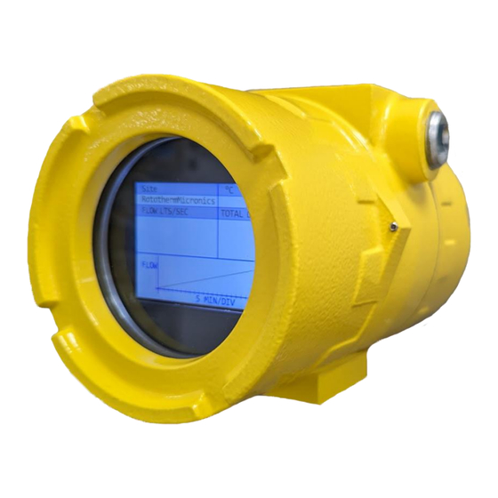
- Page 55 UX5000 User Manual Micronics • Diagnostics 2 • BluetoothLE Figure 24: Measure mode (shown for dual channel) Measurement mode allows the set up of the Display unit from the options given below: • Site Name This is a free type area. In the example it is given as Channel 1234. If using 2 channels we recommend that the Site Names are different to ensure easy recognition of which Pipe date is being shown on the display.
- Page 56 Micronics UX5000 User Manual 7 TROUBLESHOOTING When the unit has been installed and configured correctly: • In Measure mode (see Figure 24), the screen displays a flow value with a signal quality of at least 40. • Check on the Diagnostics tab in the System Diagnostics group (see page 32) that: ▪...
- Page 57 The UX5000 flow meter has been designed to work on the pipe materials shown in drop down. If other is chosen and readings are problematic please contact our technical team for help. Please note that testing has shown that there is limited compatibility with multi-layer composite pipes.
- Page 58 Micronics UX5000 User Manual Error and Warning Messages Error messages are displayed as a number in Status Channel on the Diagnostics tab (see page 31). Contact Micronics if other messages are shown. 7.6.1 Error Messages Status Byte Error Meaning Value...
- Page 59 UX5000 User Manual Micronics APPENDIX Specification UX5000 Accuracy up to 0.5% with Process Calibration Repeatability ±0.15% Fluid Types All acoustically conductive liquids with <3% Particlulate Pipe Material Many including Steel, Stainless Steel, Copper, Plastic Pipe Diameter (OD) 2” to 12” (50-300mm)
- Page 60 Micronics UX5000 User Manual Size 160mm x 100mm x 79mm Operational Temperature -20 to 60°C Temperature Sensor Connections M8 male waterproof connector DCSIU Connection M12 male waterproof connector Sensor Connections TNC waterproof connector Cable Distance from Sensor 5m standard (10m optional)
- Page 61 UX5000 User Manual Micronics Spares For replacement parts please see ordering code below. For calibration and/or repair of unit please contact service@micronicsltd.co.uk. Spares UX5000 Part Number Temperature Probe kit: MC-1T05 Pt100 Temperature Sensor, Stainless Steel Cable Tie, Heat Sink Compound...
- Page 62 Rototherm. Secure arrangements must be made to ensure that an electrical supply cannot be connected to the circuits feeding into or from the UX5000 during any period when the front cover or electrical entry glands are not fully secured.
- Page 63 UX5000 User Manual Micronics Dimensions 8.4.1 General Assembly 8.4.2 Display Unit (Digital Control and Signal Interface Unit) General Assembly Page 54 Issue 1.3 Oct-24...
- Page 64 Micronics UX5000 User Manual 8.4.3 Remote Measurement Unit (RMU) General Assembly 8.4.4 Sensor Guiderail Assembly The sensor bracket assembly is configured for reflex (2 path) operation. For direct (1 path) operation the guide rail will not be used. Issue 1.3 Oct-24...
- Page 65 UX5000 User Manual Micronics Acronym Glossary DCSIU Digital Control and Signal Interface Unit Remote Measurement Unit °C Celsius (Metric Temperature) Millimetre (Metric Length) Metres per second (Metric Flow Velocity) Kilogram (Metric Mass) Litres per second (Metric Flow Volume) l/min Litres per minute (Metric Flow Volume)
Need help?
Do you have a question about the UX5000 and is the answer not in the manual?
Questions and answers