Table of Contents
Advertisement
Quick Links
UF3300FM:
UF3300HM:
Micronics Ltd, Knaves Beech Business Centre,
Davies Way, Loudwater, High Wycombe, Bucks HP10 9QR
Telephone: +44(0)1628 810456
UF3300
Wall-Mounted Ultrasonic Flow Meter
Wall-Mounted Ultrasonic Heat Meter
User Manual
E-mail:
www.micronicsflowmeters.com
sales@micronicsltd.co.uk
Issue 1.0
Advertisement
Table of Contents
Troubleshooting

Subscribe to Our Youtube Channel
Related Manuals for Micronics UF3300 Series


Summary of Contents for Micronics UF3300 Series
- Page 1 UF3300 UF3300FM: Wall-Mounted Ultrasonic Flow Meter UF3300HM: Wall-Mounted Ultrasonic Heat Meter User Manual Micronics Ltd, Knaves Beech Business Centre, Davies Way, Loudwater, High Wycombe, Bucks HP10 9QR Telephone: +44(0)1628 810456 E-mail: sales@micronicsltd.co.uk www.micronicsflowmeters.com Issue 1.0...
-
Page 3: Table Of Contents
Micronics UF3300 User Manual CONTENTS INTRODUCTION ..............................1 General Description ......................1 How Does It Work? ......................2 1.2.1 Reflex (V) Mode ......................4 1.2.2 Double Reflex (W) Mode ..................... 4 1.2.3 Triple Reflex (WV) Mode ..................... 4 1.2.4 Quadruple Reflex (WW) Mode ..................4 1.2.5... - Page 4 Micronics UF3300 User Manual 3.5.2 Resetting Totals ......................31 MANAGING NAMED SITES ..........................32 View/Edit Site Data ......................32 Selecting an Existing Site ....................33 Adding a New Site ......................34 Changing a Site Name ...................... 34 Editing Site Data ....................... 35 Changing Calibration Parameters ..................
- Page 5 Micronics UF3300 User Manual 10.3.4 Data Logging Errors & Messages ................61 10.3.5 Set-up and Other Errors & Messages ................ 63 10.4 Diagnostics ........................65 10.4.1 Advanced Diagnostics ....................66 APPENDIX ................................. 67 11.1 Specification ........................67 11.2 Declaration of Conformity ....................70 Page iii Issue 1.0 April 2021...
-
Page 7: Introduction
Micronics UF3300 User Manual INTRODUCTION General Description The UF3300 is a wall-mounted flow meter (and heat meter depending on configuration options) that uses clamp-on transducers to enable the flow of a liquid within a closed pipe to be measured accurately without needing to insert any mechanical parts through the pipe wall or protrude into the flow system. -
Page 8: How Does It Work
Micronics UF3300 User Manual Typical applications: • River water • Seawater • Potable water • Demineralised water • Treated water How Does It Work? The UF3300 flow meter uses a cross correlation transit time algorithm to provide accurate flow measurements. - Page 9 Micronics UF3300 User Manual Reflex (V) Mode (single bounce) Reflex (W) Mode (double bounce) Reflex (WV) Mode (triple bounce) Reflex (WW) Mode (quadruple bounce) Diagonal Mode Figure 2 Operating modes Issue 1.0 April 2021 Page 3...
-
Page 10: Reflex (V) Mode
Micronics UF3300 User Manual 1.2.1 Reflex (V) Mode This is the mode most commonly used. The two transducers (U & D) are attached to the pipe in line with each other and the signals passing between them are reflected by the opposite pipe wall. -
Page 11: Package Contents
Micronics UF3300 User Manual Package Contents The unit consists of the following components: UF3300 electronics unit Incorporating keypad and backlit display. Transducer cables x 2, (2m) Guide rail (optional second rail for diagonal configuration) For use with A or B type transducers... -
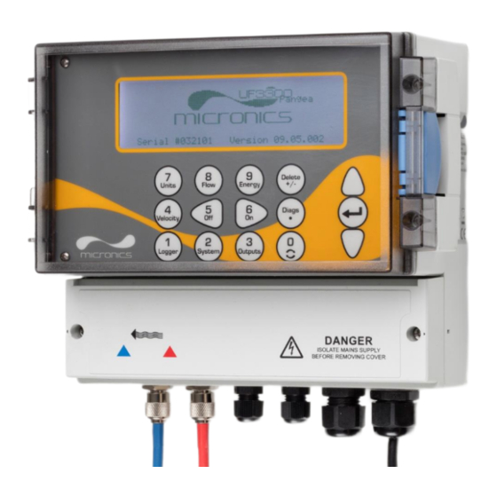
Page 12: Display And Connectors
Micronics UF3300 User Manual Display and Connectors The UF3300 unit is microprocessor-controlled, operated through a menu system using an inbuilt LCD display and keypad. It can display the instantaneous fluid flow rate or velocity, together with totalised values. The instrument can also provide a variable current or variable ‘pulse’ (volumetric, energy, or flow frequency) output that is proportional to the detected flow rate. - Page 13 Micronics UF3300 User Manual UF3300 units can also act as a data logger (requires data logger option). When operating in the data logger mode, data is saved to non-volatile internal storage. This data may be downloaded at a later date via a flash drive inserted in the USB socket. Data is saved as text in a CSV file which may then be loaded directly into a program such as Microsoft™...
-
Page 14: Keypad
Micronics UF3300 User Manual Keypad The instrument is configured and controlled via a 15-key tactile membrane keypad, as shown in Figure 5. Numerical keypad with Scroll up dual function keys ENTER (SELECT) Scroll down Figure 5 UF3300 keypad 1.5.1 Dual Function Numerical Keypad The block of keys shown in the centre of the keypad in Figure 5 are dual function keys. -
Page 15: Menus And The Menu Selection Keys
Micronics UF3300 User Manual No function - reserved for future use Cycle through the available display units Switch to the Read Flow display from the Read Velocity display or Read Energy display (Heat Meter versions only) Heat Meter versions only: switch to the Read Energy display from the Read... - Page 16 Micronics UF3300 User Manual Some menus have more options than can be shown on the screen at the same time, in which case the ‘overflowed’ choices can be brought into view by continuing to scroll beyond the lowest visible item.
-
Page 17: Installation
Standard transducer cables are 5 metres in length with 10 metre cables being optionally available. Where, for operational reasons, it is not possible to mount the instrument this close to the sensors, bespoke cables of up to 100m can be provided – consult Micronics Ltd for further information and availability. -
Page 18: Connections
Micronics UF3300 User Manual Connections This section explains how to connect power and signal cables to the terminal blocks inside the wall mount unit. The transducer cables attach to sockets on the left side of the terminal block. Other cables enter the instrument through the four cable glands provided and are connected to terminal blocks which are located behind a safety cover (Figure 8). -
Page 19: Control & Monitoring Cables
Micronics UF3300 User Manual LETHAL VOLTAGES! ENSURE THE POWER CABLE IS ISOLATED FROM THE MAINS SUPPLY. DO NOT APPLY MAINS VOLTAGE WITH THE TERMINAL COVER REMOVED. EXTERNAL POWER SUPPLY MUST BE CLASS 2 RATED. IMPORTANT: IT IS THE RESPONSIBILITY OF THE INSTALLER TO CONFORM TO THE REGIONAL VOLTAGE SAFETY DIRECTIVES WHEN CONNECTING THE UF3300 TO A POWER SUPPLY USING A MAINS-RATED TRANSFORMER. -
Page 20: Usb Connector
Micronics UF3300 User Manual 2.3.3 USB Connector A USB connector is available at the left-hand side of the enclosure. This can be used to download logged data onto a USB memory stick (see page 42). Figure 9 USB socket on left side of UF3300 enclosure Page 14 Issue 1.0 April 2021... -
Page 21: Positioning The Transducers
Micronics UF3300 User Manual Positioning the Transducers For accurate measurements, the transducers must be installed at a position where the fluid flows uniformly. Flow profile distortions can result from upstream disturbance such as bends, tees, valves, pumps and other similar obstructions. To ensure a uniform flow profile, the unit must be mounted away from any cause of flow disturbance. -
Page 22: Attaching The Transducers
IMPORTANT: DO NOT EXPECT TO OBTAIN ACCURATE RESULTS IF THE UNIT IS POSITIONED CLOSE TO ANY OBSTRUCTION THAT DISTORTS THE UNIFORMITY OF THE FLOW PROFILE. MICRONICS LTD ACCEPTS NO RESPONSIBILITY OR LIABILITY IF PRODUCT HAS NOT BEEN INSTALLED IN ACCORDANCE WITH THESE INSTRUCTIONS. -
Page 23: Fitting The Transducers
Micronics UF3300 User Manual 2.5.3 Fitting the Transducers Tighten each transducer clamp clockwise until it is close to the top of the transducer (Figure 12, left). This is necessary in order to prevent the acoustic couplant touching the pipe when the transducer is initially inserted into the guide rail –... - Page 24 Micronics UF3300 User Manual Align edge of transducer with ‘0’ on ruler scale Figure 14 Aligning edge of downstream transducer (blue) with zero on ruler scale Lower the transducer onto the pipe by turning the transducer clamp anti-clockwise until it is ‘finger tight’...
- Page 25 Micronics UF3300 User Manual Calculated separation distance Figure 16 Settinging transducer separation 10. Lower the transducers onto the pipe by turning each transducer clamp anti-clockwise until it is ‘finger tight’ (do not use a spanner). Figure 17 shows the final position of the transducers when the transducer clamps are fully tightened.
-
Page 26: Fixing Transducers In Diagonal Mode
Micronics UF3300 User Manual 2.5.4 Fixing Transducers in Diagonal Mode This mode of operation requires two transducer guide rails fitted on opposite sides of the pipe (fitted on a 45° axis with respect to the top of the pipe as in Reflex Mode). If the required transducer separation is 230mm or less, the guide rails can be fitted using the same stainless steel bands (see Figure 18a). - Page 27 Micronics UF3300 User Manual Position the upstream guide rail horizontally on the pipe at 45° with respect to the top of the pipe and secure it in position using the supplied stainless steel banding. Fit the upstream transducer into the guide rail but do not fasten it in position yet.
-
Page 28: Connecting Temperature Probes (Uf3300 Hm Models Only)
Micronics UF3300 User Manual Connecting Temperature Probes (UF3300 HM Models Only) The temperature sensors must be located at the flow and return of the system that is being monitored. The area of pipe where they are to be attached must be free of grease and any insulating material. -
Page 29: Calibrate The Pt100 Sensors (Heat Meter Versions Only)
Micronics UF3300 User Manual Calibrate the PT100 Sensors (Heat Meter versions only) IMPORTANT: THE PT100 SENSORS MUST BE BALANCED BEFORE INITIAL USE, USING THE PROCEDURE DESCRIBED BELOW AND USED WITH THE CABLE LENGTH SUPPLIED. EXTENDING OR SHORTENING THE CABLES WILL NEGATE THE CALIBRATION OF THE SENSORS. -
Page 30: Switching On For The First Time
Micronics UF3300 User Manual Switching on for the First Time READ FLOW DD-MM-YY HH:MM:SS When power is applied, the unit passes through its Q60.0% initial booting sequence and then displays the Flow 27.540 screen. l/min Press the ENTER key to display the Main menu. -
Page 31: Setting The Date & Time
Micronics UF3300 User Manual 2.9.3 Setting the Date & Time System Settings DD-MM-YY H:MM:SS From the MAIN menu, use the Up and Down scroll keys to select Setup Instrument. Press Lock-screen Timeout Back-light mode the ENTER Key. With System selected in the Back-light Timeout Options menu, press the ENTER Key. -
Page 32: Enabling/Disabling Audible Keypress
Micronics UF3300 User Manual If you select TIMED, use the UP/DOWN arrow keys to select to Back-light Timeout. Press the ENTER key. Use the keypad to enter the required timeout interval (5-120s). Press the ENTER key. Select Save Setup & Exit then press the ENTER key to return to the Options menu. -
Page 33: Using The Quick Start Menu
Main Menu.. If the material is not listed, select Other (m/s) and enter the propagation rate of the pipe wall material in metres/sec. Contact Micronics if this is not known. Select CONTINUE and press the ENTER key. Issue 1.0 April 2021... - Page 34 Other (m/s) and enter the propagation rate of the fluid in metres/sec. Contact Micronics if this is not known. Note: If Other is selected, enter the speed of sound (SoS) in metres per second, of the wall material.
-
Page 35: Attaching And Connecting The Flow Sensors
Micronics UF3300 User Manual 10. The Summary screen is displayed. This displays Summary DD-MM-YY HH:MM:SS a summary of the entered parameters and Site: QuickStart informs you of the type of sensor to be used, the Sensor separation: 69.9mm mode of operation and the distance to set up Pipe OD: 114.3mm, ID 98.3mm... -
Page 36: Flow / Energy / Velocity Monitoring
Micronics UF3300 User Manual If the flow reading exceeds a value of +/-99999 in the selected units then the display will change to exponential (or scientific) notation. This is used in Microsoft™ Excel™ and many other software packages. For example, if the display reads 1.0109E5 l/min, this represents 101,090 l/min (1.0109 ×... -
Page 37: Calculating The Average Flow Or Power
Micronics UF3300 User Manual 3.5.1 Calculating the Average Flow or Power To calculate the average flow, wait for the allotted monitoring period to expire then divide the indicated total volume or energy by the time taken. This will give you the average flow in m/s, gals/hour or whatever units you select. -
Page 38: Managing Named Sites
Micronics UF3300 User Manual MANAGING NAMED SITES Setting up the UF3300 system using the Quick Start method described in the previous chapter is the recommended method to use in a ‘one-off’ situation. If you have several site locations that you want to monitor on a frequent basis it is better to set up a named ‘Site’... -
Page 39: Selecting An Existing Site
Micronics UF3300 User Manual Selecting an Existing Site View/Edit Sit DD-MM-YY HH:MM:SS Select View / Edit Site Data from the MAIN ↱Choose from list of sites.. MENU. Add new site.. Site name.. Site01 Select Choose from list of sites. Pipe outside diameter 114.30... -
Page 40: Adding A New Site
Micronics UF3300 User Manual Adding a New Site To add a new site: Select View / Edit Site Data from the MAIN menu. Select Add new site. View/Edit Sit DD-MM-YY HH:MM:SS You are prompted to edit the Site name. Sites are initially named Site01 through to Site11 using the Choose from list of sites.. -
Page 41: Editing Site Data
Micronics UF3300 User Manual Editing Site Data View/Edit Sit DD-MM-YY HH:MM:SS Having selected the appropriate site ↱Choose from list of sites.. (see page 33), scroll through the menu list and Add new site.. enter/change the pipe, sensor and fluid Site name.. -
Page 42: Changing Calibration Parameters
Micronics UF3300 User Manual Changing Calibration Parameters The UF3300 is fully calibrated before it leaves the factory however, the following adjustments are provided to allow you to further ‘fine tune’ your instrument to suit local conditions and the user’s application where necessary. -
Page 43: Adjusting The Calibration Factor
Micronics UF3300 User Manual On the Setting Zfo screen, the Running Average is updated every second. When the measurement has completed, a loud ½ second beep will be heard and the countdown will stop. You may now select Set Zero Flow.. if desired. It should be noted that you may select this setting at any time before the measurement is complete if you are satisfied that the average reading is sufficiently accurate. - Page 44 Micronics UF3300 User Manual Start the UF3300 reading flow. Use the UF3300 totaliser to measure the total flow over a 30-60 minute period, and note the total flow indicated by the reference flow meter over the same period. Calculate the % error between the UF3300 and reference meters. If the error is greater than ±1% calibrate the UF3300 as detailed below.
-
Page 45: Adjusting The Roughness Factor
Micronics UF3300 User Manual 4.6.4 Adjusting the Roughness Factor The roughness factor compensates for the condition of the internal pipe wall, as a rough surface will cause turbulence and affect the flow profile of the liquid. The unit of roughness is mm or inches, depending on the current setting. -
Page 46: Adjusting The Damping Factor
Micronics UF3300 User Manual 4.6.5 Adjusting the Damping Factor By averaging-out the flow rate over several seconds, the Damping factor can be used to smooth out rapid changes in flow rate and prevent large fluctuations in the displayed flow value. It has a range of 0 to 50 s, with a default setting of 10s. -
Page 47: Logging Functions
Micronics UF3300 User Manual LOGGING FUNCTIONS NOTE: THIS CHAPTER ONLY APPLIES TO UF3300 MODELS WITH LOGGING CAPABILITIES. This procedure shows you how to set up a basic logging session under manual start/stop control. Logged data is saved to the instrument’s memory and can be copied to a USB flash drive as a CSV (Comma Separated Values) file at a later time. -
Page 48: Stopping Logging
QUICKSRT.CSV. Also note that for very large files the copy process may take some time, so please be patient. If the copy process take > 2 minutes, the unit may abort the copy. In this case, please contact your distributor or Micronics Ltd. Page 42... -
Page 49: Clearing Log Files
Micronics UF3300 User Manual Clearing Log Files Access the MAIN menu. Data Logger DD-MM-YY HH:MM:SS Select Data Logger from the MAIN menu. Choose from list of sites.. Site name QuickStart Select Choose from list of sites and select the Logger Status.. -
Page 50: Outputs
Micronics UF3300 User Manual OUTPUTS Current Loop Setup The UF3300 allows you to set a current output between zero and 24mA. Standard ranges include 4- 20mA, 0-16mA and 0-20mA. The current range can be used to represent only positive flow, or negative flow ranging into positive flow, or simply negative flows. -
Page 51: Example
Micronics UF3300 User Manual Setting Flow Options (default) Power Options (default) Current Loop Status Off/On Measurement Source Flow Power Value at min output Metric 0 l/min 0 kW Imperial 0 gal/min 0 BTU/hr US Imperial 0 US gal/min 0 BTU/hr Min output current 0.00 mA... -
Page 52: Converting The Measured Current To Flow Rate
Micronics UF3300 User Manual Set Error Current Source to Exceeds Value 10. Set Alarm trigger point to 450 l/min 11. Press Save and Exit to save the setup. 12. Read flow and take a reading on the user’s measuring equipment with the flow turned off. It should show zero as measured by your system (@4.0mA). -
Page 53: Digital Outputs
Micronics UF3300 User Manual Digital Outputs The three digital outputs can each be set up to operate in one of three modes: • Pulse Output (set to Normally Open or Normally Closed contact types) • Alarm Output (set to trigger on Rising or Falling conditions) •... -
Page 54: Pulse Output
Micronics UF3300 User Manual Edit the settings as required (see below). Pulse Output Alarm Output Freq. Output Setting Option/default Setting Option/default Setting Option/default Quantity Volume:1.000 m Direction Rising / Falling Low Freq. 0 Hz Per Pulse Energy:3600.0kJ Pulse 50ms Activation Volume: 0.5m... - Page 55 Micronics UF3300 User Manual Pulse Width 50 milliseconds Pulse output switch open Pulse output switch closed Time (milliseconds) Default Pulse Width Using our example once again, if the flow rate is 150 l/s, 15 pulses would be required to represent it.
- Page 56 Micronics UF3300 User Manual Page 50 Issue 1.0 April 2021...
-
Page 57: Alarm Output
Micronics UF3300 User Manual 6.2.2 Alarm Output An Alarm Output generates an alert when a predetermined value is exceeded or receded for Volume, Flow, Energy or Power, or when Signal is lost or gained. When an alarm is activated, a message is generated on the status line and the corresponding output alarm symbol will flash. - Page 58 Micronics UF3300 User Manual • If the direction is set to Rising, the alarm is triggered when the flow exceeds the Activation Level. The Deactivation Level must be a value less than or equal to the Activation Level. • If the direction is set to Falling, an alarm is triggered when the flow drops below the Activation Level.
-
Page 59: Frequency Output
Micronics UF3300 User Manual Time-out field of the Primary Flow screen (see page 55). The default value is 3 seconds. When the signal is lost it is deemed to have a value of zero, otherwise it has a value of 1. To generate an alarm when signal is lost set the Direction to Falling and set the Activation Level and Deactivation Level to 0.5. -
Page 60: Heat Meter
Micronics UF3300 User Manual HEAT METER NOTE: THIS CHAPTER ONLY APPLIES TO MODELS WITH HEAT METERING CAPABILITIES. From the Main menu, use the Up and Down scroll keys to select Setup Instrument. Press the ENTER Key. The Options screen is displayed. -
Page 61: Primary Flow
Micronics UF3300 User Manual PRIMARY FLOW The Primary Flow screen summarises the flow totals and provides options for their display on the Flow Reading screen. To view the Primary Flow screen: From the Main menu, use the Up and Down scroll keys to select Setup Instrument. Press the ENTER Key. -
Page 62: Maintenance And Repair
The instrument and sensors should be calibrated at least once every 12 months. Contact Micronics or your local service agent for details. When returning product to Micronics make sure it is clean and please notify Micronics if the instrument has been in contact with any hazardous substances. -
Page 63: Troubleshooting
Micronics UF3300 User Manual TROUBLESHOOTING 10.1 Overview If you have a problem with your flow monitoring system, it can be due to any of the following: Faulty If you suspect the instrument is faulty you can check it out using a test block as described instrument on page Error! Bookmark not defined.. -
Page 64: General Troubleshooting Procedure
Micronics UF3300 User Manual 10.2 General Troubleshooting Procedure Figure 21 Troubleshooting chart Page 58 Issue 1.0 April 2021... -
Page 65: Warning And Status Messages
Micronics UF3300 User Manual 10.3 Warning and Status Messages Warnings, errors and status messages appear on the second top line of the display. When there is more than one message to be displayed then the display will cycle between them, unless an error is URGENT. -
Page 66: Heat Meter Errors & Messages
Micronics UF3300 User Manual 10.3.2 Heat Meter Errors & Messages RTD Cold Sensor fault Interpretation: URGENT: The cold sensor probe is either not connected or is faulty. Response: Check the probe is connected. If you are running a unit containing a heat-meter and the probe is not connected, you may simply delete the error and continue. -
Page 67: Data Logging Errors & Messages
Micronics UF3300 User Manual Current loop alarm Interpretation: This message is for information only. It is generated activated when alarm conditions have been met for the current loop. See Section 6.2.2 “Alarm Output” on page 51. Response: Clear the alarm by deleting it and attend to the fault. - Page 68 Micronics UF3300 User Manual Could not delete CSV Interpretation: The internal CSV file associated with the site could file. not be deleted. Response: Try the operation again. If this fails, turn the UF3300 off and then on again. Select the site whose log you wish to remove and attempt to clear the log again.
-
Page 69: Set-Up And Other Errors & Messages
Micronics UF3300 User Manual 10.3.5 Set-up and Other Errors & Messages Too many errors Interpretation: The UF3300 generated too many errors as a result of a fault and some errors may not have been reported. Response: Respond to the errors highlighted. - Page 70 Micronics UF3300 User Manual Site DB failure. Restoring Interpretation: When reading parameters from the database, some default values. site parameters appeared corrupted, so all parameters have been restored to initial values. Response: Re-enter parameters for this site. Press ‘delete’ to remove this error.
-
Page 71: Diagnostics
Micronics UF3300 User Manual 10.4 Diagnostics This feature is designed for advanced users and is intended to provide information that will aid the user to diagnose problems – e.g. no signal strength. When operating in the FLOW or ENERGY (Heat Meter versions only) READING modes you can access a diagnostics screen by pressing the Diags function key. -
Page 72: Advanced Diagnostics
Micronics UF3300 User Manual 10.4.1 Advanced Diagnostics LFF (ns/m/s) Linear Flow Factor in nano seconds per metre per second. Average Velocity (m/sec) A rolling average raw velocity over the last 25 seconds A rolling average ∆T over the last 25 seconds... -
Page 73: Appendix
Micronics UF3300 User Manual APPENDIX 11.1 Specification General Flow Measurement Technique Transit time Flow Velocity Range Minimum Velocity 0.1m/s; Max Velocity 10m/s: Bi-directional. Turn Down Ratio 100:1 Accuracy Pipe ID > 75mm – ±0.5% to ±2% of flow reading for flow rate Accuracy >0.2m/s... - Page 74 Micronics UF3300 User Manual Datalogger (3300L models only) Data Logged Log application details, time, date, flow rate, forward total, reverse total, flow velocity, flow side temperature, return side temperature, temperature difference, power, total energy, signal quality, signal SNR, signal status.
- Page 75 BS EN 61326 - 1:2006, BS EN 61326-2-3:2006 Shipping Information Box Dimensions 480mm x 320mm x 230mm Weight 7.5 kg Volumetric Weight 8.83 kg Micronics reserve the right to alter any specification without notification. Issue 1.0 April 2021 Page 69...
-
Page 76: Declaration Of Conformity
Details of these special measures and limitations to use are available on request, and also contained in the product manuals. Registered Office: Micronics Limited, Knaves Beech Business Centre, Davies Way, Loudwater, Buckinghamshire. HP10 9QR. Web site: www.micronicsflowmeters.com...
Need help?
Do you have a question about the UF3300 Series and is the answer not in the manual?
Questions and answers