Table of Contents
Advertisement
Quick Links
UF3300FM:
UF3300HM:
Kenfig Industrial Estate, Margam, Port Talbot, SA13 2PW
Telephone: +44(0)1656 740551
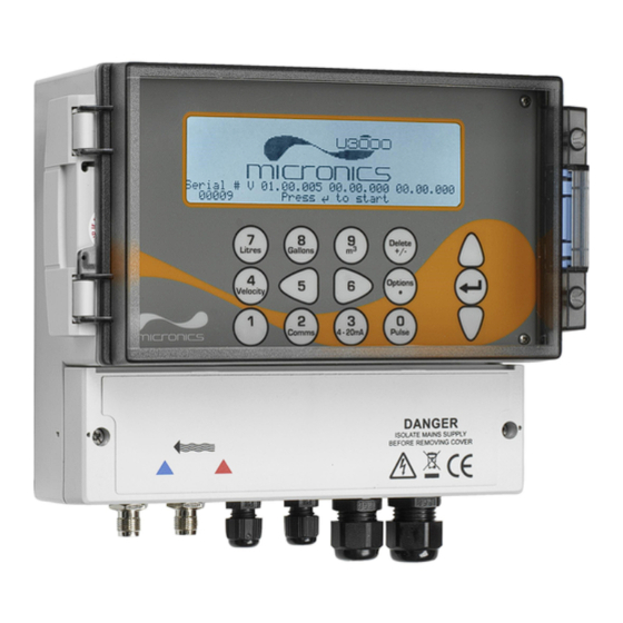
UF3300
Wall-Mounted Ultrasonic Flow Meter
Wall-Mounted Ultrasonic Heat Meter
User Manual
British Rototherm Company LTD.
United Kingdom
E-mail:
www.micronicsflowmeters.com
sales@micronicsltd.co.uk
Issue 1.1
Advertisement
Table of Contents
Troubleshooting

Related Manuals for Micronics UF3300FM


Summary of Contents for Micronics UF3300FM
- Page 1 UF3300 UF3300FM: Wall-Mounted Ultrasonic Flow Meter UF3300HM: Wall-Mounted Ultrasonic Heat Meter User Manual British Rototherm Company LTD. Kenfig Industrial Estate, Margam, Port Talbot, SA13 2PW United Kingdom Telephone: +44(0)1656 740551 E-mail: sales@micronicsltd.co.uk www.micronicsflowmeters.com Issue 1.1...
- Page 3 Micronics UF3300 User Manual Page i Issue 1.1 November 2021...
-
Page 5: Table Of Contents
Micronics UF3300 User Manual CONTENTS INTRODUCTION ..............................4 General Description ......................4 How Does It Work? ......................5 1.2.1 Reflex (V) Mode ......................7 1.2.2 Double Reflex (W) Mode ..................... 7 1.2.3 Triple Reflex (WV) Mode ..................... 7 1.2.4 Quadruple Reflex (WW) Mode ..................7 1.2.5... - Page 6 Micronics UF3300 User Manual 3.5.1 Calculating the Average Flow or Power ..............36 3.5.2 Resetting Totals ......................36 MANAGING NAMED SITES ..........................37 View/Edit Site Data ......................37 Selecting an Existing Site ....................38 Adding a New Site ......................39 Changing a Site Name ......................
- Page 7 Micronics UF3300 User Manual 10.3.3 Current Loop and Digital Output Errors & Messages ..........65 10.3.4 Data Logging Errors & Messages ................66 10.3.5 Set-up and Other Errors & Messages ................ 68 10.4 Diagnostics ........................70 10.4.1 Advanced Diagnostics ....................71 APPENDIX .................................
-
Page 8: Introduction
Micronics UF3300 User Manual INTRODUCTION General Description The UF3300 is a wall-mounted flow meter (and heat meter depending on configuration options) that uses clamp-on transducers to enable the flow of a liquid within a closed pipe to be measured accurately without needing to insert any mechanical parts through the pipe wall or protrude into the flow system. -
Page 9: How Does It Work
Micronics UF3300 User Manual Typical applications: • River water • Seawater • Potable water • Demineralised water • Treated water How Does It Work? The UF3300 flow meter uses a cross correlation transit time algorithm to provide accurate flow measurements. - Page 10 Micronics UF3300 User Manual Reflex (V) Mode (single bounce) Reflex (W) Mode (double bounce) Reflex (WV) Mode (triple bounce) Reflex (WW) Mode (quadruple bounce) Diagonal Mode Figure 2 Operating modes Page 6 Issue 1.1 November 2021...
-
Page 11: Reflex (V) Mode
Micronics UF3300 User Manual 1.2.1 Reflex (V) Mode This is the mode most commonly used. The two transducers (U & D) are attached to the pipe in line with each other and the signals passing between them are reflected by the opposite pipe wall. -
Page 12: Package Contents
Micronics UF3300 User Manual Package Contents The unit consists of the following components: UF3300 electronics unit Incorporating keypad and backlit display. Transducer cables x 2, (2m) Guide rail (optional second rail for diagonal configuration) For use with A or B type transducers... -
Page 13: Display And Connectors
Micronics UF3300 User Manual Display and Connectors The UF3300 unit is microprocessor-controlled, operated through a menu system using an inbuilt LCD display and keypad. It can display the instantaneous fluid flow rate or velocity, together with totalised values. The instrument can also provide a variable current or variable ‘pulse’ (volumetric, energy, or flow frequency) output that is proportional to the detected flow rate. - Page 14 Micronics UF3300 User Manual UF3300 units can also act as a data logger (requires data logger option). When operating in the data logger mode, data is saved to non-volatile internal storage. This data may be downloaded at a later date via a flash drive inserted in the USB socket. Data is saved as text in a CSV file which may then be loaded directly into a program such as Microsoft™...
-
Page 15: Keypad
Micronics UF3300 User Manual Keypad The instrument is configured and controlled via a 15-key tactile membrane keypad, as shown in Figure 5. Numerical keypad with Scroll up dual function keys ENTER (SELECT) Scroll down Figure 5 UF3300 keypad 1.5.1 Dual Function Numerical Keypad The block of keys shown in the centre of the keypad in Figure 5 are dual function keys. -
Page 16: Menus And The Menu Selection Keys
Micronics UF3300 User Manual No function - reserved for future use Cycle through the available display units Switch to the Read Flow display from the Read Velocity display or Read Energy display (Heat Meter versions only) Heat Meter versions only: switch to the Read Energy display from the Read... - Page 17 Micronics UF3300 User Manual Some menus have more options than can be shown on the screen at the same time, in which case the ‘overflowed’ choices can be brought into view by continuing to scroll beyond the lowest visible item.
-
Page 18: Installation
Standard transducer cables are 5 metres in length with 10 metre cables being optionally available. Where, for operational reasons, it is not possible to mount the instrument this close to the sensors, bespoke cables of up to 100m can be provided – consult Micronics Ltd for further information and availability. -
Page 19: Connections
Micronics UF3300 User Manual Connections This section explains how to connect power and signal cables to the terminal blocks inside the wall mount unit. The transducer cables attach to sockets on the left side of the terminal block. Other cables enter the instrument through the four cable glands provided and are connected to terminal blocks which are located behind a safety cover (Figure 8). -
Page 20: Rtd Connections (Heat Meter Only)
Micronics UF3300 User Manual 2.3.1 RTD connections (Heat meter only) Page 16 Issue 1.1 November 2021... -
Page 21: Power Supply
Micronics UF3300 User Manual 2.3.2 Power Supply The instrument can be powered from a mains supply (100 - 240V AC., 50/60Hz) or from a 24V AC/DC supply if it is fitted with a 24V supply module. Route the power cable through one of the two cable glands on the right hand side of the instrument, below the power connection terminals, using the gland most suitable for the cable diameter. -
Page 22: Control & Monitoring Cables
Micronics UF3300 User Manual 2.3.3 Control & monitoring cables Depending on the fitted options, any of the following control and monitoring cables may be required: • Current Output A 4-20mA, 0-16mA, or 0-20mA monitoring signal output at terminal mA+ and mA-.(mA+ is the current output terminal and mA- is the return terminal). -
Page 23: Usb Connector
Micronics UF3300 User Manual 2.3.4 USB Connector A USB connector is available at the left-hand side of the enclosure. This can be used to download logged data onto a USB memory stick (see page 47). Figure 9 USB socket on left side of UF3300 enclosure Issue 1.1 November 2021... -
Page 24: Positioning The Transducers
Micronics UF3300 User Manual Positioning the Transducers For accurate measurements, the transducers must be installed at a position where the fluid flows uniformly. Flow profile distortions can result from upstream disturbance such as bends, tees, valves, pumps and other similar obstructions. To ensure a uniform flow profile, the unit must be mounted away from any cause of flow disturbance. -
Page 25: Attaching The Transducers
IMPORTANT: DO NOT EXPECT TO OBTAIN ACCURATE RESULTS IF THE UNIT IS POSITIONED CLOSE TO ANY OBSTRUCTION THAT DISTORTS THE UNIFORMITY OF THE FLOW PROFILE. MICRONICS LTD ACCEPTS NO RESPONSIBILITY OR LIABILITY IF PRODUCT HAS NOT BEEN INSTALLED IN ACCORDANCE WITH THESE INSTRUCTIONS. -
Page 26: Fitting The Transducers
Micronics UF3300 User Manual 2.5.3 Fitting the Transducers Tighten each transducer clamp clockwise until it is close to the top of the transducer (Figure 12, left). This is necessary in order to prevent the acoustic couplant touching the pipe when the transducer is initially inserted into the guide rail –... - Page 27 Micronics UF3300 User Manual Align edge of transducer with ‘0’ on ruler scale Figure 14 Aligning edge of downstream transducer (blue) with zero on ruler scale Lower the transducer onto the pipe by turning the transducer clamp anti-clockwise until it is ‘finger tight’...
- Page 28 Micronics UF3300 User Manual Calculated separation distance Figure 16 Settinging transducer separation 10. Lower the transducers onto the pipe by turning each transducer clamp anti-clockwise until it is ‘finger tight’ (do not use a spanner). Figure 17 shows the final position of the transducers when the transducer clamps are fully tightened.
-
Page 29: Fixing Transducers In Diagonal Mode
Micronics UF3300 User Manual 2.5.4 Fixing Transducers in Diagonal Mode This mode of operation requires two transducer guide rails fitted on opposite sides of the pipe (fitted on a 45° axis with respect to the top of the pipe as in Reflex Mode). If the required transducer separation is 230mm or less, the guide rails can be fitted using the same stainless steel bands (see Figure 18a). - Page 30 Micronics UF3300 User Manual Position the upstream guide rail horizontally on the pipe at 45° with respect to the top of the pipe and secure it in position using the supplied stainless steel banding. Fit the upstream transducer into the guide rail but do not fasten it in position yet.
-
Page 31: Connecting Temperature Probes (Uf3300 Hm Models Only)
Micronics UF3300 User Manual Connecting Temperature Probes (UF3300 HM Models Only) The temperature sensors must be located at the flow and return of the system that is being monitored. The area of pipe where they are to be attached must be free of grease and any insulating material. -
Page 32: Calibrate The Pt100 Sensors (Heat Meter Versions Only)
Micronics UF3300 User Manual Calibrate the PT100 Sensors (Heat Meter versions only) IMPORTANT: THE PT100 SENSORS MUST BE BALANCED BEFORE INITIAL USE, USING THE PROCEDURE DESCRIBED BELOW AND USED WITH THE CABLE LENGTH SUPPLIED. EXTENDING OR SHORTENING THE CABLES WILL NEGATE THE CALIBRATION OF THE SENSORS. -
Page 33: Switching On For The First Time
Micronics UF3300 User Manual Switching on for the First Time READ FLOW DD-MM-YY HH:MM:SS When power is applied, the unit passes through its Q60.0% initial booting sequence and then displays the Flow 27.540 screen. l/min Press the ENTER key to display the Main menu. -
Page 34: Setting The Date & Time
Micronics UF3300 User Manual 2.9.3 Setting the Date & Time System Settings DD-MM-YY H:MM:SS From the MAIN menu, use the Up and Down scroll keys to select Setup Instrument. Press Lock-screen Timeout Back-light mode the ENTER Key. With System selected in the ↱... -
Page 35: Enabling/Disabling Audible Keypress
Micronics UF3300 User Manual If you select TIMED, use the UP/DOWN arrow keys to select to Back-light Timeout. Press the ENTER key. Use the keypad to enter the required timeout interval (5-120s). Press the ENTER key. Select Save Setup & Exit then press the ENTER key to return to the Options menu. -
Page 36: Using The Quick Start Menu
S'less Steel 316/S'less Steel 303. Main Menu.. If the material is not listed, select Other (m/s) and enter the propagation rate of the pipe wall material in metres/sec. Contact Micronics if this is not known. Select CONTINUE and press the ENTER key. Page 32... - Page 37 Other (m/s) and enter the propagation rate of the fluid in metres/sec. Contact Micronics if this is not known. Note: If Other is selected, enter the speed of sound (SoS) in metres per second, of the wall material.
-
Page 38: Attaching And Connecting The Flow Sensors
Micronics UF3300 User Manual 10. The Summary screen is displayed. This displays Summary DD-MM-YY HH:MM:SS a summary of the entered parameters and Site: QuickStart informs you of the type of sensor to be used, the Sensor separation: 69.9mm mode of operation and the distance to set up Pipe OD: 114.3mm, ID 98.3mm... -
Page 39: Flow / Energy / Velocity Monitoring
Micronics UF3300 User Manual If the flow reading exceeds a value of +/-99999 in the selected units then the display will change to exponential (or scientific) notation. This is used in Microsoft™ Excel™ and many other software packages. For example, if the display reads 1.0109E5 l/min, this represents 101,090 l/min (1.0109 ×... -
Page 40: Calculating The Average Flow Or Power
Micronics UF3300 User Manual 3.5.1 Calculating the Average Flow or Power To calculate the average flow, wait for the allotted monitoring period to expire then divide the indicated total volume or energy by the time taken. This will give you the average flow in m/s, gals/hour or whatever units you select. -
Page 41: Managing Named Sites
Micronics UF3300 User Manual MANAGING NAMED SITES Setting up the UF3300 system using the Quick Start method described in the previous chapter is the recommended method to use in a ‘one-off’ situation. If you have several site locations that you want to monitor on a frequent basis it is better to set up a named ‘Site’... -
Page 42: Selecting An Existing Site
Micronics UF3300 User Manual Selecting an Existing Site ↱Choose from list of sites.. View/Edit Sit DD-MM-YY HH:MM:SS Select View / Edit Site Data from the MAIN MENU. Add new site.. Site name.. Site01 Select Choose from list of sites. Pipe outside diameter 114.30... -
Page 43: Adding A New Site
Micronics UF3300 User Manual Adding a New Site To add a new site: Select View / Edit Site Data from the MAIN menu. Select Add new site. View/Edit Sit DD-MM-YY HH:MM:SS You are prompted to edit the Site name. Sites are initially named Site01 through to Site11 using the Choose from list of sites.. -
Page 44: Editing Site Data
Micronics UF3300 User Manual Editing Site Data ↱Choose from list of sites.. View/Edit Sit DD-MM-YY HH:MM:SS Having selected the appropriate site (see page 38), scroll through the menu list and Add new site.. enter/change the pipe, sensor and fluid Site name.. -
Page 45: Changing Calibration Parameters
Micronics UF3300 User Manual Changing Calibration Parameters The UF3300 is fully calibrated before it leaves the factory however, the following adjustments are provided to allow you to further ‘fine tune’ your instrument to suit local conditions and the user’s application where necessary. -
Page 46: Adjusting The Calibration Factor
Micronics UF3300 User Manual On the Setting Zfo screen, the Running Average is updated every second. When the measurement has completed, a loud ½ second beep will be heard and the countdown will stop. You may now select Set Zero Flow.. if desired. It should be noted that you may select this setting at any time before the measurement is complete if you are satisfied that the average reading is sufficiently accurate. - Page 47 Micronics UF3300 User Manual Start the UF3300 reading flow. Use the UF3300 totaliser to measure the total flow over a 30-60 minute period, and note the total flow indicated by the reference flow meter over the same period. Calculate the % error between the UF3300 and reference meters. If the error is greater than ±1% calibrate the UF3300 as detailed below.
-
Page 48: Adjusting The Roughness Factor
Micronics UF3300 User Manual 4.6.4 Adjusting the Roughness Factor The roughness factor compensates for the condition of the internal pipe wall, as a rough surface will cause turbulence and affect the flow profile of the liquid. The unit of roughness is mm or inches, depending on the current setting. -
Page 49: Adjusting The Damping Factor
Micronics UF3300 User Manual 4.6.5 Adjusting the Damping Factor By averaging-out the flow rate over several seconds, the Damping factor can be used to smooth out rapid changes in flow rate and prevent large fluctuations in the displayed flow value. It has a range of 0 to 50 s, with a default setting of 10s. -
Page 50: Logging Functions
Micronics UF3300 User Manual LOGGING FUNCTIONS NOTE: THIS CHAPTER ONLY APPLIES TO UF3300 MODELS WITH LOGGING CAPABILITIES. This procedure shows you how to set up a basic logging session under manual start/stop control. Logged data is saved to the instrument’s memory and can be copied to a USB flash drive as a CSV (Comma Separated Values) file at a later time. -
Page 51: Stopping Logging
QUICKSRT.CSV. Also note that for very large files the copy process may take some time, so please be patient. If the copy process take > 2 minutes, the unit may abort the copy. In this case, please contact your distributor or Micronics Ltd. Issue 1.1 November 2021... -
Page 52: Clearing Log Files
Micronics UF3300 User Manual Clearing Log Files Access the MAIN menu. Data Logger DD-MM-YY HH:MM:SS Select Data Logger from the MAIN menu. Choose from list of sites.. Site name QuickStart Select Choose from list of sites and select the Logger Status.. -
Page 53: Outputs
Micronics UF3300 User Manual OUTPUTS Current Loop Setup The UF3300 allows you to set a current output between zero and 24mA. Standard ranges include 4- 20mA, 0-16mA and 0-20mA. The current range can be used to represent only positive flow, or negative flow ranging into positive flow, or simply negative flows. -
Page 54: Example
Micronics UF3300 User Manual Setting Flow Options (default) Power Options (default) Current Loop Status Off/On Measurement Source Flow Power Value at min output Metric 0 l/min 0 kW Imperial 0 gal/min 0 BTU/hr US Imperial 0 US gal/min 0 BTU/hr Min output current 0.00 mA... -
Page 55: Converting The Measured Current To Flow Rate
Micronics UF3300 User Manual Set Error Current Source to Exceeds Value 10. Set Alarm trigger point to 450 l/min 11. Press Save and Exit to save the setup. 12. Read flow and take a reading on the user’s measuring equipment with the flow turned off. It should show zero as measured by your system (@4.0mA). -
Page 56: Digital Outputs
Micronics UF3300 User Manual Digital Outputs The three digital outputs can each be set up to operate in one of three modes: • Pulse Output (set to Normally Open or Normally Closed contact types) • Alarm Output (set to trigger on Rising or Falling conditions) •... -
Page 57: Pulse Output
Micronics UF3300 User Manual Edit the settings as required (see below). Pulse Output Alarm Output Freq. Output Setting Option/default Setting Option/default Setting Option/default Quantity Volume:1.000 m Direction Rising / Falling Low Freq. 0 Hz Per Pulse Energy:3600.0kJ Pulse 50ms Activation Volume: 0.5m... - Page 58 Micronics UF3300 User Manual Pulse Width 50 milliseconds Pulse output switch open Pulse output switch closed Time (milliseconds) Default Pulse Width Using our example once again, if the flow rate is 150 l/s, 15 pulses would be required to represent it.
- Page 59 Micronics UF3300 User Manual Issue 1.1 November 2021 Page 55...
-
Page 60: Alarm Output
Micronics UF3300 User Manual 6.2.2 Alarm Output An Alarm Output generates an alert when a predetermined value is exceeded or receded for Volume, Flow, Energy or Power, or when Signal is lost or gained. When an alarm is activated, a message is generated on the status line and the corresponding output alarm symbol will flash. - Page 61 Micronics UF3300 User Manual • If the direction is set to Rising, the alarm is triggered when the flow exceeds the Activation Level. The Deactivation Level must be a value less than or equal to the Activation Level. • If the direction is set to Falling, an alarm is triggered when the flow drops below the Activation Level.
-
Page 62: Frequency Output
Micronics UF3300 User Manual Time-out field of the Primary Flow screen (see page 60). The default value is 3 seconds. When the signal is lost it is deemed to have a value of zero, otherwise it has a value of 1. To generate an alarm when signal is lost set the Direction to Falling and set the Activation Level and Deactivation Level to 0.5. -
Page 63: Heat Meter
Micronics UF3300 User Manual HEAT METER NOTE: THIS CHAPTER ONLY APPLIES TO MODELS WITH HEAT METERING CAPABILITIES. From the Main menu, use the Up and Down scroll keys to select Setup Instrument. Press the ENTER Key. The Options screen is displayed. -
Page 64: Primary Flow
Micronics UF3300 User Manual PRIMARY FLOW The Primary Flow screen summarises the flow totals and provides options for their display on the Flow Reading screen. To view the Primary Flow screen: From the Main menu, use the Up and Down scroll keys to select Setup Instrument. Press the ENTER Key. -
Page 65: Maintenance And Repair
The instrument and sensors should be calibrated at least once every 12 months. Contact Micronics or your local service agent for details. When returning product to Micronics make sure it is clean and please notify Micronics if the instrument has been in contact with any hazardous substances. -
Page 66: Troubleshooting
Micronics UF3300 User Manual TROUBLESHOOTING 10.1 Overview If you have a problem with your flow monitoring system, it can be due to any of the following: Faulty If you suspect the instrument is faulty you can check it out using a test block as described instrument on page Error! Bookmark not defined.. -
Page 67: General Troubleshooting Procedure
Micronics UF3300 User Manual 10.2 General Troubleshooting Procedure Figure 21 Troubleshooting chart Issue 1.1 November 2021 Page 63... -
Page 68: Warning And Status Messages
Micronics UF3300 User Manual 10.3 Warning and Status Messages Warnings, errors and status messages appear on the second top line of the display. When there is more than one message to be displayed then the display will cycle between them, unless an error is URGENT. -
Page 69: Heat Meter Errors & Messages
Micronics UF3300 User Manual 10.3.2 Heat Meter Errors & Messages RTD Cold Sensor fault Interpretation: URGENT: The cold sensor probe is either not connected or is faulty. Response: Check the probe is connected. If you are running a unit containing a heat-meter and the probe is not connected, you may simply delete the error and continue. -
Page 70: Data Logging Errors & Messages
Micronics UF3300 User Manual Current loop alarm Interpretation: This message is for information only. It is generated activated when alarm conditions have been met for the current loop. See Section 6.2.2 “Alarm Output” on page 56. Response: Clear the alarm by deleting it and attend to the fault. - Page 71 Micronics UF3300 User Manual Could not delete CSV Interpretation: The internal CSV file associated with the site could file. not be deleted. Response: Try the operation again. If this fails, turn the UF3300 off and then on again. Select the site whose log you wish to remove and attempt to clear the log again.
-
Page 72: Set-Up And Other Errors & Messages
Micronics UF3300 User Manual 10.3.5 Set-up and Other Errors & Messages Too many errors Interpretation: The UF3300 generated too many errors as a result of a fault and some errors may not have been reported. Response: Respond to the errors highlighted. - Page 73 Micronics UF3300 User Manual Site DB failure. Restoring Interpretation: When reading parameters from the database, some default values. site parameters appeared corrupted, so all parameters have been restored to initial values. Response: Re-enter parameters for this site. Press ‘delete’ to remove this error.
-
Page 74: Diagnostics
Micronics UF3300 User Manual 10.4 Diagnostics This feature is designed for advanced users and is intended to provide information that will aid the user to diagnose problems – e.g. no signal strength. When operating in the FLOW or ENERGY (Heat Meter versions only) READING modes you can access a diagnostics screen by pressing the Diags function key. -
Page 75: Advanced Diagnostics
Micronics UF3300 User Manual 10.4.1 Advanced Diagnostics LFF (ns/m/s) Linear Flow Factor in nano seconds per metre per second. Average Velocity (m/sec) A rolling average raw velocity over the last 25 seconds A rolling average ∆T over the last 25 seconds... -
Page 76: Appendix
Micronics UF3300 User Manual APPENDIX 11.1 Specification General Flow Measurement Technique Transit time Flow Velocity Range Minimum Velocity 0.1m/s; Max Velocity 10m/s: Bi-directional. Turn Down Ratio 100:1 Accuracy Pipe ID > 75mm – ±0.5% to ±2% of flow reading for flow rate Accuracy >0.2m/s... - Page 77 Micronics UF3300 User Manual Datalogger (3300L models only) Data Logged Log application details, time, date, flow rate, forward total, reverse total, flow velocity, flow side temperature, return side temperature, temperature difference, power, total energy, signal quality, signal SNR, signal status.
- Page 78 BS EN 61326 - 1:2006, BS EN 61326-2-3:2006 Shipping Information Box Dimensions 480mm x 320mm x 230mm Weight 7.5 kg Volumetric Weight 8.83 kg Micronics reserve the right to alter any specification without notification. Page 74 Issue 1.1 November 2021...
-
Page 79: Declaration Of Conformity
Details of these special measures and limitations to use are available on request, and also contained in the product manuals. Registered Office: Micronics Limited, Knaves Beech Business Centre, Davies Way, Loudwater, Buckinghamshire. HP10 9QR. Web site: www.micronicsflowmeters.com... - Page 80 U1F3300 Modbus Supplement Micronics UF3300 Modbus Supplement British Rototherm Company LTD. Kenfig Industrial Estate, Margam, Port Talbot, SA13 2PW United Kingdom Telephone: +44(0)1656 740551 E-mail: sales@micronicsltd.co.uk www.micronicsflowmeters.com Page 76 Issue X.X Dec 18...
- Page 81 Micronics UF3300 Modbus CONTENTS MODBUS CONNECTIONS ................1 MODBUS CONFIGURATION ................3 Supported Messages .............. 5 The Register Map..............7 Reading Registers ..............23 Writing Updateable Registers ..........23 General Procedure for Updating Unit Settings ...... 26 Some Examples ..............28 2.6.1...
- Page 83 Micronics UF3300 Modbus MODBUS CONNECTIONS The ideal Modbus network topology is that of a daisy chain as depicted in Figure 23. Small spurs may be used, but in this case attention needs to be paid to the data rate and the number of units on the bus. It is recommended to run cable containing 4 wires and a shield to each UF3300 from a network junction box.
- Page 84 UF3300 Modbus Micronics For reliable operation of a Modbus network the cable type and installation must comply with requirements in the Modbus specification document: “MODBUS over Serial Line Specification & Implementation guide V1.02”. This output is suitable for SELV circuits only.
- Page 85 Micronics UF3300 Modbus MODBUS CONFIGURATION The Modbus board supplied with the UF3300 complies with the Modbus Application Protocol Specification V1.1b3 and Modbus over Serial Line Specification and Implementation V1.02. Copies of these documents can be found at https://modbus.org/docs/Modbus_Application_Protocol_V1_1b3.pdf https://modbus.org/docs/Modbus_over_serial_line_V1_02.pdf respectively.
- Page 86 UF3300 Modbus Micronics Baud Rate Data Bits Parity Stop Bits 9600 E, O, N 1, 2 14K4 E, O, N 1, 2 19K2 E, O, N 1, 2 28K8 E, O, N 1, 2 38K4 E, O, N 1, 2...
- Page 87 Micronics UF3300 Modbus appropriate, in the Modbus Setup menu. Blocking all remote changes includes blocking of total changes. When complete select Save, Configure and Exit. 13.1 Supported Messages The following message types are supported from the Modbus Application Protocol Specification:...
- Page 88 UF3300 Modbus Micronics Message Type Message Notes Number MASK WRITE REGISTER 22 (0x16) Bits within writable registers may be set or reset with this command. E.g., to set bit 2, set the AND mask to 0xFFFB (bit 2 low) and the OR mask to 0x0004 (bit 2 high).
- Page 89 Micronics UF3300 Modbus None of these messages are supported in broadcast mode (i.e., writes to address zero). 13.2 The Register Map. A UF3300 Modbus register is depicted in Figure 24. A few points need to be noted. The interpretation of Modbus registers or register sets is important.
- Page 90 UF3300 Modbus Micronics The following word size types are used in the ensuing discussion: uint16 An unsigned 16-bit value A signed, 2’s complement 16-bit value int16 Table 2 - 16-bit Types In addition to this, two consecutive registers may be used in conjunction to represent larger types.
- Page 91 Micronics UF3300 Modbus The register map is broken into two blocks. The first is a set of registers that provide access and / or control to basic instrument settings. This block starts at register address 0 and comprises 10 registers (registers 1 to 10).
- Page 92 UF3300 Modbus Micronics with their system time by simply reading a block of registers starting at either offset 100 or offset 104. All data in the register set changes once each second. All registers should be read at the same time; however, it is possible to halt the update of these registers before reading to allow the management system to read individual registers at its leisure.
- Page 93 Micronics UF3300 Modbus Type Notes Acce Source / Comment Check uint16 0x5A0 This is a value / check value Interface and an version interface version number. This version is zero. All values start at the base 0x5A00. Device uint16 UF330...
- Page 94 UF3300 Modbus Micronics Type Notes Acce Source / Comment 2 = US Imperial 3 = Metric2 > 3 = reserved (defaults to Metric1) 0 = ⁰C, Tempe rature 1 = ⁰F Regim e: 1 Reserv For future ed:11 use. Page 12...
- Page 95 Micronics UF3300 Modbus Type Notes Acce Source / Comment Instrume uint16 Lock- Writable from MBM Control update only. 1= stop Flags updating registers (excludes action/respo nse bits) Lock Can be screen set/reset mode: from MBM. Set Lock screen mode active= 1...
- Page 96 UF3300 Modbus Micronics Type Notes Acce Source / Comment regime changes) Reserv ed:14 Instrume uint16 Online: Device is nt Status reading flow Flags Urgent An urgent Error:1 error has been reported Remot Instrument e Total has barred Chang updates of all totals.
- Page 97 Micronics UF3300 Modbus Type Notes Acce Source / Comment Digital 1=active Device (Digital Output 3) Alarm: Reserv ed:8 E.g., Online, Urgent error, Current Loop Alarm and Digital Device 3 Alarm activated: = 0b0000000010001011 = 0x008B 9,10 Date / uint32 Sec:6...
- Page 98 UF3300 Modbus Micronics Type Notes Acce Source / Comment Output MBM to Values control digital output(s) on Reserv a unit. ed:12 Reserve uint16 101, 100- Date / uint32 Sec:6 0 to 59 Time Min:6 0 to 59 Hour:5 0 to 23 Day:5 1 to 31;...
- Page 99 Micronics UF3300 Modbus Type Notes Acce Source / Comment s, US Imperial, gallon/ Metric2 Reads zero when not measuring flow. 109, 108,1 Forward IEEE litres, Metric1, Total Imperial, US gallons Imperial, , US Metric2 gallons 111, 110,1 Reverse IEEE litres,...
- Page 100 UF3300 Modbus Micronics Type Notes Acce Source / Comment Flow sint16 ×100 Metric, ⁰C, ⁰F Side Imperial Tempera e.g., ture 7557 = 75.57 ⁰C or ⁰F Return sint16 ×100 Metric, ⁰C, ⁰F Side Imperial Tempera e.g., ture 3770 = 37.7 ⁰C or...
- Page 101 Micronics UF3300 Modbus Type Notes Acce Source / Comment 137, 136, Status uint32 Updat Action/Resp Flags onse bit. Primar 1=update; y Fwd Reset to 0 Flow when total:1 complete. Updat Action/Resp onse bit. Primar 1=update; y Rev Reset to 0...
- Page 102 UF3300 Modbus Micronics Type Notes Acce Source / Comment Updat Action/Resp onse bit. Dampi 1=update; ng:1 Reset to 0 when complete. Uses values in Damping (Reg 135) and if dynamic damping is selected, the value of Dynamic Damping Acceleration Threshold...
- Page 103 Micronics UF3300 Modbus Type Notes Acce Source / Comment E.g., Signal loss and Hot Probe Failure = 0b1010000000000000 = 0xC000 Damping uint16 Dampi seconds 0=Fixed, Time:7 1=Dynamic Dampi Type:1 Reserv ed:8 uint16 Signal E.g., 94.3% quality = 9430 = ×100...
- Page 104 UF3300 Modbus Micronics Type Notes Acce Source / Comment Noise sint16 Noise E.g., -11.7dB ×100 = -1170 = in dB 0xFB6E 145, 144, IEEE7 Estima 54 SP Time Arrival in μS 147,1 146, IEEE7 Actual 54 SP Time Arrival in μS...
- Page 105 Micronics UF3300 Modbus 13.3 Reading Registers Registers may be read singularly or in blocks. It should be noted that registers are updated once every second in an atomic operation. In this way this register set can be considered a single data point. It should be obvious that reading multiple single registers cannot ensure that the data returned is from the same data set.
- Page 106 UF3300 Modbus Micronics register contents when reading and the MBM may also manipulate the same parameters. The Regime register is the only updateable register that is solely owned the MBM. The regime chosen only effects Modbus register values and has no influence on the unit’s measurement settings. The Regime can be changed by simply performing a write to the Regime register.
- Page 107 Micronics UF3300 Modbus Regime Property Metric1 Imperial US Imperial Metric2 Velocity ft/s ft/s Volumetric Flow gallons/s US gallons/s Volume litres gallons US gallons Energy Power BTU/sec BTU/sec Acceleration ft/sec ft/sec Table 4- Modbus Measurement Regime vs Units All other updateable registers can be set by either the unit, or by the MBM.
- Page 108 UF3300 Modbus Micronics changes” setting to Yes in the Modbus settings menu. Blocking all updates by the MBM is accomplished by setting “Block all remote changes” to “Yes”. The status of these settings is reflected in register 8 (offset 7) bit 2 and register 7 (offset 6) bit 1 respectively (see the Map).
- Page 109 Micronics UF3300 Modbus 7), and the Remote Lockout flag (bit 1) of the Instrument General Flags register 7 (address 6). Together these are referred to as the inhibit bits. The Inhibit flags are controlled by the local unit. If the “Remote Total Changes Disabled”...
- Page 110 UF3300 Modbus Micronics If the register to be updated is read, then the value that was written to it will often be returned despite the operation failing. An example of this are the damping registers. The update of the unit is triggered by a low to high transition and not simply by setting the bit high.
- Page 111 Micronics UF3300 Modbus timeNdate = timeNdate div 2^5; Month = timeNdate mod 2^4; timeNdate = timeNdate div 2^4; year = timeNdate + 2000; 13.6.2 Resetting Forward and Reverse Totals 1. Ensure inhibit bits are not set and that the update flags (bit 0 and bit 1 of the Status Flags register) are reset.
- Page 112 UF3300 Modbus Micronics 13.6.3 Changing the Damping Time, Mode and Dynamic Damping Threshold In this example we will set the Fixed damping time to 20 seconds, change the damping mode to Dynamic and change the Dynamic Damping Acceleration Threshold to 0.25 m/s 1.
- Page 113 Micronics UF3300 Modbus The alternate method would be to send a WRITE SINGLE REGISTER message (command 06) with the value 20+128 = 148 to register address 138. Send a float with the value 0.25 to register address 148. (It’s BIG-ENDIAN hex representation is 0x3e800000).
- Page 114 UF3300 Modbus Micronics If there is reason to suspect that the communications link is being corrupted by a faulty unit, then subcommand 04 should be used to take the suspect unit offline. Issues may then be addressed. After subcommand 04 is issued, the unit will ignore all commands but one.
- Page 115 13.8 Read Device Identification Both stream and individual access to device identification is supported for both BASIC and REGULAR data types. EXTENDED data types are not supported but may be added in the future. 13.9 Status Flags Various status flags that have not been discussed earlier, are outlined in the register map in Figure above, but are also shown below along with a more verbose description of their use.
- Page 116 UF3300 Modbus Micronics Element Bit name Description 0x16) to register address 6 (address 5) with the AND mask being set to 0xFFFB and the OR mask being 0x0004. This will initiate an “Update Lock Screen Mode” command on the unit.
- Page 117 Element Bit name Description Status Digital Device N.B. Digital device 0 is Flags 0 .. 3 currently unimplemented, and so will always read zero. Digital device 1..3 correspond to output 1..3. If a flag is set then this output has been configured as an alarm, and the alarm condition has been met.
- Page 118 UF3300 Modbus Micronics GLOSSARY Below is a list of abbreviations and their meaning: Modbus Master Single Precision Double Precision Register Index Page 36 Issue 1.1 March 2022...
Need help?
Do you have a question about the UF3300FM and is the answer not in the manual?
Questions and answers