Advertisement
Quick Links
INSTRUCTION MANUAL
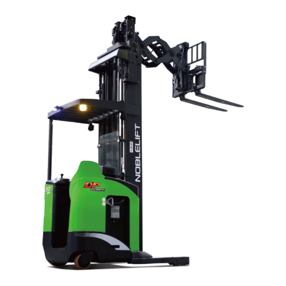
Reach Truck
RT15DP/RT15SP/RT20SP
WARNING
Do not use the reach truck before reading and
understanding these operating instructions.
NOTE:
Please check the designation of your
present type at the last page of this
document as well as on the ID-plate.
Keep it for future reference.
This truck can only be used in the factory,
tourist attractions and amusement areas.
Version 08/2023
RTXXDP/SP-SMS-001-EN
Advertisement

Related Manuals for Noblelift RT15DP


Summary of Contents for Noblelift RT15DP
- Page 1 INSTRUCTION MANUAL Reach Truck RT15DP/RT15SP/RT20SP WARNING Do not use the reach truck before reading and understanding these operating instructions. NOTE: Version 08/2023 Please check the designation of your RTXXDP/SP-SMS-001-EN present type at the last page of this document as well as on the ID-plate.
- Page 2 FOREWORD Before operating the reach truck, read this ORIGINAL INSTRUCTION MANUIAL carefully and understand the application of the truck completely. Improper operation could create danger. This manual describes the usage of different electric reach trucks. When operating and servicing the truck, make sure, that it applies to your type.
- Page 3 TABLE OF CONTENTS 1. CORRECT APPLICATION ........................3 2. TRUCK DESCRIPTION ........................... 4 a. Overview of the main components .......................4 b. Main technical data ..........................14 c. Description of the safety devices and warning labels (Europe and other, excepting USA) ....19 d.
- Page 4 1. CORRECT APPLICATION To ensure the safety of personal and equipment, drivers shall observe the following precautions: Only operator who has been trained and has the license is allowed to operate the truck; The truck is applicable for hard and flat indoors floor; Check the control and alarm devices before driving.
- Page 5 2. TRUCK DESCRIPTION Overview of the main components Fig. 1: Overview main components Seat assembly 12. Fork sideshift (right/left) control Safety pedal 13. Fork leveling assist Key switch 14. Fork reach (extend/retract) control Steering wheel 15. Fork tilt (up/down) control Instrument 16.
- Page 6 Main technical data Fig. 2: Structure schematic drawing...
- Page 7 Table 1: Main technical data for standard version Type sheet for industrial truck acc. to VDI 2198 Manufacturer’s type designation RT15DP RT15SP RT20SP Drive: electric (battery type, Battery mains, ...), diesel, petrol, fuel gas Operator type: hand, pedestrian, Standing standing, seated, order-picker...
- Page 8 Operating pressure (bar) Oil volume (l/min) Sound pressure level at driver’s seat dB(A) acc. to EN12053 Attached Table 1 RT15DP Battery acc. to DIN 43531/35/36 A, B, C, Load distance, centre of x (mm) 213/847 213/847 213/847 213/847 drive axle to fork...
- Page 9 RT15SP Battery acc. to DIN 43531/35/36 A, B, C, Load distance, centre of x (mm) 305/265 305/265 305/265 305/265 drive axle to fork Wheelbase y (mm) 1550 1550 1600 1650 4.20 Length to face of forks (mm) 1500 1500 1550 1600 Aisle width for pallets 4.33...
- Page 10 Attached Table 2 RT15DP Mast specification 4500 4920 6500 7500 8500 9500 10500 3994 4050 4240 Truck 4114 4170 4360 4480 Batter weigh y type 4249 4305 4495 4615 4735 4374 4430 4620 4740 4860 4980 5100 RT15SP Mast specification...
- Page 11 Description of the safety devices and warning labels (Europe and other, excepting USA) Warning labels: Fig. 3: Warning labels Warning label: yellow speckled reflective film, to remind the highest point of the mast. B1, B2 Trademark and company website. C1, C2, C3 Do not stand under or on the fork.
- Page 12 Safety devices: Fig. 4: Safety devices Emergency switch: Press this button immediately to cut off the power supply when the truck is out of control, and all lifting-, lowering-, traveling-, shifting-functions will be stopped. Key switch: To prevent against unauthorized access, turn the key counterclockwise and remove it. Pedal switch: Operate the truck with left foot on the foot pedal switch, the left foot and right foot must be stepped on the left and right foot pedal switches respectively when driving the truck forwards and backwards, otherwise it will be failed.
- Page 13 Location of VIN (Vehicle Identification Number) Fig. 5: Location of VIN (Vehicle Identification Number) The VIN (Vehicle Identification Number) is located on the chassis, mast and forks of the truck, and the truck equipped with hook type fork also has the corresponding serial number of the chassis on the fork. Identification plate (ID-plate) Designation, type Battery weight Min./Max in kg...
- Page 14 3. WARNINGS, RESIDUAL RISK AND SAFETY INSTRUCTIONS DO NOT Use truck in environments with explosive gas, explosive dust or acid and alkali corrosion; Use truck in the environment with poor outdoor or ground conditions; Put feet or hands under or inside the lifting mechanism; Stand in front or behind the truck while driving or lifting/lowering;...
- Page 15 4. COMMISSIONING, TRANSPORTING, DECOMMISSIONING Commissioning After receiving our new reach truck or for re-commissioning you have to do following before (firstly) operating the truck: Check if all parts are included and not damaged Mast installation (please follow the instructions to install mast); ...
- Page 16 Table 2: Chassis weight and mast weight Truck type RT15DP RT20SP RT15SP Chassis pack weight [kg] 2550 Chassis pack size [mm] 2200x1450x1650 Overhead guard pack weight [kg] Overhead guard pack size [mm] 1200x1200x1400 Lift height H3 [mm] 4500 10500 4500...
- Page 17 Lifting by crane USE DEDICATED CRANE AND LIFTING EQUIPMENT. DO NOT STAND UNDER THE SUSPENDED LOAD. DO NOT WALK INTO THE HAZARDOUS AREA DURING LIFTING. PLACE THE TRUCK ON A LEVEL GROUND. Transporting ALWAYS FASTEN THE TRUCK SECURELY WHEN TRANSPORTED ON A LORRY ...
- Page 18 5. REGULAR INSPECTION This chapter describes pre-shift checks before putting the truck into operation. Regular inspection is effective to find the malfunction or fault on this truck. Check the truck on the following points before operation. REMOVE THE LOAD FROM THE TRUCK AND LOWER THE FORKS. DO NOT USE THE TRUCK IF ANY MALFUNCTION IS FOUND.
- Page 19 6. OPERATION INSTRUCTIONS a. Overview of the control devices Fig. 10: Control devices b. Power on the truck Before operating the truck, make sure that the load is stable and will not cause poor visibility. Pull the emergency button (1), insert the key to the switch (2), and turn it clockwise to "ON" position, then step on the pedal (4) and the brake (5).
- Page 20 c. Travelling After starting the truck by turning the inserted key to “ON” position, firstly step on the pedal (4) and the brake (5), then put your hand on the operating area. Push the control handle (12) towards forks or pull the handle backwards to set the travel direction, and apply different pushing/pulling force to control the speed until the truck reaches the desired speed.
- Page 21 The white mark on the mast indicates the specific lifting limits. For instance, the truck with a load centre of gravity distance c of 600 mm and a maximum lift height h 10500 mm, the maximum capacity Q for RT15DP is 1200 kg. Fig. 11: Residual capacity diagram g.
- Page 22 j. Fork sideshift (right/left) control Press and hold the fork sideshift control (7) to the left, the fork shifts to the left. Press and hold the fork sideshift control (7) to the right, the fork shifts to the right. k. Fork tilt (up/down) control Press the fork tilt control (10) forwards, the fork tilts down.
- Page 23 (check the electrolyte specific gravity after charging). After charging, the standard specific gravity of the battery electrolyte solution is 1.28g/ml. The truck is equipped with the battery as shown below: RT15DP / RT15SP / RT20SP: 36V 600AH [360x980x785 mm (LxWxH)] 36V 700AH [410x980x785 mm (LxWxH)]...
- Page 24 Battery replacement Park the truck securely, turn off the key switch (2), press the emergency button (1), remove the battery connector (13), remove the battery compartment cover, and drag the battery along the lower guide rail out of the storage area. A pallet truck or the wood underneath may help the disassembly and installation of the battery.
- Page 25 Charging Before charging ensure that the appropriate charger is applied to charge the installed battery. Before using the charger, please fully understand the instructions of the charger instructions manual. Please follow these instructions. The room for charging must be ventilated. Park the truck at a dedicated secured area with dedicated power supply.
- Page 26 8. REGULAR MAINTENANCE Only qualified and trained personnel are allowed to maintain this truck. Remove the load from the fork and lower the fork to the lowest position before maintenance. Follow instructions in chapter 4b to lift the truck by using designated lashing or jacking equipment.
- Page 27 Test the display Check, if correct fuses are used Test the warning signal Check the contactor (s) Check the frame leakage (insulation test) Check function and mechanical wear of the accelerator Check the electrical system of the drive motor ...
- Page 28 Lubricating points Lubricate the marked points according to the maintenance checklist. The required grease specification is: DIN 51825, standard grease. Type of oil Fig. 15: Lubricating points Check and refill hydraulic oil It is recommended to fill the hydraulic oil: ...
- Page 29 Check the electrical fuses Remove the plastic cover, the location of fuses is shown in Fig. 15. Specification of the fuses is shown in Table 4. Table 4: Fuse specification Rate Qty. 500A 9pcs 2pcs Fig 16: Location of fuses...
- Page 30 9. TROUBLE SHOOTING If the truck malfunctions, follow the instructions in chapter 6. Table 5: Trouble shooting TROUBLE CAUSE MAINTENANCE Lift only the max. capacity, mentioned on the Load weight too high ID-plate Battery discharged Charge the battery Lifting fuse failure Check and eventually replace the lifting fuse Load lifting failure Hydraulic oil level too low...
- Page 31 10. WIRING/CIRCUIT DIAGRAM Electrical circuit diagram Fig. 17: Electrical circuit diagram...
- Page 32 Table 6: Description of electrical components Code Item Code Item Battery 36V 0° proximity switch Fuse 10A Traction controller Fuse 10A Pump controller Fuse 10A Steering controller Fuse 10A Valve control Fuse 10A Control handle Fuse 500A DC converter Main contactor Main contactor Reach speed limit switch Emergency awitch...
- Page 33 11. HYDRAULIC DIAGRAM Fig. 18: Hydraulic diagram...
- Page 34 12. DIAGNOSTICS AND TROUBLESHOOTING These controllers detect a wide variety of faults or error conditions. The trouble shooting list is arranged in flash code sequence, indicating the fault name, VCL name and CAN object index, including the fault type; The possible causes, setting and clearing conditions and troubleshooting methods are listed.
- Page 35 Troubleshooting chart of F4A controller (traction and pump controller) POSSIBLE CAUSES FLAS FAILT FAULT NAME FAULT ACTIONS NOTE CAUSE CODE SET/CLEAR CONDITIONS Controller Overcurrent Fault Type(s): 1. External short of phase U, V, 1 = Controller OverCurrent ShutdownMotor or W motor connections. Phase U ShutdownMainContactor 2.
- Page 36 temperature below +95°C and then Cycle KSI or Interlock, if fault is still there, Reset Controller. 1. Non-controller system drain on battery. 2. Battery resistance too high. 3. Battery disconnected while driving. 4. Blown B+ fuse or main Control Severe B+ Undervoltage No drive torque.
- Page 37 Application Setup » Max Speed Supervision menu. Motor Not Stopped Fault Type(s): 1 = The motor moved more revolutions than the parameter, Motor_ Not_Stopped_Position_Error 1. Misadjusted Motor Not setting. Stopped parameters. 2 = The motor moved faster ShutdownMotor 2. See: Programmer » than the parameter, Motor_ ShutdownMainContactor Application Setup »...
- Page 38 1. Controller is operating in an extreme environment. 2. Excessive load on vehicle. 3. Improper mounting of controller which is preventing controller cooling. 4. Controller is performance- Controller Overtemp Reduced drive torque. limited at this temperature. Control Cutback Reduced regen-braking 5.
- Page 39 Cutbacks » Overvoltage Cutback. 6. See Programmer» System Monitor menu » Controller » Capacitor Voltage. Ext 5V Supply Failure 1. External load impedance on Fault Type(s): the +5V supply (pin 16) is too 1 = 5V Supply’s voltage is low. Control Disables the 5V Supply.
- Page 40 EM Brake Driver Fault Fault Type(s): 1 = Drive short. 2 = Drive Overcurrent. 1. Open or short on driver load. 3 = Driver open/ short ShutdownEMBrake 2. Dirty connector pins at Control ShutdownThrottle controller or contactor coil. (Voltage measured high, should be low.) FullBrake 3.
- Page 41 Type 1: 1. Main contactor did not close. 2. Main contactor tips are oxidized, burned, or not making good contact. 3. An external load on the capacitor bank (B+ connection Main Contactor Did Not terminal) is preventing the Close ShutdownMotor capacitor bank from charging.
- Page 42 1. Incorrect sequence in application of KSI, Interlock, Direction, or Throttle. 2. Faulty wiring, crimps, or switches at KSI, Interlock, Direction, or Throttle. 3. Moisture in above-noted digital input switches causing Control HPD Sequencing ShutdownThrottle invalid (real) On/Off state. 4. Verify input switch status. See Programmer »...
- Page 43 Controller. Programmer » Application Setup » CAN Interface » PDO Setups. 1. Stalled motor. ShutdownMotor 2. Motor encoder failure. ShutdownEMBrake 3. Bad crimps or faulty wiring. ShutdownThrottle 4. Problems with power supply Control Stall Detected Control Mode changed for the motor encoder. to LOS (Limited 5.
- Page 44 Motor Characterization Error Fault Type(s): 1 Write to memory RAM failure 72 Temp sensor fault 73 Motor hot 74 Controller temperature cutback 76 Undervoltage cutback 77 Overvoltage cutback 78 Encoder not reading properly 79 Current Regulator Tuning out of range 80 Current Regulator Tuning out of range 81 Encoder signal seen but...
- Page 45 1. Encoder Steps parameter does not match the actual motor ShutdownMotor encoder. ShutdownMainContactor 2. Verify parameter settings: AC Control Encoder Pulse Error ShutdownEMBrake Motor Setup » Quadrature ShutdownThrottle Encoder » Encoder Steps. FullBrake 3. Motor loses IFO control, and motor increase rotation without throttle signal input.
- Page 46 torque mode. ShutdownThrottle 2. Dual drive is enabled in 2. SPMSM motor feedback FullBrake torque mode. selected the encoder. 3. Dual drive enabled on only 3. AC motor selected one controller. sine-cosine. Interlock Braking Supervision Fault Type(s): 1. During interlock braking, 1.
- Page 47 Driver 2 Fault Fault Type(s): 1. Driver short circuit 3. Driver current exceeded 1.Open or short on driver load. configured over-current limits 2.Dirty connector pins at 3. Open/short circuit (Voltage controller or contactor coil. measured high, should be 3.Bad connector crimps or faulty low) wiring.
- Page 48 5. Broken wire 6. No current of the output limit Fault types 3-5 are only checked if driver checks are enabled Driver 5 Fault Fault Type(s): 1. Driver short circuit 6. Driver current exceeded 1.Open or short on driver load. configured over-current limits 2.Dirty connector pins at 3.
- Page 49 3. Open/short circuit (Voltage 4.Driver overcurrent, as set by measured high, should be the Driver 7 Overcurrent low) parameter. 4. Open/short circuit (Voltage 5. See Programmer » Controller measured low, should be Setup » Outputs » Driver 7 » high) Driver 7 Overcurrent.
- Page 50 ANALOG 2 OUT OF RANGE Analog_ 2_Out_Of_Range See Analog 1 Out of Control See Analog 1 Out of Range. Fault Type(s): Range. 1. Above High limit. 2. Below Low limit. ANALOG 3 OUT OF RANGE Analog_ 3_Out_Of_Range See Analog 1 Out of Control See Analog 1 Out of Range.
- Page 51 Fault Type(s): 1. Above High limit. 2. Below Low limit. ANALOG 14 OUT OF RANGE Control Analog_ 14_Out_Of_Range See Analog 1 Out of See Analog 1 Out of Range. Fault Type(s): Range. 1. Above High limit. 2. Below Low limit. 1.
- Page 52 10_Out_Of_Range ANALOG 31 OUT OF RANGE Control Analog_ 31_Out_Of_Range See Analog 1 Out of See Analog 1 Out of Range. Fault Type(s): Range. 1. Above High limit. 2. Below Low limit. 1. Mistuned Dual Drive CAN parameters. Control Invalid_CAN_Port NO ACTION 2.
- Page 53 + (PWM_Input_28_Duty_ Cycle_Fault_ Tolerance). PWM Input 29 Out of Range PWM_Input_29_Out_of_Ran Fault Type(s): 1. The input is disconnected. 2. The measured input frequency is below the (PWM_Input_29_Low_ Frequency) – (PWM_ Input_29_Frequency_ Fault_ 1. This fault diagnostic Tolerance). execution cycles every 4msec. 3.
- Page 54 3 = PRIMARY_DEVICE_ STARTUP_ VALID, 4 = PRIMARY_INITIALIZE_ PARAMETERS, 5 = PRIMARY_WAIT_FOR_ FIRST_SIGNALS, 6 = PRIMARY_WAIT_FOR_ SUPERVISOR, 7 = PRIMARY_RESTORE_ PARAMETER_FAIL, PRIMARY_SUPERVISOR_ FIRST_ SIGNALS_ERROR, PRIMARY_SUPERVISOR_ STARTUP_ERROR, 10 = PRIMARY_STARTUP_ TIMER_ FAILURE, 11 = PRIMARY_WAIT_CAN_ HANDSHAKING_DONE, 12 = PRIMARY_RUNNING The associated fault diagnostic with the assigned lift-input source triggers this fault.
- Page 55 ShutdownMotor The OS (device profile, .cdev ShutdownMainContactor file) is incompatible with the Hardware Compatibility ShutdownEMBrake controller. The loaded Control Hardware_Compatibility ShutdownThrottle software (.cdev) is not FullBrake compatible with the controller ShutdownPump hardware. The associated fault diagnostic with the assigned lift-input source triggers this fault.
- Page 56 than a parameter (Hazardous_Speed) for a programmed time (Hazardous_ Throttle_ Response_ Time). IMU Failure IMU_Failure Fault Type(s): 1. SPI Communication Check if configured correctly or Failure the vehicle is moving when 2. Curtis Factory Self Test calibrating. Control Failure NO_ACTION Set: Internally set as per fault 3.
- Page 57 ShutdownMotor ShutdownMainContactor S Throttle signal comes first, op VCL HPD Fault hutdownEMBrake Controller erate in the correct order ShutdownThrottle FullBrake ShutdownMotor ShutdownMainContactor Throttle signal comes first, op VCL SRO Fault ShutdownEMBrake Controller erate in the correct order ShutdownThrottle FullBrake ShutdownMotor ShutdownMainContactor Check the display configuratio Display Config Fault...
- Page 58 ShutdownMotor ShutdownMainContactor Display Wrong 3401 Model ShutdownEMBrake Choose the right display type. ShutdownThrottle FullBrake ShutdownMotor ShutdownMainContactor Not Curtis Display ShutdownEMBrake Check the display. Controller ShutdownThrottle FullBrake ShutdownMotor ShutdownMainContactor Clear communication problems Pump Handshake Fau ShutdownEMBrake with the controller (matching, Controller ShutdownThrottle protocol, line, etc.) FullBrake...
- Page 59 FullBrake ShutdownMotor ShutdownMainContactor Display Config Fault ShutdownEMBrake Check the display. Display ShutdownThrottle FullBrake OEM Faults-OEM (PUMPCONTROLLER) POSSIBLE CAUSES FLASH FAILT CA FAULT NAME FAULT ACTIONS CODE SET/CLEAR CONDITIONS ShutdownMotor ShutdownMainContactor ShutdownEMBrake Follow the correct operation s Pump_SRO_Fault ShutdownThrottle Controller equence. FullBrake ShutdownThrottle ShutdownPump...
- Page 60 1. Runtime errors are defined ShutdownMotor using the VCL Error Module and ShutdownMainContactor VCL Error. See the System ShutdownEMBrake Information file: ShutdownThrottle • Curtis Integrated Toolkit™ » ShutdownInterlockSwitch VCL Studio » Help » System VCL Run Time Error Controller ShutdownDriver1-5 Information.
- Page 61 Undervoltage battery connections defective. 2. Excessive non-controller system drain on battery. 3. Battery disconnected while driving. 4. Blown B+ fuse or steer contactor did not close. 1. Battery or battery cable resistancetoo high for a given Severe regen current. Cycle KSI. Shutdown.
- Page 62 1. Stalled steer motor. 2. Steer motor encoder failure. Warning Motor Stalled 3. Bad crimps or faulty wiring. Cycle KSI. then 4. Problems with power supply Shutdown. of the steer motor encoder. 1. Motor phase is open. Warning 2. Bad crimps or faulty motor Motor Open Cycle KSI.
- Page 63 interlock being applied. fault output. 1. New software loaded into EEPROM memory. EEPROM CRC 2. Try using function “Restore to Cycle KSI. Shutdown. Fault Factory Defaults” to clear fault. 3. Controller defective. 1. Sin/Cos Sensor defective. Sin/Cos Hold then Sin/Cos Sensor parameters Cycle KSI.
- Page 64 1. Home switch defective. Warning Home reference 2. For 360° steering, parameter Cycle KSI. then Tolerance Fault Homing Cam Angle (deg) not Shutdown. set correctly Steer Command Command input device Hold then Cycle KSI. Supervision defective. Shutdown. Wheel Position Position feedback device Hold then Cycle KSI.
- Page 65 CE-DD-002 13. DECLARATION OF CONFORMITY (VALID FOR SALE IN EU) GB] Original CE Declaration of conformity The signatory hereby declares that the specified machine conforms to the EC Directive 2006/42/EC (Machine Directive), and 2014/30/EU (Electro-Magnetic Compatibility, EMC) including their amendments as translated into national legislation of the member countries. The signatory is individually authorized to compile the technical documents and declares that the following standards, including the normative procedures contained therein, have been applied: [D] Original EG- Konformitätserklärung Der Unterzeichner erklärt hiermit, dass die angegebene Maschine den EG-Richtlinien 2006/42/EG (Maschinenrichtlinie) und 2014/30/EU (Elektromagnetische...
- Page 66 (1) Type: XXXXXXXX (2) Serial No: YYYY (3) Year of constr.: (4) Manufacturer: Noblelift Intelligent Equipment Co., Ltd. 528 Changzhou Road, Taihu Sub-district, Changxing, 313100, PR China (5) Res : <Company name>, ponsible for compiling the technical documentation <Company Address>...
Need help?
Do you have a question about the RT15DP and is the answer not in the manual?
Questions and answers