Table of Contents
Advertisement
Instruction Manual
Electric Pallet Truck with Scale
PTE15N SC
WARNING
Do not use the pallet truck before reading
and understanding these instructions.
NOTE:
• Please check the designation of your
truck type at the last page of this
manual as well as on the ID-plate.
• Keep this manual for reference.
•
Advertisement
Table of Contents

Related Manuals for Noblelift PTE15N SC


Summary of Contents for Noblelift PTE15N SC
- Page 1 Instruction Manual Electric Pallet Truck with Scale PTE15N SC WARNING Do not use the pallet truck before reading and understanding these instructions. NOTE: • Please check the designation of your truck type at the last page of this manual as well as on the ID-plate.
- Page 3 FOREWORD Before operating the truck, read this ORIGINAL INSTRUCTION MANUAL carefully and understand the usage of the truck completely. Improper operation could create danger. This manual describes the usage of different electric pallet trucks. When you operate or maintain the truck, make sure, that it applies to your type.
-
Page 4: Table Of Contents
TABLE OF CONTENTS 1. CORRECT APPLICATION ............Tõrge! Järjehoidjat pole määratletud. 2. DESCRIPTION OF THE PALLET TRUCK ....... Tõrge! Järjehoidjat pole määratletud. a. Overview of the main components ........Tõrge! Järjehoidjat pole määratletud. b. Main technical data ............... Tõrge! Järjehoidjat pole määratletud. c. - Page 5 9. PIN-CODE PANEL ..........................22 a. Introduction ............................22 b. Main parameters ..........................22 c. Main codes and functions ......................... 23 10. BATTERY CHARGING AND REPLACEMENT .................. 23 a. Replacement ............................. 23 b. Battery indicator ..........................24 c. Charging ............................25 11.
-
Page 6: Correct Application
1. CORRECT APPLICATION It is only allowed to use this electric pallet truck according to this instruction manual. The trucks described in this manual are self-propelled electric power pallet trucks. The trucks are designed to lift, lower and transport palletized loads. A wrong usage can cause human injuries or can damage the equipment. -
Page 7: Description Of The Pallet Truck
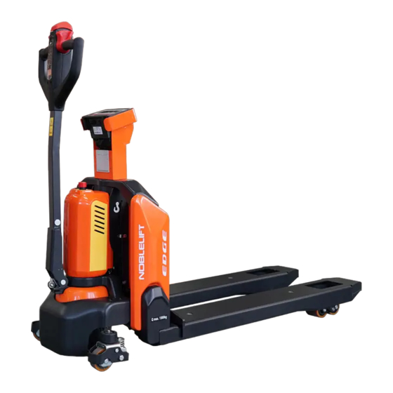
2. DESCRIPTION OF THE PALLET TRUCK Overview of the main parts Fig. 1: Overview main parts Safety (belly) button Fork Tiller Load roller Pin-code panel 10. Battery Battery discharge indicator 11. Apron Emergency button 12. Drive Unit Motor cover 13. Display Chassis 14. -
Page 8: Main Technical Data
Main technical data Fig. 2: Main technical data... - Page 9 Table 1: Main technical data for standard version Type sheet for industrial truck acc. to VDI 2198 PTE15N SC Manufacturer`s type designation Drive Battery Operator type Pedestrian Load Capacity / rated load Q (t) Load centre distance c (mm) Load distance ,centre of drive axle to fork...
-
Page 10: Description Of The Safety Devices And Warning Labels (Europe And Other, Except Usa)
Energy consumption acc. to VDI cycle kWh/h 0.19 Type of drive control DC speed Control Sound level at driver`s ear acc. to EN dB(A) <70 12053 Features weighing accuracy: +3kg for loading 1500kg Description of the safety devices and warning labels (Europe and other, excepting USA) Decal: No Passengers Decal: Crane Hook... -
Page 11: Warnings, Residual Risk And Safety Instructions
Fig. 4: Identification plate (take practicality as standard) 3. WARNINGS, RESIDUAL RISK AND SAFETY INSTRUCTIONS DO NOT • Put feet or hands under or into the lifting mechanism. • Allow other person than the operator to stand in front of or behind the truck when it is moving or lifting/lowering. -
Page 12: Commissioning, Transporting, Decommissioning
• To prevent unintended sudden movements when not operating the truck (i.e. from another person, etc.), turn off the truck. 4. COMMISSIONING, TRANSPORTING, DECOMMISSIONING Commissioning Table 2: Commissioning data Type PTE15N SC(562X1150) PTE15N SC(707X1150) Commissioning weight [kg] 180kg 185kg Dimensions [mm]... -
Page 13: Decommissioning
Fig. 6: Holes for hook Fig. 5: Lifting with a crane c. Decommissioning For storage, remove the load, lower the truck to the lowest position, grease all greasing points (regular inspection) mentioned in this manual to protect the truck against corrosion and dust. -
Page 14: Operating Instructions
• Check if all bolts and nuts are tightened firmly. • Visual check if there are any broken electric wires. • If the truck equips with a backrest, check it for damages and correct assembling. 6. OPERATING INSTRUCTIONS BEFORE OPERATING THIS TRUCK, PLEASE FOLLOW THE WARNINGS AND SAFETY INSTRUCTIONS... -
Page 15: Steering
Fig. 9: Operating direction Turn the accelerator to the desired direction forward ‘Fw.’ or backwards Bw.’ (Fig. 9). Control the travelling speed by moving the accelerator (Fig.7,13) carefully until you reach the desired speed. If you move the accelerator back to the neutral position, the controller decelerates the truck until the truck stops. -
Page 16: Malfunctions
the tiller is in the operating zone. Malfunctions If there are any malfunctions or the truck is inoperative, please stop using the truck and activate the emergency button (5) by pressing it. If possible, park the truck on a safe area and press “X” button of pin- code panel. -
Page 17: Errors
Errors Zero tare functions... -
Page 18: Summation (Total) Function
Summation (total) function... -
Page 19: Printout (Optional)
Printer (Optional) Thermal Printer Up to 65 mm/sec (max.) Printer Print speed Front side paper feed, easy to Function -10~55℃ Temperature range install paper Thermal roll, maximum diameter 85x85x54mm Paper Dimensions is 50mm, width is 58mm DC5V, DC5V-9V 8 dots/ mm, 384 dots/ line Resolution Power supply (optional) -
Page 20: Indicator Display
Paper replacement 8. Indicator display Button and Display Check Operations: With the display off, long press and hold Zero button, then press On/ Off button, the device will enter hardware check state. Release Zero button when screen shows “0 OK”. When the screen displays “0 KEY”, press Zero button, the screen shows “0 OK”;... -
Page 21: Backlight Mode Settings
Check the default unit setting when the screen displays “UNIT”. Then press Tare (Confirm) button to confirm entering into this mode. Operations: Press the Tare (Confirm) button to enter Default Unit Settings when in UNIT interface. Check the default unit at the right of the screen. Press the Gross (<—>) button to switch the unit. Press the Tare (Confirm) button again to confirm when the screen shows the desired unit. -
Page 22: Battery Replacement
Battery Replacement Storage battery: 6V/4.5A (68.5mm*46.5mm*100mm). First remove the screws of the battery cover, then replace the used batteries with the new ones. At last put back the battery cover and fix it with screws. Indicator operation panel Note: this weighing display has 5 dynamic cursors: Hold (lock cursor), ~(dynamic cursor), Net (net weight cursor), Light (backlight cursor), →0←... -
Page 23: Sensors Installation
Short press or long press one button or press two buttons at the same time to achieve different functions. Sensors Installation 1) Before the sensors installation, please make sure to power off the device head. The sensors will be in loop detection state if the device head is powered on. Operation with electricity will cause wrong data. - Page 24 Short Press - lock / unlock the weight value displayed on the current screen ; in weighing mode, press the "Hold" button on the operation panel, the current weight displayed will be locked, and the lock cursor will show at this time. If the weight is in the locked state, press the "Hold"...
-
Page 25: Pin-Code Panel
device is in "BL ON" mode, and the backlight cursor is displayed, long press to the button to turn on the backlight. Short Press – power on / power off. 2) Combined Button Function Press “lb/kg” and “Gross” button at the same time to restore factory settings (handle with care). -
Page 26: Replacement
• The batteries are lithium batteries. • Recycling of batteries undergoes national regulations. Please follow these regulations. • By handling batteries, open fire is prohibited! • In the area of battery charging neither burning materials nor burning liquids are allowed. Smoking is prohibited and the area must be ventilated. •... -
Page 27: Charging
The display can indicate a code corresponding to the type of fault, and the wrench mark is flashing at the same time. Battery State of charge The battery's state of charge indication is integrated in the LCD display; it is shown by ten notches. Each notch represent the 10% of the battery charge. -
Page 28: Regular Maintenance
Fig.12: Battery charging Table 3: Charger LED LED- signal Function Charging Green Fully charged Table 4: Charger Model Specification Input Output DZL2420SS02 24V5A (Chinese sticker) 180Vac -240Vac~2.0A MAX 29.4V 5.0A DZL2420SS02 24V5A (English sticker) 100Vac -240Vac~2.0A MAX 29.4V 5.0A DZL300SS02 24V8A (Chinese sticker) 180Vac -240Vac~3.0A MAX 29.4V 8.0A... -
Page 29: Maintenance Checklist
they should have no abnormal abrasion. Check the items emphasized in maintenance checklist. a. Maintenance checklist Table 5: Maintenance checklist Interval (Month) Hydraulic • Check the hydraulic cylinder(s), piston for damage noise and leakage Check the hydraulic joints for damage and leakage •... -
Page 30: Lubricating Points
Check the main power cable for damages • Check the start-up protection during charging • Function • Check the horn function • Check the air gap of the electromagnetic brake Test the emergency braking • Test the reverse and regenerative braking •... -
Page 31: Check Electrical Fuses
If necessary add oil till oil level reaches the filling mark. d. Check electrical fuses Fig. 14: Location of fuses Table 6: Size of the fuses Rate FU 1 FU 01 TROUBLE SHOOTING • If the truck has malfunctions follow the instructions, mentioned in chapter 6. Table 7: Trouble shooting Fault Possible cause... - Page 32 Tiller is not in the operating position Move the tiller firstly to the braking zone If the truck has malfunctions and can not be operated out of the working zone, jack the truck up and put the load handling equipment under the truck and ensure the safety of the truck. Then move the truck out of the aisle.
-
Page 33: Wiring/ Circuit Diagram
13. WIRING/ CIRCUIT DIAGRAM a. Electrical circuit diagram Without speed reduction on curves Fuse 1: 10A Fuse 01: 70A Fig.15: Electric circuit diagram (without speed reduction on curves) - Page 34 Table 8: Description of electrical components Code Item Code Item Battery CANTiller Controller Proximity Switch Pump Motor Traction Motor Pump Contactor Electromagnetic Brake Emergency button 10A Fuse Electromagnetic Valve FU01 70A Fuse Microswitch...
- Page 35 With speed reduction on curves...
-
Page 36: Hydraulic Circuit Diagram
FU1 : 10A FU01 : 70A Fig.16: Electric circuit diagram (with speed reduction on curves) Table 9: Description of electrical components Code Item Code Item Battery CAN Tiller Controller Proximity Switch Pump Motor Traction Motor Pump Contactor Electromagnetic Brake Emergency Button 10A Fuse Electromagnetic Valve Proximity Switch...
Need help?
Do you have a question about the PTE15N SC and is the answer not in the manual?
Questions and answers