Table of Contents
Advertisement
Quick Links
INSTRUCTION MANUAL
Lithium Battery Powered Reach Truck
RT16Li
WARNING
Do not use the reach truck before reading
and understanding these operating
instructions.
NOTE:
Please check the designation of your
present type at the last page of this
document as well as on the ID-plate.
Keep it for future reference.
This truck can only be used in factories,
tourist attractions, and amusement parks.
Version 08/2022
RT16Li-SMS-002-EN
Advertisement
Table of Contents
Troubleshooting

Related Manuals for Noblelift RT16Li


Summary of Contents for Noblelift RT16Li
- Page 1 INSTRUCTION MANUAL Lithium Battery Powered Reach Truck RT16Li WARNING Do not use the reach truck before reading and understanding these operating instructions. NOTE: Version 08/2022 Please check the designation of your RT16Li-SMS-002-EN present type at the last page of this document as well as on the ID-plate.
- Page 3 FOREWORD Before operating the truck, read this ORIGINAL INSTRUCTION MANUAL carefully and understand the usage of the truck completely. Improper operation could create danger. This manual describes the usage of different electric reach trucks. When operating and servicing the truck, make sure, that it applies to your type. Keep this manual for future reference.
-
Page 5: Table Of Contents
Table of Contents 1. CORRECT APPLICATION ........................4 2. DESCRIPTION OF THE REACH TRUCK ..................... 5 a. Overview of the main components ..................... 5 b. Main technical data ..........................6 c. Description of the safety devices and warning labels (Europe and other, excepting USA) ..... 10 d. -
Page 6: Correct Application
1. CORRECT APPLICATION To ensure the safety of personal and equipment, drivers shall observe the following precautions: Only drivers who have been trained and hold a industrial trucks driving license can drive this truck; This reach truck is suitable for hard and flat indoors floor conditions; Check the control and alarm devices before driving this reach truck. -
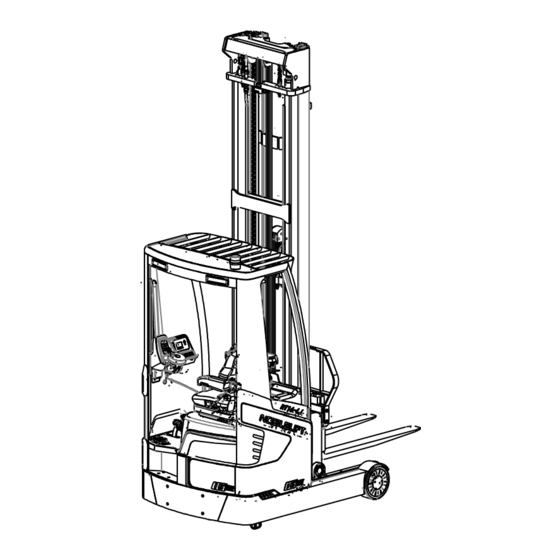
Page 7: Description Of The Reach Truck
2. DESCRIPTION OF THE REACH TRUCK Overview of the main components Fig. 1: Overview of main components Seat assembly 13. Lamp switch Accelerator pedal 14. Emergency button Brake pedal 15. Side-shift control stick (left/ right) Safety pedal switch 16. Fork tilt control stick Control unit 17. -
Page 8: Main Technical Data
Main technical data β α 2 3 8 2 3 8 a / 2 a / 2 a / 2 a / 2 Fig 2: Structure schematic drawing... - Page 9 Table 1: Main technical data for standard version Type sheet for industrial truck acc. to VDI 2198 RT16Li Manufacturer’s type designation Drive: electric (battery type, mains, ...), diesel, Battery petrol, fuel gas Operator type: hand, pedestrian, standing, seated, Seated order-picker...
- Page 10 0.48/0.4 Lowering speed, laden/ unladen 0.15/0.15 Reaching speed, laden/ unladen 10/15 Max. gradeability, laden/ unladen Hydraulic brake 5.10 Service brake Drive motor rating S2 60min 12.5 Lift motor rating at S3 15% 51.2/350 Battery voltage/ nominal capacity K (V)/(Ah) Battery weight Three-phase AC Type of drive unit Operating pressure for attachments...
- Page 11 Table of masts (RT 20Li) Lift Free lift Height, mast lowered Height, mast extended Designation 3000 2100 3910 3500 2350 4410 Two stage mast standard lift 4000 2600 4910 4500 2850 5410 4500 1563 2235 5410 5000 1730 2400 5910 5500 1897 2568...
-
Page 12: Description Of The Safety Devices And Warning Labels (Europe And Other, Excepting Usa)
设 备 代码 本车仅限 在工厂厂区、旅游景区 、游乐场所使用 工 厂 货号 诺力智 能 装备股 份有限 公司 / 浙江省 长 兴县太 湖街道 中央 大道1 8 8 8 号 RT16Li RT16Li Fig 3: Warning labels A. Crane hook label: The place for allowed crane. - Page 13 Safety device: Fig 4: Safety devices Emergency button: Please press this button immediately to cut of the power supply when the truck is out of control, all lifting-, lowering-functions will be stopped. Key switch: To prevent against unauthorized access, turn the key counterclockwise and pull it out. Brake: To stop the truck when it is driving.
-
Page 14: Identification Plate (Id-Plate)
Identification plate (ID-plate) Fig 5: Identification plate 3. WARNINGS, RESIDUAL RISK AND SAFETY INSTRUCTIONS Do not use truck in environments with explosive gas, explosive dust or acid and alkali corrosion; Do not use truck in the environment with poor outdoor or ground conditions; ... -
Page 15: Commissioning, Transporting, Decommissioning
The truck is intended to be used on hard and flat ground indoors whose roughness should be within 1cm/m The operator should hold driving license and have been trained; When operating the truck, the operator has to wear safety shoes. ... -
Page 16: Loading And Unloading/ Transportation
Table 2: Weight of truck chassis and mast Type RT16Li Truck carriage pack weight [kg] 2100 Truck carriage pack size [mm] 1800x1300X2200 Lift height H3 [mm] 5500 7500 9500 Mast pack weight [kg] 1240 1420 1600 Mast pack size [mm]... -
Page 17: Storage
Transportation DURING TRANSPORTATION ON A LORRY OR TRUCK, ALWAYS FASTEN THE TRUCK SECURELY. Lower the forks and park the truck securely. Fasten the truck according to Fig. 8, put the wood blocks under the driving cab to prevent damage to the driving wheel in transporting. Fig 8: Fixing points Storage Lower the forks to the lowest position, as shown in Figure 8, padded the cabin with sleepers to lift the... -
Page 18: Regular Inspection
5. REGULAR INSPECTION This chapter describes pre-shift checks before putting the truck into operation. Regular inspection is effective to find the malfunction or fault on this truck. Check the truck on the following points before operation. REMOVE LOAD FROM TRUCK AND LOWER THE FORKS. DO NOT USE THE TRUCK IF ANY MALFUNCTION IS FOUND. -
Page 19: Operational Instructions
6. OPERATIONAL INSTRUCTIONS a. Operational control devices Fig. 9: Operational control devices b. Power-on the truck Before operating this truck, please make sure that the load or other equipment will not cause insufficient visibility, and ensure that the load is level and placed stably. Pull the emergency button (1), insert the key switch (2), and turn it clockwise to "ON"... -
Page 20: Steering
(4) carefully until it reaches your desired speed. The speed will be slower if you release the accelerator pedal, control the speed to ensure safety. If you need abrupt deceleration, please stamp the brake pedal (5). Carefully drive the truck to the destination. Observe the route conditions and adjust the travelling speed by operating the accelerator pedal. -
Page 21: Residual Lift Diagram
[mm] for the truck with horizontal load. The white mark on the mast indicates the possible lifting limits. For instance, the truck RT16Li, with a load centre of gravity distance (c) of 600mm and a maximum lift height (h ) of 9500mm, the maximum capacity (Q) is 600 kg. -
Page 22: Fork Side-Shift (Left/ Right)
j. Fork side-shift (left/ right) Push the control stick (10) forwards, the forks shifts to the left. Pull the control stick (10) backwards, the forks shifts to the right. k. Fork tilts (up/ down) Push the tilt control stick (9) forwards, the forks tilt downward. Pull the control stick (9) backwards, the forks tilt upward. -
Page 23: Battery Changes And Replacement
7. BATTERY CHANGES AND REPLACEMENT Only qualified personnel are allowed to service or charge the batteries. Instructions of this manual and from the battery’s manufacturer must be observed. The battery type for this truck is lithium battery. Battery recycling undergoes national regulations. -
Page 24: Regular Maintenance
8. REGULAR MAINTENANCE Only qualified and trained personnel are allowed to do maintenance to this truck. Remove the load from the forks and lower the forks to the lowest position before maintenance. If you need to lift the truck, follow chapter 4b by using designated lashing or jacking equipment. - Page 25 Check the electric connections and terminals Test the Emergency switch function Check the electric drive motor for noise and damages Test the display Check, if correct fuses are used Test the warning signal Check the contactor (s) ...
-
Page 26: Lubricating Points
Lubricating points Lubricate the marked points according to the maintenance checklist. The required grease specification is: DIN 51825, standard grease. Fig 12: Lubricating points... -
Page 27: Check And Refill Hydraulic Oil
Check and refill hydraulic oil It is recommended to use the hydraulic oil: Type: H-LP 46, DIN 51524 Viscosity: 41.4 – 47 Waste material like oil, used batteries or others must be probably disposed and recycled according to the national regulations and if necessary brought to a recycling company. -
Page 28: Trouble Shooting
Table 4: Specification of the fuses Truck with Truck with Fuse Truck with F4A Fuse Fuse Inmotion 1232SE Specification Controller Specification Specification Controller Controller FU 1 FU 1 FU 1 FU 2 FU 2 FU 2 FU 3 FU 3 FU 3 FU 4 FU 4... - Page 29 The relating tiller cables are Check the tiller cables and connections. disconnected or damaged Electric system overheated Stop using and cool down the truck. Check and if necessary replace the heat Heat sensor failure sensor. The controller is damaged. Replace the controller. The truck starts up suddenly The accelerator not moves...
-
Page 30: Hydraulic Circuit Diagram
10. Hydraulic circuit diagram Fig. 15: Hydraulic circuit diagram... -
Page 31: Diagnostics And Troubleshooting, Display, And Wiring Diagram
11. DIAGNOSTICS AND TROUBLESHOOTING, DISPLAY, AND WIRING DIAGRAM These controllers detect a wide variety of faults or error conditions. Faults can be detected by the operating system or by the VCL code. This section describes the faults detected by the operating system. Diagnostics information can be obtained in either of two ways: (1) by reading the display on a hand-held or PC programmer or (2) by observing the fault codes issued by the Status LEDs. -
Page 32: Display (Truck With 1232Se Controller)
Troubleshooting The troubleshooting chart provides the following information on all the controller faults: • fault code • fault name as displayed on the programmer's LCD • the effect of the fault • possible causes of the fault • fault set conditions •... - Page 33 Fig. 16: Electrical diagram (truck with 1232SE controller)
- Page 34 Table 6: Description of electrical components (truck with 1232SE controller) Code Item Code Item Battery 51.2V/350AH Battery position monitor switch Emergency button Mast limit switch Traction motor Mast speed limit switch Pump motor Reach forward limit switch Steering motor Reach backward limit switch Traction controller Reach FW./BW.
- Page 35 1232SE controller (drive/ pump motor) troubleshooting table PROGRAMMER LCD DISPLAY CODE POSSIBLE CAUSE SET/CLEAR CONDITIONS EFFECT OF FAULT 1. External short of phase Set: Phase current exceeded Controller Overcurrent ShutdownMotor; U,V, or W motor connections. the current measurement limit. ShutdownMainContactor; 2.
- Page 36 2. Non-controller system drain Undervoltage limit with FET on battery. bridge enabled. 3. Battery resistance too high. Clear: Bring capacitor voltage 4. Battery disconnected while above Severe Undervoltage driving. limit. 5. Blown B+ fuse or main contactor did not close. Severe Overvoltage 1.
- Page 37 declared only when the Controller is performance below the Overvoltage limit. controller is running in limited at this voltage. regen. 2. Battery parameters are misadjusted. 3. Battery resistance too high for given regen current. 4. Battery disconnected while regen braking. 5.
- Page 38 disabled. Coil 1 Driver Open/Short 1. Open or short on driver Set: Driver 1 (pin 6) is either ShutdownDriver1. load. open or shorted. This fault can 2. Dirty connector pins. be set only when Main Enable 3. Bad crimps or faulty wiring. = Off.
- Page 39 ShutdownThrottle; FullBrake; ShutdownPump. Main Contactor Welded 1. Main contactor tips are Set: Just prior to the main ShutdownMotor; welded closed. contactor closing, the capacitor ShutdownEMBrake; 2. Motor phase U or V is bank voltage (B+ connection ShutdownThrottle; disconnected or open. terminal) was loaded for a FullBrake;...
- Page 40 below the fault threshold Pot2 Wiper Low 1. See Monitor menu » Inputs: Set: Pot2 wiper (pin 17) FullBrake. Pot2 Raw. voltage is lower than the low 2. Pot2 wiper voltage too low. fault threshold (can be changed with the VCL function Setup_Pot_Faults() ).
- Page 41 FullBrake; For example, if a user ShutdownPump. changes the Throttle Type this fault will appear and require cycling KSI before the vehicle can operate. OEM Faults 1. These faults can be defined (See OEM by the OEM and are 51-6 documentation.) implemented in the specific application VCL code.
- Page 42 1. Time between CAN PDO Set: Time between CAN PDO PDO Timeout PDO Timeout messages received exceeded messages received exceeded ShutdownInterlock; the PDO Timeout Period. the PDO Timeout Period. CAN NMT State set to Clear: Cycle KSI or receive Pre-operational CAN NMT message.
- Page 43 ShutdownInterlock; Clear: Download the correct ShutdownDriver1, 2, 3, 4; VCL and OS software into the ShutdownPD; controller. FullBrake; ShutdownPump. EM Brake Failed to Set 1. Vehicle movement sensed Set: After the EM Brake was ShutdownEMBrake; after the EM Brake has been commanded to set and time ShutdownThrottle.
- Page 44 ShutdownPump. Feedback Type parameters with Feedback Type=1, and Motor do not match. Technology=1 must be paired with Feedback Type=2; otherwise this fault is set. Clear: Adjust parameters to appropriate values and cycle KSI. OEM Faults CODE POSSIBLE CAUSE SET/CLEAR CONDITIONS NOTE Steering CAN Comm failure EPS CAN Communication Timeout...
- Page 45 bank (B+ connection terminal) that prevents the capacitor bank from charging. 2. Controller defective. Controller Severe Controller is operating in an Bring Warning 3 = No Undertemp extreme environment. heatsinktemp Only. action. above -35° C. Controller Severe 1. Improper mounting of Cycle KSI.
- Page 46 parameters are mis-tuned. programmed Temperature Hot. Motor Temp 1. Motor thermistor is not Motor temp Warning Sensor Fault connected properly. input within Only. Reduce 2. If the application does not the normal speed. use a motor thermistor, the operating (Max speed Motor Temperature Sensor range.
- Page 47 oxidized. 3. An external load on the capacitor bank (B+ terminal) that prevents the bank from charging. Command input device’s Command Cycle KSI. Hold then 1 = Stop. Analog1 Out of Analog 1 input (pin 8) is out of Shutdown. Range range.
- Page 48 cycle power, for safety purposes. Interlock Switch 1. When the interlock switch Interlock Interlock = 1 = Stop. Supervision inputs are a crossed Input 1 <> Off. configuration (N.O. and N.C.), Interlock the two inputs are checked. Input 3. A fault is set if Switch 1 (pin 9) =Switch 3 (pin 11).
- Page 49 1222 has halted. Shutdown. PDO2 Timeout Communication from the CAN Cycle KSI. Warning 1 = Stop. device sending the PDO2 then message to the 1222 has Shutdown. halted. PDO3 Timeout Communication from the CAN Cycle KSI. Warning 1 = Stop. device sending the PDO3 then message to the 1222 has...
-
Page 50: Display (Truck With F4A Controller)
b. Display (truck with F4A controller) Fig. 17: CURTIS-3401 Display The indications of the icons below: Battery charge is below 10% Left turn Right turn battery, lift lockout is activated. Parking Safety pedal Seat Seat belt Fault active Turtle speed mode The BDI area uses the following gauges to indicate the battery’s state of charge (0~100%). - Page 51 Fig. 18: Electrical diagram (truck with F4A controller)
- Page 52 Table 7: Description of electrical components (truck with F4A controller) Code Item Code Item Battery 48V/480AH Mast lift speed limit switch Emergency button Mast lift height limit switch Traction motor Diode Pump motor Horn Steering motor Warning signal light Traction controller Left front lamp Battery 48V/480AH Brake signal light...
- Page 53 F4A controller (pump motor) troubleshooting table FAILURE POSSIBLE CAUSES FLASH CAUSE FAULT NAME FAULT ACTIONS CODE SET/CLEAR CONDITIONS NOTE Controller Overcurrent Fault Type(s): 1 = Controller OverCurrent ShutdownMotor 1. External short of phase U, V, or Phase U ShutdownMainContactor W motor connections. 2 = Controller ShutdownEMBrake 2.
- Page 54 Clear: Bring heatsink temperature below +95° C and then Cycle KSI or Interlock, if fault is still there, Reset Controller. 1. Non-controller system drain on battery. 2. Battery resistance too high. 3. Battery disconnected while driving. Severe B+ 4. Blown B+ fuse or main No drive torque.
- Page 55 Motor Not Stopped Fault Type(s): 1 = The motor moved more revolutions than the parameter, Motor_ Not_Stopped_Position _Error setting. 2 = The motor moved faster than the 1. Misadjusted Motor Not Stopped parameter, Motor_ ShutdownMotor parameters. Not_Stopped_Speed_ ShutdownMainContactor 2. See: Programmer » Application 1-10 Error (RPM) for 160ms.
- Page 56 1. Controller is operating in an extreme environment. 2. Excessive load on vehicle. 3. Improper mounting of controller which is preventing controller cooling. Controller Overtemp Reduced drive torque. 4. Controller is performance- Cutback Reduced regen-braking limited at this temperature. Controller torque.
- Page 57 Monitor menu » Controller » Capacitor Voltage. Ext 5V Supply Failure 1. External load impedance on the Fault Type(s): +5V supply (pin 16) is too low. 1 = 5V Supply’s Disables the 5V Supply. 2. See the System Monitor » Controller voltage is out- of-range Outputs menu: External_5V_...
- Page 58 2 = Drive Overcurrent. 3. Bad connector crimps or faulty 3 = Driver open/ short wiring. (Voltage measured high, should be low.) 4 = Drive open/ short (Voltage measured low, should be high.) 5 = Wiring disabled. The assigned driver Load Hold Diver Fault Same as Driver 1 Fault Controller...
- Page 59 1. Main contactor opened during operation (while commanded closed). 2. Driver wiring to contactor’s coil (e.g., pin wiring) removed during operation. 3. Contactor/coil defective. 1. Throttle voltage exceeded the Analog Low or Analog High Throttle Input parameters for the analog input Fault Type(s): * defined for the throttle input.
- Page 60 forward and reverse, and interlock inputs have not been returned to neutral. Incorrect lifting/lowering throttle Pump HPD input condition (>25%) Fault Type(s): Parameters setting errors: 1. Only lifting ShutdownPump Controller 1. Hydraulic suppression type 2. Only lowering 2. HPD/SRO judgment time 3.
- Page 61 FullBrake match. OS General ShutdownAll Clear: Reset Controller. Controller Set: Time between CAN 1. The time between CAN PDO PDO messages received messages received exceeded the exceeded the PDO PDO Timeout Period as defined PDO Timeout Timeout Period. by the Event Timer parameter. Controller Clear: Receive CAN 2.
- Page 62 FullBrake Motor Characterization Error Fault Type(s): 1 Write to memory RAM failure 72 Temp sensor fault 73 Motor hot 74 Controller temperature cutback 76 Undervoltage cutback 77 Overvoltage cutback 78 Encoder not reading properly 79 Current Regulator Tuning out of range 80 Current Regulator Tuning out of range 81 Encoder signal...
-
Page 63: Display (Truck With Inmotion Controller)
controller temp cutback 106 PMAC motor controller Undervoltage cutback 107 PMAC motor controller overvoltage cutback 1. Encoder Steps parameter does not match the actual motor ShutdownMotor encoder. ShutdownMainContactor 2. Verify parameter settings: AC Encoder Pulse Error ShutdownEMBrake Motor Setup » Quadrature Controller ShutdownThrottle Encoder »... - Page 64 Fig. 19: Inmotion display Turtle Speed Symbol: Lights up when the truck is running in Slow (Turtle) Speed Mode. Wrench Symbol: Lights up when the truck is in neutral. Battery Symbol: Lights up when the battery charge is lower than or equal to 20%. Lift Lock Symbol: Lights up when the battery charge is lower than or equal to 10%.
- Page 65 Fig. 20: Electrical diagram (truck with Inmotion controller)
- Page 66 Table 8: Description of electrical components (truck with Inmotion controller) Code Item Code Item Battery 48V/480AH Turn signal switch Emergency button Horn Traction motor Buzzer Pump motor FU1/FU2 10A fuse Steering motor FU01/FU02 250A fuse Traction controller FU03 30A fuse Display Warning signal light Left front lamp...
- Page 67 Inmotion controller troubleshooting table FAULT FAULT DISPLAYED ON SCREEN CLEAR CONDITIONS CODE ERROR Incorrect start Release pedal switch Accelerator pedal switch active before key on ERROR Incorrect start Turn off the direction switch Accelerator pedal switch active before key on ERROR Forward switch and reverse switch active at Direction switch fault...
- Page 68 ERROR Incorrect start Reset tilt switch Tilt switch active before key on ERROR Incorrect start Reset side switch Side switch active before key on ERROR Incorrect start Reset attachment switch Attachment switch active before key on ERROR Incorrect start Reset lift switch Lift switch active before key on ERROR Incorrect start...
- Page 69 WARNING [ refer to the inspection method when ACS Traction motor temperature is low controller reports 86 fault] 1. Compare whether the monitoring temperature of the controller is significantly different from the actual temperature; 2. Check the wiring from the controller to the motor temperature sensor for open circuit or poor insulation;...
- Page 70 1. Measure the battery voltage; WARNING 2. Check the cable for looseness poor DC bus voltage of traction controller is low insulation. WARNING For protection after refreshing the program, The default value of the traction controller is restart the key. updated Low battery power, low voltage, motor over temperature or controller over temperature, and...
- Page 71 1. Compare whether the monitored temperature of the controller is significantly different from the actual temperature; 2. Check the wiring from the controller to the motor temperature sensor for open circuit or poor insulation; 3. Measure whether the resistance value of the ERROR motor temperature...
- Page 72 1. Check whether the wiring from the accelerator to the controller has poor insulation, unplug the accelerator plug- in, and test whether there is still code 114 (if yes, go to the next step, if not, it is accelerator fault); 2.
- Page 73 1. Compare whether the monitoring temperature of the controller is significantly different from the actual temperature; 2. Check the wiring from the controller to the motor temperature sensor for open circuit or WARNING poor insulation; Pump motor temperature is low 3.
- Page 74 1. Check the wiring from motor encoder to controller for open circuit or poor insulation; 2. Check whether the encoder is installed in ERROR place or installed in the opposite direction; Pump controller encoder fault 3. Replace the encoder (for the newly replaced encoder, confirm whether the wiring definition is consistent with the original encoder);...
- Page 75 1. Measure whether there is battery voltage on the 28 pin line of the controller ( it is necessary to turn on the key switch for measurement); 2. Measure whether the insulation of line 29/ 4/ ERROR 16/ 24/ 25 is good; Open drain of pump output open or short 3.
- Page 76 1. Check whether the wiring from the accelerator to the controller has poor insulation, unplug the accelerator plug- in, and test whether there is still code 114 (if yes, go to the next step, if not, it is accelerator fault); 2.
- Page 77 1. Compare whether the monitoring temperature of the controller is significantly different from the actual temperature; 2. Check whether sufficient silicone grease is applied between controller ERROR electric control aluminum plate and between the Steer controller temperature is high cutback electric control aluminum plate and the truck;...
- Page 78 ERROR 1. Measure the battery voltage; DC bus voltage of steer controller is high 2. Check the cable for looseness poor cutback insulation. There is a large difference between the output of the steering wheel sensor and the output pulse ERROR number of the steering motor.
- Page 79 1. Compare whether the monitoring temperature of the controller is significantly different from the actual temperature; 2. Check the wiring from the controller to the motor temperature sensor for open circuit or WARNING poor insulation; Steer motor temperature is low 3.
- Page 80 1. Measure the battery voltage; WARNING 2. Check the cable for looseness poor DC bus voltage of steer controller is high insulation. 1. Measure the battery voltage; WARNING 2. Check the cable for looseness poor DC bus voltage of steer controller is low insulation.
-
Page 81: Declaration Of Conformity (Valid For Sale In The Eu)
CE-DD-002 12. Declaration of Conformity (valid for sale in the EU) [GB] CE Declaration of Conformity The signatory hereby declares that the specified machine conforms to the EU Directive 2006/42/EC (Machine Directive) and 2014/30/EU (Electro-Magnetic Compatibility, EMC) including their amendments as translated into national legislation of the member countries. The signatory is individually authorized to compile the technical documents. - Page 82 og 2014/30/EU (elektromagnetisk fordraglighet - EMV) inklusiv disses endringer og den tilsvarende rettsforordning til omsetning av nasjonal rett. Hver undertegnede er fullmektig til å sette sammen de tekniske dokumentene. [PL] DEKLARACJA ZGODNOŚCI WE Niżej podpisani deklarują, że poniżej opisana maszyna spełnia wymagania określone w dyrektywach Europejskich 2006/42/EC (Dyrektywa Maszynowa) i 2014/30/EU (Kompatybilności elektromagnetycznej - EMC) wraz z ich późniejszymi zmianami oraz odpowiednimi rozporządzeniami mającymi na celu przeniesienie tych dyrektyw do prawa krajów członkowskich.
Need help?
Do you have a question about the RT16Li and is the answer not in the manual?
Questions and answers