Table of Contents
Advertisement
Quick Links
Service & Maintenance Manual
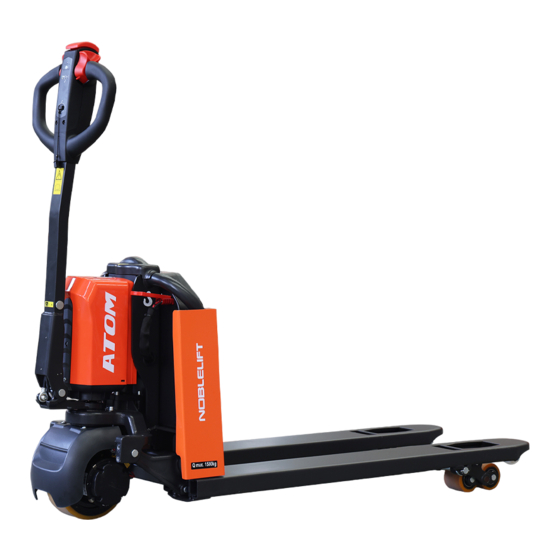
Electric Pallet Truck
PTE15Q
WARNING
Do not use the pallet truck before reading and
understanding these operating instructions.
NOTE:
Please check the designations of your present
type at the last page of this document as well
as on the ID-plate.
Keep for future reference.
Tell:4008-836115
Version 01/2022
Advertisement
Table of Contents

Related Manuals for Noblelift PTE15Q


Summary of Contents for Noblelift PTE15Q
- Page 1 Tell:4008-836115 Service & Maintenance Manual Electric Pallet Truck PTE15Q WARNING Do not use the pallet truck before reading and understanding these operating instructions. NOTE: Please check the designations of your present Version 01/2022 type at the last page of this document as well as on the ID-plate.
-
Page 2: Table Of Contents
TABLE OF CONTENTS REGULAR MAINTENANCE ....................... 2 Maintenance checklist........................2 Lubrication points ..........................4 Check and refill hydraulic oil ......................4 Check electrical fuses ........................5 TROUBLE SHOOTING ........................6 Common trouble shooting ....................... 6 Fault code ............................6 WIRING/CIRCUIT DIAGRAM ......................9 Electrical circuit diagram ......................... - Page 3 Parameter setting .......................... 34 Parameter monitoring ........................35 Fault information ........................... 36 System Settings ..........................37 Mechanical dimensions ........................ 38...
-
Page 4: Regular Maintenance
1. REGULAR MAINTENANCE a. Maintenance checklist Safety button / Belly button Tiller Magnetic lock Discharge indicator and charging indicating LED Emergence button Hydraulic unit cover chassis Load roller 10. Battery 11. Apron 12. Driving unit 13. Side roller (option) - Page 5 Maintenance checklist Interval(Month) 3 6 12 Hydraulic Check the hydraulic cylinder(s), piston for damage noise and leakage Check the hydraulic joints for damage and leakage Inspect the hydraulic oil level, refill if necessary Refill the hydraulic oil ( 12 month or 1500 working hours) ...
-
Page 6: Lubrication Points
33 Check the air gap of the electromagnetic brake 34 Test the emergency braking 35 Test the reverse and regenerative braking 36 Test the safety (belly) button function 37 Check the steering function 38 Check the lifting and lowering function ... -
Page 7: Check Electrical Fuses
Waste material like oil, used batteries or other must be probably disposed and recycled according to the national regulations and if necessary brought to a recycling company. The oil level height shall be in the not lifted position min. 0.3L to 0.5L. If necessarily add oil at the filling point. -
Page 8: Trouble Shooting
2. TROUBLE SHOOTING a. Common trouble shooting Table 3: Trouble shooting TROUBLE CAUSE REPAIR Lift only the max. capacity, mentioned Load weight too high on the ID-plate Battery discharged Charge the battery Check and eventually replace the Lifting fuse faulty Load can’t be lifted lifting fuse Check and eventually refill hydraulic... - Page 9 Fault code Fault name Fault description Solution Fault source Number displayed on handle The interlock switch is closed in the upright driving mode. If the upright driving switch (tortoise speed switch) is released, the fault has not been the interlock switch is closed when upright driving cleared after resetting the interlock: BM24C10-CAN controller (UpRight_Fault)
- Page 10 2. If the internal temperature sensor of the battery fails, replace the battery; temperature inside the battery. reserve reserve BM24C10-CAN controller Motor_Temp_Fault reserve The lifting switch is closed before opening BM24C10-CAN controller PumpSRO_Fault reserve System task failure reserve BM24C10-CAN controller PTE15Q Fault code...
-
Page 11: Wiring/Circuit Diagram
3. WIRING/CIRCUIT DIAGRAM a. Electrical circuit diagram PTE15Q Table 4: Description of electrical diagram Code. Item Code Item Battery CAN tiller Controller Proximity switch Pump motor Traction motor Pump contactor Electromagnetic brake Emergency button 10A fuse Electromagnetic valve FU01 70A fuse... -
Page 12: Hydraulic Circuit
Micro switch b. Hydraulic circuit Lifting cylinder Lowering valve Throttle valve Pressure control valve Hydraulic power unit Oil tank Table 5: Hydraulic oil inspection Degree of purity Smell Status Result Clear and same color as before Good Good Can be used Transparent Good Mixed with other oil... -
Page 13: Maintenance Of Main Components
4. MAINTENANCE OF MAIN COMPONENTS Battery replacement Unplug the plug, flip the switch outward to remove the battery. Battery and charger 1. 8A&12A... -
Page 14: Battery Introduction
2. Battery introduction Outer-appearance parts 1.Remove the Electronically controlled cover and unscrew 4 screws to remove the cover. - Page 15 2.Driving wheel cover There are 2 fixed screws in the small cover. There are 4 fixed screws in the small cover.
-
Page 16: Tiller
Tiller 1.Remove the two fixed screws to open the rear cover. Remove the internal wiring harness and remove the handle. 2.Disassembly of air spring Remove the screw with Remove circlip Remove the axle. Remove the circlip and 5mm Allen wrench. with circlip plier. -
Page 17: Disassembly Of Cylinder
3.Assembly of air spring Put the air spring into Insert the axle. Make hole of axle and Support the air spring the tiller arm. hole of screw on the with flat metal tool to fix same level with Allen the screw. wrench. - Page 18 Pull out the protective Disconnect the cylinder cover from top. from pump with 5mm Allen wrench. During assembly, it’s required to apply thread locker with 1243 model. For PTE15Q, there is a O ring on the valve. Please keep it.
-
Page 19: Pump Disassemble From Machine
Pump disassemble from machine Remove the left screw Remove the right screw Remove the top screw Put a wooden block with 5mm Allen wrench. with 5mm Allen wrench. with 5mm Allen wrench. under the chassis. Power on the truck, Turn over the cylinder. Disconnect the cylinder After disconnection, activate the lowering... -
Page 20: Disassembly Of Driving Unit
Disassembly of driving unit Remove the screw with 6mm Remove 4 screws with 6mm Remove the driving unit from Allen wrench. It’s required to Allen wrench. the chassis. apply thread locker with 1243 model. Pad the hole in the middle First remove the bearing, then Remove the screw with 5mm with an iron sheet or other... -
Page 21: Disassembly Of Brake
Disassembly of brake Remove the plastic cover Remove three screws with before replacement of brake, 4mm Allen wrench to take it’s connected with glue out the brake. Driving wheel Cut the plastic strip then Remove 10 screws with 5mm disconnect the plug. Allen wrench, take out the wheel ring. -
Page 22: Disassembly Of Emergency Button
J. Disassembly of emergency button Remove the cable Remove two screws Remove the screws on Remove the cable clamp with on the right side of the the left side of the clamp. Make sure screwdriver. frame with 5mm Allen frame with 5mm Allen during assembly of the wrench. -
Page 23: Disassembly Of Controller
K. Disassembly of controller PTE15Q It’s recommended to Remove the plugs. Remove two screws with make picture for 5mm Allen wrench to take routing and connection out the controller. before controller is disconnected. Four plugs here from top to bottom... -
Page 24: Disassembly Of Chassis
M. Disassembly of chassis Remove the elastic pin Remove the circlip First remove four to take out the axle, then disconnect rock arm elastic pins. Note: disconnect rock arm from body. elastic pin specification from chassis. is 6*40.5*30. Note: elastic specification is 6*40. -
Page 25: Pump Motor
N. Pump motor Remove cable terminals from the There are four carbon motor with 10mm wrench, and then brushes after motor cover is remove two screws on top of the removed. Every two are motor with 10mm wrench to take welded to the positive and out the motor. - Page 26 avoid vehicle and personal safety accidents. The hand-held unit will automatically save the modification parameters, just need to close the key switch and restart. The CURTIS handheld unit can be connected in the event of a controller power or power failure The process of reading fault code After connecting the handheld unit with the controller, open the key switch From the menu list of CURTIS handheld units, find: Faults...
- Page 27 The Curtis 1313 handheld programmer is used to configure Curtis motor control systems. With the programmer, you can adjust and save parameter settings, monitor real-time data, and perform diagnostics and troubleshooting. Warning: The control system can affect the vehicle's acceleration rate, deceleration rate, hydraulic system and braking.
- Page 28 Connect the handheld programmer into the control system by plugging it into the controller’s charger/programmer port. The programmer automatically powers up, and displays this screen while it loads information from the controller.
- Page 29 Softkeys These three keys are blank, because their function is context-specific. At any given time, their function is shown directly above them on the LCD screen. The symbol “»” indicates more options; pressing the soft key under the “»” will scroll to another set of options. Arrow keys With these four keys you can scroll up and down and right and left, within the display.
- Page 30 The nine menus DIAGNOSTICS MENU In the Main Menu, highlight the Diagnostics icon and press the “Select” soft key to go to the Diagnostics menu. You can return to the Main Menu at any time by pressing the Main Menu key ( ). The Diagnostics menu contains two folders: Present Errors and Fault History.
- Page 31 Fault History folder This folder lists all the faults encountered since the Fault History was last cleared. You can clear the entire contents of this folder to allow a fresh Fault History to be started. “Clear All” is used to empty the Fault History folder.
-
Page 32: Handheld Unit With Electric Control Of Jiachen
6. Handheld Unit with Electric Control of Jiachen Function introduction Function description The Handheld Unit is a powerful and intuitive programming and diagnostic tool that can monitor and modify controller parameters online, allows users to save parameter files online, saves the parameter files to the Handheld Unit or an external USB storage device, and sends the edited parameter files to the motor controller when online. -
Page 33: Technical Parameters
Direct access to controller parameters and can be modified; Technical parameters parameter value unit Rated operational voltage 12~96 ℃ Rated operational voltage -20~70 ℃ Storage temperature -40~85 Working humidity 95% RH max Degree of protection IP51 on the front, IP40 on the back Interface pin definition The external power supply and communication interface of the Handheld Unit adopts the RJ45 network port, which is connected to the electric control through a spiral adapter cable, and the... -
Page 34: Button
The interface pin definition: Pin number Description Pin number Description CAN_L / RS232_RX CAN_H / RS232_TX Button The Handheld Unit uses silicone buttons, a total of 13 buttons, which are up, down, left, right, increase, decrease, F1~F3 function buttons, power button, favorites button, home button, and help button. -
Page 35: Function Description
2) After the Handheld Unit is turned off, press the power button for 1 second, and it will restart to run. Home button: Press this button in the main interface to cycle through various applications. Press the main interface key in other interfaces to return to the main interface display. Function description 1. -
Page 36: System Information
Set the current backlight brightness, System settings communication mode, and USB mode; 2.System Information Select the "SysInfo" function icon in the main interface and press the "F3" key to enter the system information viewing sub-interface; this interface displays the product serial number, hardware version number, and software version number. -
Page 37: Parameter Monitoring
After entering the parameter modification interface, as shown in the lower left corner of picture, use the “± key“ to modify the parameter value. Each time you press it, the parameter will increase or decrease by 1; if you increase or decrease by 10 each time, you can press the function key “F1“... -
Page 38: Fault Information
R. Fault information Select the "ErrorInfo" function icon on the main interface, You can view the current faults and historical faults of the controller. Error information interface... -
Page 39: System Settings
S. System Settings Select the "SysSet" function icon in the main interface to set the current backlight brightness, communication mode (RS232 or CAN), USB mode and system language and other local settings. a) Backlight brightness: adjust between 10~100, press the corresponding "+" and "-" keys, the value will increase or decrease correspondingly;... -
Page 40: Mechanical Dimensions
T. Mechanical dimensions Unit: mm...
Need help?
Do you have a question about the PTE15Q and is the answer not in the manual?
Questions and answers