
Related Manuals for Noblelift EPT15


Summary of Contents for Noblelift EPT15
- Page 1 SERVICE & MAINTENANCE MANUAL Electric Pallet Truck Version 12/2012 EPT -SHFW-001 https://forklift-manuals.jimdofree.com...
-
Page 2: Table Of Contents
CONTENT FOREWORD .............................. 3 GENERAL ............................4 1.1 INTRODUCTION – MAINTENANCE SAFETY PRECAUTIONS ..........4 1.2 MEASUREMENT CONVERSIONS ................... 8 SPECIFICATION ..........................13 2.1 LOCATION OF COMPONENTS ....................13 SPECIFICATION SHEETS ....................14 2.2.1 TECHNICAL FEATURES ..................... 14 LUBRICATION ........................17 ELECTRIC SYSTEM ........................ -
Page 3: Foreword
FOREWORD Proper operation, maintenance, troubleshooting and repairs are necessary to preserve the performance of the pallet truck over a long period and ensure that fault and breakdowns do not occur. The purpose of this service manual is to provide necessary information especially in inspections, repair and maintenance. -
Page 4: General
1. GENERAL 1.1 INTRODUCTION – MAINTENANCE SAFETY PRECAUTIONS Maintenance work may cause injuries. Always take care to perform work safe, at least observing the following. It is of utmost importance that maintenance personnel pay strict attention to these warnings and precautions to avoid possible injury to themselves, others or damage to the equipment. A maintenance program must be followed to ensure that the machine is safe to operate. - Page 5 It should be noted that the machines hydraulic systems operate at extremely high potentially dangerous pressures. Every effort should be made to relieve any system pressure prior to disconnecting or removing any portion of the system. Relieve system pressure by cycling the applicable control several times with the engine(motor) stopped and ignition on, to direct any line pressure back into the reservoir.
- Page 6 Always use the grades of grease and oil recommended by NOBLELIFT choose the viscosity specified for the ambient temperature. Exhaust gas is dangerous provide ventilation when working in a closed space. Avoid breathing dust that may be generated when handling components containing asbestos fibers.
- Page 7 When changing the oil or fitter, check the drained oil and filter for any signs of excessive metal particles or other foreign materials. Always use NOBLELIFT genuine parts for replacement. ENSURE REPLACEMENT PARTS OR COMPONENTS ARE IDENTICAL OR EQUIVALENT TO ORIGINAL PARTS OR COMPONENTS. ...
-
Page 8: Measurement Conversions
1.2 MEASUREMENT CONVERSIONS Length Unit mile 0.01 0.00001 0.3937 0.03281 0.01094 0.000006 0.001 39.37 3.2808 1.0936 0.00062 100000 1000 39370.7 3280.8 1093.6 0.62137 2.54 0.0254 0.000025 0.08333 0.02777 0.000015 30.48 0.3048 0.000304 0.3333 0.000189 91.44 0.9144 0.000914 0.000568 mile 160930 1609.3 1.6093 63360... - Page 9 Pressure Unit kgf/cm Pa=N/m lbf/in lbf/ft kgf/cm 0.98067 98066.5 98.0665 14.2233 2048.16 1.01972 100000 14.5037 2088.6 Pa=N/m 0.00001 0.001 0.001 0.00015 0.02086 0.01020 0.01 1000 0.14504 20.886 lbf/in 0.07032 0.0689 6894.76 6.89476 lbf/ft 0.00047 0.00047 47.88028 0.04788 0.00694 kgf/cm =735.56 Torr(mmHg)=0.96784atm Standard tightening torque The following charts give the standard tightening torques of bolts and nuts.
- Page 10 INCH TABLE 4T, 5T Classification Bolt type Bolt size Torque kgf · m (lbf · ft) Torque kgf · m (lbf · ft) 0.6 ± 0.06 1.7 ± 0.2 5/16 1.2 ± 0.12 3.0 ± 0.3 2.0 ± 0.20 5.6 ± 0.5 7/16 3.2 ±...
- Page 11 O – ring Plug PF THREAD Thread Torque (kgf·m) 1.1 ± 0.1 2.6 ± 0.2 4.6 ± 0.3 8.5 ± 0.4 19 ± 1.0 33 ± 2.0 TORQUE FOR SWIVEL NUT WITH O-RING Connector O – ring Swivel – nut hose Tube O.D (inch) Thread (in)
- Page 12 APPROXIMATE CONVERSIONS Conv Non–SI Conv Unit Factor Unit Factor Unit Torque × 8.9 × 0.113 Newton meter (N·m) = ln·in = N·m × 0.74 × 1.36 Newton meter (N·m) = lb·ft. = N·m × 0.102 × 7.22 Newton meter (N·m) = kg·m = lb·ft.* Pressure (Pa = N/m...
-
Page 13: Specification
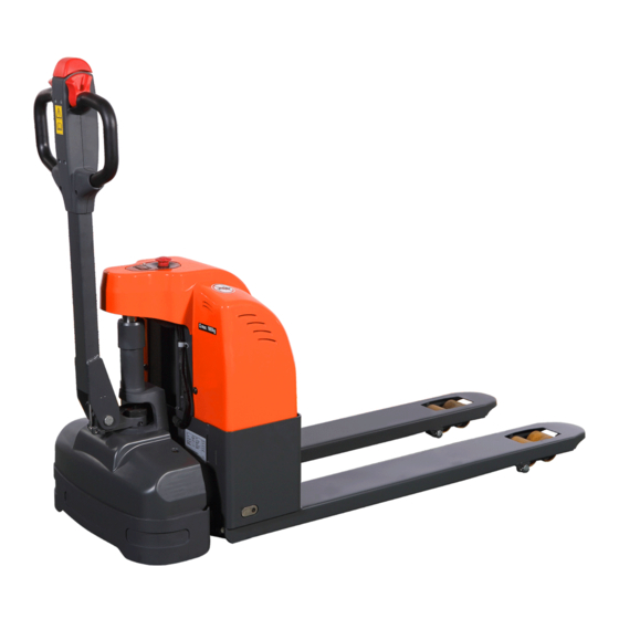
2. SPECIFICATION 2.1 LOCATION OF COMPONENTS Multifunction tiller Drive motor cover Discharge indicator and charging Lift Cylinder indicating LED Emergency Button Drive wheel Main cover Castors Fork chassis Safety (belly) button Load Wheels Drive control switch Charging cable https://forklift-manuals.jimdofree.com... - Page 14 CONTROL HANDLE Safety (belly) button Lifting button Drive control switch Lowing button Horn button https://forklift-manuals.jimdofree.com...
-
Page 15: Specification Sheets
2.2 SPECIFICATION SHEET 2.2.1 Technical Features Type sheet for industrial truck acc. to VDI 2198 EPT15 Manufacturer`s type designation Drive electric Operator type pedestrian Q (t) Load Capacity / rated load c (mm) Load centre distance x (mm) Load distance ,centre of drive axle to fork... - Page 16 https://forklift-manuals.jimdofree.com...
- Page 17 2.3 LUBRICATION Hydraulic oil Hydraulic oil must have anti-wear qualities at least. It is not advisable to mix oils of different brands or types, as the may not contain the same required additives or be of comparable viscosities. Name: Thickened hydraulic oil. ISO Viscosity Grade Characteristics unit...
-
Page 18: Electric System
ELECTRIC SYSTEM 3.1 ELECTRIC DIAGRAM WIRING DIAGRAM Electric diagram EPT 15 Fuses EPT 15 FU1 : FU2 : 0.5A FU01 : 60A FU02 : 60A https://forklift-manuals.jimdofree.com... - Page 19 Code Description Qty. Battery, 12V/64Ah Emergency button ,S100/80 FU01,FU02 Fuse, 60A Motor for traction, DC24V Motor for lift, DC24V Brake, DC24V Controller, Curtis 1212-2501 Fuse,10A Battery Indicator, CURTIS 906 T24BNBO Trouble light Buzzer, HYD-4216W 24VDC diode,1N5408 Contactor for lift Micro switch ,WS1-Z5-W200R200 Valve, DC24V Inductive Sensor, NBN5-FT-E2 Charger, 24V/8A...
- Page 20 CONNECTION DIAGRAM https://forklift-manuals.jimdofree.com...
- Page 21 CABLE SYSTEM Description Qty. Handle control cable Control cable Drive motor power cable https://forklift-manuals.jimdofree.com...
-
Page 22: Electrical Installation
3.2 ELECTRICAL INSTALLATION Handle Emergency button ,S100/80 Fuse, 60A Inductive sensor, NBN5-FT-E2 8. Electrical installation board Relay,ARP12F-1C 24VDC Micro switch , Charger, 24V/8A Buzzer, HYD-4216W 24VDC WS1-Z5-W200R200 Motor for traction Charging indicator Protection module ,BD-W-115 Battery indicator, CURTIS 906 Power cord Controller, Curtis 1212-2501 T24BNBO Key switch... -
Page 23: Drive Wheel
REB-05-06 Rate voltage DC 24V Output Torque 6N.M Gear Box transmission ratio 1:28 3.4 PUMP STATION Type: CMB3-VB1111131-030 Item EPT15 Rated voltage Rated output 0.8kw R.P.M 4200 rpm Rated current 60 A Rated hour 1.8 min. Insulation class F class... - Page 24 20A DURATION OF DISCHARGING CURVE (ENVIRONMENTAL TEMPERATURE = 25 Discharging (min) 100% DURATION OF DISCHARGING LIFE TEST CURVE ( ENVIRONMENTAL TEMPERATURE = 25 Circle (time) CHARGING CURVE Voltage (V) Current (A) Time (h) https://forklift-manuals.jimdofree.com...
-
Page 25: Charger
3.6 CHARGER Type: QQE192-8CH17-26B for EPT MAIN PRODUCT SPECIFICATION Output current Max. output power battery capacity Input voltage Output voltage range 240W 40AH-100AH 230Vac +28.2Vdc 150W 25AH-60AH 115/230Vac +29.4Vdc ENVIRONMENTAL CONDITION Item Technical specification Unit Remark Humidity 5%-95% With package ≦3000 Altitude Work normally... - Page 26 ELECTRICAL CHARACTERISTICS Input characteristics Item Technical specification Unit Remark Rated input voltage Input voltage range 180-264 230Vac input voltage 47—63 frequency 264Vac input / start-up cold condition ≤100 Inrush current /environmental temperature is 25℃ Max input current Vin=180Vac, rated load When input is on,voltage for fan is 12V When input voltage is off,there is no output Fan function voltage for fan...
- Page 27 INPUT TERMINAL DIAGRAM & DEFINITION OUTPUT TERMINAL DIAGRAM & DEFINITION LED CONNECTOR DIAGRAM & DEFINITION FAN CONNECTOR DIAGRAM&DEFINITION RELAY CONNECTOR DIAGRAM & DEFINITION https://forklift-manuals.jimdofree.com...
-
Page 28: Curtis Controller 1212
3.7 CURTIS CONTROLLER 1212 https://forklift-manuals.jimdofree.com... - Page 29 CONNECTIONS Low Current Connections A 14-pin Molex low current connector in the controller provides the low current logic control connections: The mating connector is a Molex Mini-Fit Jr., receptacle p/n 39-01-2140 with appropriate 45750-series crimp terminals. A 4-pin low power connector is provided for the programmer and the battery charger.
- Page 30 Connections (B+, B-) have one terminal each. STANDARD_PARAMETER Parameter standard RANGE Unit DESCRIPTION Software parameter Drive menu Sets the rate (in seconds) at which the speed command increases when throttle is applied with the speed limit Accel Max Speed 0.2 to5.0 seconds pot is in its maximum speed position, and the vehicle is traveling forward.
- Page 31 Sets the rate (in seconds) that is used to slow down the vehicle during emergency reverse, i.e., when a throttle command >80% in the reverse direction is E Stop Decel 0.2 to 4.0 seconds given while the vehicle is moving forward. This gives the operator a way to stop more quickly when unexpected conditions arise.
- Page 32 Throttle menu he 1212 controller can accept inputs from both 5kΩ, 3-wire pot throttles and voltage throttles. Set the throttle type parameter to match the throttle used in your application. 5kΩ, 3-wire pot throttles 0 = wigwag 1 = inverted wigwag 2 = single-ended;...
- Page 33 Sets the maximum current the controller will supply to the motor during 15–90 A normal driving. By limiting the current supplied, this parameter can be used to Main Current Limit 15 to 90 Ampere protect the motor from potentially damaging currents or to reduce the maximum torque applied to the drive system.
- Page 34 Sets the system resistance (motor + brushes + wiring + connections) used for load compensation and System Resistance 0 to 800 mOhms speed estimation. Control system performance depends on this parameter being set correctly; it must be set to the actual cold motor resistance. Resistance is automatically measured under a preset low current before the brake is released.
- Page 35 Sets the battery charge level at which Lift locklock Liftlock Threshold 0 to 50 protection begins Compensation menu Sets the motor load compensation. Higher values IR Comp 0 to 90 provide stronger disturbance rejection, while lower values provide smoother operation. Sets the motor load compensation after the throttle is released to neutral and the speed is estimated to be Anti Rollback Comp...
- Page 36 TROUBLESHOOTING CHART The 1212 controller provides diagnostics information to assist technicians in troubleshooting drive system problems. The diagnostics information can be obtained in two ways: by reading the appropriate display on the handheld programmer or by observing the fault codes issued by the status LED. PROGRAMMER DIAGNOSTICS The handheld programmer presents complete diagnostic information in plain language.
- Page 37 https://forklift-manuals.jimdofree.com...
- Page 38 CURTIS 1311 HANDHELD PROGRAMMER Curtis programmers provide programming, diagnostic, and test capabilities for 1212 controllers. The power for operating the programmer is supplied by the host controller via a 4-pin connector. Two programmers are available: the PC Programming Station (1314) and the handheld programmer (1311). The Programming Station has features not available on the handheld unit;...
-
Page 39: Battery Discharge Indicator
The bookmark keys allow you to quickly go back to up to three selected items without having to navigate back through the menu structure. To set a bookmark, press one of the bookmark keys for about three seconds, until the Bookmark Set screen is displayed. To jump to a set bookmark location, quickly press the appropriate bookmark key(1, 2, or 3). - Page 40 OPERATION Display ① Only when the battery is properly charged is the right-most LED lit. ② As the battery’s state-of-charge decreases, successive LEDs light up, only one on at a time. ③ The 2nd-from-left LED flashes, indicating “energy reserve” (70% depth of discharge). ④...
-
Page 41: Replace The Electric Parts
3.9 REPLACE THE ELECTRIC PARTS Remove 4 pc the screws. Then remove the main cover and the motor cover. REPLACE THE CHARGER Remove 4 screws Remove AC input plug https://forklift-manuals.jimdofree.com... - Page 42 Remove ground plug and Dismantle the wire connecting the charger positive-negative plug of output and the battery, dismantle 3 pairs of connectors, Then you can dismantle the charger and replace it REPLACE THE BATTERY Remove M6 internal-hexagonal screws and other 2 screws, so that we can raise up the whole electronic control board for repairing.
- Page 43 Take out the battery After dismantle the battery REPLACE THE BATTERY INDICATOR Remove 2 screws on the cap Dismantle 4 plugs, then you can dismantle the battery indicator and replace it. Circuit Diagram of Battery Indicator https://forklift-manuals.jimdofree.com...
- Page 44 REPLACE THE EMERGENCY BUTTON Press the button with anticlockwise rotation, then you can remove the emergency button lid. Dismantle the cap, remove 2 screws Dismantle the plug. Lift the board ,and pull down the emergency button. https://forklift-manuals.jimdofree.com...
- Page 45 REPLACE THE FUSE Remove 2 nuts, then you can change the fuse. Open the cover of the fuse seat, then you can dismantle the fuse and replace it. REPLACE THE RELAY Dismantle two screws. Dismantle the cables. Then you can dismantle the relay and replace it OPERATION OF THE CONTROLLER When replacing the controller, be carefully to check the plugs, specially note the cathode pillar...
- Page 46 Two plug terminals (M1 and M2) are provided for the connections to the motor field winding. Do not allowed to access anti-Line, otherwise the motor will be reversed. REPLACE THE PROTECT MODULE When the temperature of the motor is more than 115 C, the protect module will give a signal to the controller, then driving speed will automatically change to low-speed mode.
-
Page 47: Tool For Repairing The Pin Of Electric Plug
3.10 TOOL FOR REPAIRING THE PIN OF ELECTRIC PLUG Application Figure Tool for removal of pins / sleeves Tool for application of pins / sleeves Tool for release of lock Tool for application of secondary locking 2 – pole Tool for application of secondary locking 4 – pole Tool for removal of pins / sleeves https://forklift-manuals.jimdofree.com... -
Page 48: Hydraulic System
4. HYDRAULIC SYSTEM HYDRAULIC FLOW DIAGRAM Lift cylinder Lowering valve Throttle valve Pressure valve Motor and pump Oil tank INSPECTION OF HYDRAULIC OIL External appearance Smell Condition Measurement Fine Fine Clear and no discoloration Possible to use Inspect the viscosity and if fine Fine Clear but the color becames brighte Mixed with other oil... -
Page 49: Pump Station Operation
4.1 PUMP STATION OPERATION Remove M6 internal-hexagonal screws Remove 2 screws on two sides, so that we can raise up the pump station. Dismantle the power cable screw under the pump station with wrench https://forklift-manuals.jimdofree.com... - Page 50 Dismantle 2 screws at the bottom of the pump station with internal-hexagonal wrench that we can replace the oil tank Remove 4 screws co pump station cable ( following 2 pictures show the replacement ) of one screw https://forklift-manuals.jimdofree.com...
- Page 51 Dismantle the magnet valve. Dismantle the plug with wrench Remove the pump station so that we can add oil and replace motor https://forklift-manuals.jimdofree.com...
- Page 52 CLEAN OIL TANK AND FILTER Put the fork of the ground and drain out the hydraulic oil. Dismantle the lid on the top of the tank ,pour out the hydraulic oil Remove out the pump station. Loosen the hoop (No.12). ...
- Page 53 Plug Screw of port for adding oil is ventilating. When lower, the air will come out from the tank, it might take out little oil vapor. So, it might appear little oil stains on the plug. Wait a little and ensure, that there is no oil leakage. For the electric current of the Relay for the lifting motor is very big, and work continually hourly, the contact terminal of the relay is easy damaged.
-
Page 54: Operation Of Cylinder
4.2 OPERATION OF CYLINDER REPLACE THE CYLINDER Firstly dismantle the connector of the cylinder. Remove these 2 screws. Using a crane to lift the truck, then the cylinder came out. Dismantle the cylinder at the bottom of the chassis. After dismantle the cylinder. https://forklift-manuals.jimdofree.com... -
Page 55: Hydraulic Oil Filling
STRUCTURE No. Part name No. Part name Y-ring, φ 45x φ 55x8 Cylinder body Dust ring, φ 45x φ 53x6.5 Guide ring Piston rod, φ 45 Seal washer, φ14 Cover Joint, M14x1.5 O-ring, 56x3.55 Hydraulic pipe Seal ring 4.3 HYDRAULIC OIL FILLING Dismantle the lid on the top of the tank, and fill the oil. -
Page 56: Drive Wheel
5. DRIVE WHEEL Part name Part name Retaining ring Elastic washer Bearing Screw Flat key Sealing ring Gear shaft Gear box cover Gear box Roll pin Small gear Screw Retaining ring Skeleton oil seal Elastic washer Electromagnetic brakes Flat key Screw Washer Cover... -
Page 57: Replace The Wheel
5.1 REPLACE THE WHEEL Lift the truck with wooden block,dismantle the cover. Dismantle the power cable of the motor and the brake and the temperature sensor Dismantle the screws of the cable plate Remove the cable plate,the wheel appears. Use four screws (8.8T or more better) to Remove 10 pcs screws,then you Screw in four “technologic screw holes”, so can replace the wheel. -
Page 58: Replace The Electric Brush
2 pc guide pin holes 10 pc screw holes 4 pc technologic screw holes REPLACE THE ELECTRIC BRUSH Remove 3 screws, and dismantle the fixed cover of electric brush Remove 4 screws and dismantle fixed You can see the electric brush at the plate of electric brush back of the cover. -
Page 59: Replace The Brake
Remove the screw fixed the electric brush, dismantle the Electric brush spring, then you can remove and replace the electric brush. REPLACE THE BRAKE Part name Part name Fixed rotor Hollow screw Gag bit Cover board Friction disc components Connect screw Splined sleeve Screw O-ring... -
Page 60: Adjust The Air Gap Of The Brake
Remove 3 pc screws Remove 3 screws and the circlip Then you can replace the brake or repair it. ADJUST THE AIR GAP OF THE BRAKE Rated air gap z is large due to wear. To ensure that the brakes have enough brake torque, must adjust the air gap before it reach the maximum air gap. -
Page 61: Replace The Drive Wheel
Step 1: Adjust the three hollow Step 3: screws Use a feeler gauge to check the air gap z value is a rated air gap value or not Step 1: Loose the three screws that fix the brake Keep the same clearance as showing Install screw Standard torque Power... - Page 62 Remove the screws of both sides, dismantle the cables on the drive wheel. Pull out the handle-control cable and remove the handle Using a crane to lift the truck, remove the Remove the bearing, then you can replace it . drive wheel module https://forklift-manuals.jimdofree.com...
-
Page 63: Control Handle
Remove 4 screws and remove the drive wheel seat, then you can replace the drive wheel. 6. CONTROL HANDLE Part name Part name Tiller Retaining ring Screw Shaft of tiller Elastic washer Washer Air spring Screw Tiller arm Cover Proximity switch Screw Metal cover Screw... - Page 64 Part name Part name Micro switch plate Tiller block Left drive button Micro switch Screw Accelerator Micro switch plate Accelerator connector Tapping screw Plastic cover Right drive button Belly button Screw Belly block Elastic washer Spring Washer Spring Screw Horn Screw Lifting button Lower cover...
-
Page 65: Remove The Air Spring
6.1 REMOVE THE AIR SPRING Remove air spring screws with Remove the rubber block. internal-hexagonal wrench. 6.2 REMOVE THE HANDLE Then you can check or replace the air spring. Remove the elastic collar with circlip pliers. Strick out the shaft of the tiller bar.with a hammer, hold the other side so that keeping it from missing. https://forklift-manuals.jimdofree.com... - Page 66 Dismantle 4 screws to remove the metal cover. The electric parts in the handle will appear. Check the cables if they’re tight or not, you can snip the nylon belt with scissors to take out the plugs. Dismantle the plugs with your hands, finally the handle can be removed from the truck. The front and back of the handle https://forklift-manuals.jimdofree.com...
-
Page 67: Replace The Sensor
6.3 REPLACE THE SENSOR Brown : positive power cable(B+) Blue : negative power cable(B-) Dismantle 2 screws of the sensor,then you can check and replace it. 6.4 REPLACE THE TILLER Remove 6 screws with internal-hexagonal wrench. Push slightly the upper cover about 10mm, then open it. -
Page 68: Replace The Accelerator
Remove 4 screws, then you can remove the tiller . 6.5 REPLACE THE ACCELERATOR Remove 3 screws, then you can remove the module. https://forklift-manuals.jimdofree.com... -
Page 69: Replace The Micro Switches
Dismantle the screw and remove the Butterfly. Take out the accelerator 6.6 REPLACE THE MICRO SWITCHES Dismantle the screws. https://forklift-manuals.jimdofree.com... -
Page 70: Caster Wheel
Dismantle the micro switches and replace them. Ensure the micro switch is in the middle position. 7. CASTER WHEEL 7.1 OPERATION OF THE CASTER WHEEL First, let the pallet truck to be slanting, second dismantle four screws. Then you can dismantle the caster and replace it. -
Page 71: Adjusting The Pressure For The Drive Wheel
7.2 ADJUSTING THE PRESSURE FOR THE DRIVE WHEEL After using some time, the drive wheel might wear off, the pressure for the drive wheel will not be enough, and drive wheel can’t bit into the ground and slip. You can adjust it according to following steps: Step 1: Remove the four screws Step 2: Take away one or two piece washer. -
Page 72: Maintenance Check List
8. MAINTENANCE CHECK LIST Maintenance Time Interval Standard=● 6 12 ● Inspection of any damage of bearing parts Chassis ● Inspection of all joints of bolts truck frame ● Inspection of noise and leakage of driving system Driving part ● Replace lubrication ●... - Page 73 9. TROUBLE SHOOTIN 1. The Key switch (SY) / 1. Turn on Emergency button (S) is off or or replace damaged ?Its plug is tight? 2. The battery cables are tight connected to the post head of Reconnect light the battery? 3.
- Page 74 Main contactor 1.Check the socket connector of the coil of the (KM) is main contactor is OK? operated? 2. The micre-switch SA) and its role No. 5-1 -, J1-13 is OK or not?. 1. Check the The brake (YB) resistance of the coil Light Not drive (can lift) is OK or not?
- Page 75 4. The role No. J1-6 - and 5-4-2 4.Repair or replace for the coil of 16 - pin plug of relay for motor controller of pump (KMp) is OK or not? 5. Check relay 5. Repair or of pump motor replacement the is OK or not? relay.
Need help?
Do you have a question about the EPT15 and is the answer not in the manual?
Questions and answers